EP0976458A2 - Device for discharging flowable materials from flexible tubular bags - Google Patents
Device for discharging flowable materials from flexible tubular bags Download PDFInfo
- Publication number
- EP0976458A2 EP0976458A2 EP99114912A EP99114912A EP0976458A2 EP 0976458 A2 EP0976458 A2 EP 0976458A2 EP 99114912 A EP99114912 A EP 99114912A EP 99114912 A EP99114912 A EP 99114912A EP 0976458 A2 EP0976458 A2 EP 0976458A2
- Authority
- EP
- European Patent Office
- Prior art keywords
- flange
- sealing
- housing
- arrangement according
- collar seal
- Prior art date
- Legal status (The legal status is an assumption and is not a legal conclusion. Google has not performed a legal analysis and makes no representation as to the accuracy of the status listed.)
- Withdrawn
Links
- 230000009969 flowable effect Effects 0.000 title claims description 10
- 239000000463 material Substances 0.000 title abstract description 6
- 238000007599 discharging Methods 0.000 title 1
- 238000007789 sealing Methods 0.000 claims abstract description 35
- 230000005489 elastic deformation Effects 0.000 claims abstract description 4
- 239000002978 dental impression material Substances 0.000 claims abstract description 3
- 239000000126 substance Substances 0.000 claims description 22
- 230000000694 effects Effects 0.000 claims description 7
- 239000012530 fluid Substances 0.000 claims 1
- 230000029058 respiratory gaseous exchange Effects 0.000 description 5
- 239000011888 foil Substances 0.000 description 3
- 230000002706 hydrostatic effect Effects 0.000 description 3
- 238000000034 method Methods 0.000 description 3
- 238000004026 adhesive bonding Methods 0.000 description 1
- 230000015572 biosynthetic process Effects 0.000 description 1
- 238000004140 cleaning Methods 0.000 description 1
- 150000001875 compounds Chemical class 0.000 description 1
- 229920001821 foam rubber Polymers 0.000 description 1
- 238000003780 insertion Methods 0.000 description 1
- 230000037431 insertion Effects 0.000 description 1
- 230000003993 interaction Effects 0.000 description 1
- 235000011837 pasties Nutrition 0.000 description 1
- 238000003825 pressing Methods 0.000 description 1
- 230000002265 prevention Effects 0.000 description 1
Images


Classifications
-
- B—PERFORMING OPERATIONS; TRANSPORTING
- B05—SPRAYING OR ATOMISING IN GENERAL; APPLYING FLUENT MATERIALS TO SURFACES, IN GENERAL
- B05C—APPARATUS FOR APPLYING FLUENT MATERIALS TO SURFACES, IN GENERAL
- B05C17/00—Hand tools or apparatus using hand held tools, for applying liquids or other fluent materials to, for spreading applied liquids or other fluent materials on, or for partially removing applied liquids or other fluent materials from, surfaces
- B05C17/005—Hand tools or apparatus using hand held tools, for applying liquids or other fluent materials to, for spreading applied liquids or other fluent materials on, or for partially removing applied liquids or other fluent materials from, surfaces for discharging material from a reservoir or container located in or on the hand tool through an outlet orifice by pressure without using surface contacting members like pads or brushes
- B05C17/00583—Hand tools or apparatus using hand held tools, for applying liquids or other fluent materials to, for spreading applied liquids or other fluent materials on, or for partially removing applied liquids or other fluent materials from, surfaces for discharging material from a reservoir or container located in or on the hand tool through an outlet orifice by pressure without using surface contacting members like pads or brushes the container for the material to be dispensed being deformable
-
- B—PERFORMING OPERATIONS; TRANSPORTING
- B65—CONVEYING; PACKING; STORING; HANDLING THIN OR FILAMENTARY MATERIAL
- B65D—CONTAINERS FOR STORAGE OR TRANSPORT OF ARTICLES OR MATERIALS, e.g. BAGS, BARRELS, BOTTLES, BOXES, CANS, CARTONS, CRATES, DRUMS, JARS, TANKS, HOPPERS, FORWARDING CONTAINERS; ACCESSORIES, CLOSURES, OR FITTINGS THEREFOR; PACKAGING ELEMENTS; PACKAGES
- B65D83/00—Containers or packages with special means for dispensing contents
- B65D83/771—Containers or packages with special means for dispensing contents for dispensing fluent contents by means of a flexible bag or a deformable membrane or diaphragm
- B65D83/7713—Containers or packages with special means for dispensing contents for dispensing fluent contents by means of a flexible bag or a deformable membrane or diaphragm the contents of a flexible bag being expelled by a piston, or a movable bottom or partition provided in the container or the package
-
- B—PERFORMING OPERATIONS; TRANSPORTING
- B05—SPRAYING OR ATOMISING IN GENERAL; APPLYING FLUENT MATERIALS TO SURFACES, IN GENERAL
- B05C—APPARATUS FOR APPLYING FLUENT MATERIALS TO SURFACES, IN GENERAL
- B05C17/00—Hand tools or apparatus using hand held tools, for applying liquids or other fluent materials to, for spreading applied liquids or other fluent materials on, or for partially removing applied liquids or other fluent materials from, surfaces
- B05C17/005—Hand tools or apparatus using hand held tools, for applying liquids or other fluent materials to, for spreading applied liquids or other fluent materials on, or for partially removing applied liquids or other fluent materials from, surfaces for discharging material from a reservoir or container located in or on the hand tool through an outlet orifice by pressure without using surface contacting members like pads or brushes
- B05C17/01—Hand tools or apparatus using hand held tools, for applying liquids or other fluent materials to, for spreading applied liquids or other fluent materials on, or for partially removing applied liquids or other fluent materials from, surfaces for discharging material from a reservoir or container located in or on the hand tool through an outlet orifice by pressure without using surface contacting members like pads or brushes with manually mechanically or electrically actuated piston or the like
Definitions
- the invention relates to an arrangement for dispensing flowable substances from film tubes, a sealing element in the form of a collar seal the safe and ensures exact delivery of the substance from the foil bag.
- flowable pasty materials such as sealing compounds
- dental impression materials known from a tubular bag.
- the Application devices required for this are described, for example, in the publication EP 0492413 described.
- the tubular bag is introduced into a cylinder space which is from one end is loaded with a piston and at the other end where the Bag is open, has an emptying opening or dispensing nozzle.
- the pamphlets EP 0541972, EP 0663348, WO 98/06506 and WO 98/06505 describe possibilities for squeezing flowable substances out of tubular bags.
- Great attention is always in these publications on the sealing devices between the Tubular bag opening and the discharge opening of the dispensing device.
- a disadvantage of the in the above Printed arrangements described for pressing flowable substances is that a reliable sealing effect of the sealing elements is not guaranteed during the entire application of the flowable substance. Especially when the application process is interrupted and at a later time Substance should be applied again at the time.
- an arrangement for sealing is desirable, the low material costs has and avoids complex and impractical mounting options. Furthermore, the sealing arrangement should be the simple removal of the film tube guarantee from one device as well as simple and quick cleaning ensure the entire arrangement.
- the object of the invention is therefore an arrangement for dispensing flowable substances from film tubes, which specify the above Avoids disadvantages.
- the object is achieved by the arrangement according to main claim 1.
- the invention Arrangement includes a sealing element in the form of a collar seal that ensures the safe and exact delivery of the substance to be dispensed.
- the invention Sealing arrangement does not act with the discharge opening of the Output device surrounding end face together, but with the discharge opening directly. The invention is described below with reference to Figures 1, 2, 3 and 4, which illustrate advantageous exemplary embodiments, explained.
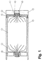
- the arrangement consists of a film tube (1), at least one closure element (2) and at least one flange (3), the flange (3) and film tube (1) being firmly connected to one another, for example by gluing.
- the flange (3) is designed to interact with the housing (9) of a device for emptying tubular bags.
- a piston (10) in the tubular bag (1) builds up a hydrostatic pressure which causes the substance (8) to flow out of the opening (13) on the outlet side of the tubular bag (1) .
- the flange (3) has the task of preventing the substance (8) from flowing into the interior of the container, device (12) (FIG. 1).
- the sealing effect is brought about by the fact that the arrangement according to the invention in the form of a collar seal (4) interacts with an opening (11) in the housing (9), which, for example, can be conically cylindrical or rounded.
- the sealing effect is supported by an elastic deformation of the collar seal (4) and a resulting prestress. If the substance now flows from the outlet side of the film tube (13) into the opening (11) of the housing (9), due to the pressures found in such devices, part of the substance will endeavor to flow back outside of the tubular bag or flange against the desired conveying direction . In this way, the substance will hit the inside (7) of the collar seal (4) where it will be stopped.
- the arrangement according to the invention also ensures an exact seal when the tubular bag and the flange (3) come in once when the bag is inserted a device should tilt at an angle ⁇ .
- the sealing effect is then due to the Collar seal (4) also enables because the collar seal (4) due to its elastic Properties in a non-rotationally metric form on the housing opening (11) can put on.
- the arrangement according to the invention works in that it is the substance it is possible to act on the entire inside of the sealing lip (7) (Figs. 3 and 4).
- the flange (3) has a slight circumference of the inside of the housing (9, 12) falling short (5).
- This design of the arrangement according to the invention makes a radially offset insertion of the tubular bag into an output device impossible.
Landscapes
- Engineering & Computer Science (AREA)
- Mechanical Engineering (AREA)
- Containers And Packaging Bodies Having A Special Means To Remove Contents (AREA)
- Devices For Use In Laboratory Experiments (AREA)
- Dental Tools And Instruments Or Auxiliary Dental Instruments (AREA)
Abstract
Description
Die Erfindung betrifft eine Anordnung zur Ausgabe fließfähiger Substanzen aus Folienschläuchen, wobei ein Abdichtelement in Form einer Kragendichtung die sichere und exakte Ausgabe der Substanz aus dem Folienbeutel sicherstellt.The invention relates to an arrangement for dispensing flowable substances from film tubes, a sealing element in the form of a collar seal the safe and ensures exact delivery of the substance from the foil bag.
Aus dem Stand der Technik ist das Ausbringen fließfähiger pastöser Massen, wie Dichtmassen oder zahnärztliche Abdruckmassen, aus einem Schlauchbeutel bekannt. Die dazu notwendigen Ausbringgeräte sind beispielsweise in der Druckschrift EP 0492413 beschrieben. Der Schlauchbeutel wird dazu in einen Zylinderraum eingebracht, der von einem Ende her mit einem Kolben beaufschlagt wird und am anderen Ende, an dem der Beutel geöffnet ist, eine Entleeröffnung oder Ausbringdüse aufweist. Die Druckschriften EP 0541972, EP 0663348, WO 98/06506 und WO 98/06505 beschreiben Möglichkeiten für das Auspressen fließfähiger Substanzen aus Schlauchbeuteln. Großes Augenmerk wird in diesen Druckschriften dabei immer auf die Abdichtvorrichtungen zwischen der Schlauchbeutelöffnung und der Entleeröffnung des Ausbringgerätes gelegt.The application of flowable pasty materials, such as sealing compounds, is known from the prior art or dental impression materials, known from a tubular bag. The Application devices required for this are described, for example, in the publication EP 0492413 described. For this purpose, the tubular bag is introduced into a cylinder space which is from one end is loaded with a piston and at the other end where the Bag is open, has an emptying opening or dispensing nozzle. The pamphlets EP 0541972, EP 0663348, WO 98/06506 and WO 98/06505 describe possibilities for squeezing flowable substances out of tubular bags. Great attention is always in these publications on the sealing devices between the Tubular bag opening and the discharge opening of the dispensing device.
In der Druckschrift EP 0541972 wird für die Abdichtung eine Anordnung gewählt, in dem ein Ring die Öffnungsseite des Folienschlauches umschließt, der wiederum eine konische Dichtfläche aufweist und mit einer ebenso konischen, die Ausbringöffnung des Gerätes umgebenden Gegenfläche zusammenwirkt. Die Druckschrift EP 0663348 beschreibt eine Abdichtvorrichtung, in dem der die Schlauchbeutelöffnung umgebende Ring einen den inneren Durchmesser des Gehäuses überschreitenden Randbereich aufweist, der zur Anlage an einer Stützfläche des Gehäuses geeignet ist. Nachteilig bei dieser Vorrichtung ist, daß die Schlauchbeutel nur in den Geräten verwendet werden können, die eine entsprechende Stützfläche am Gehäuse aufweisen.In the publication EP 0541972 an arrangement is selected for the seal in which a ring encloses the opening side of the film tube, which in turn is one has conical sealing surface and with an equally conical, the discharge opening of the Counter surface interacting device. EP 0663348 describes a sealing device in which the surrounding the tubular bag opening Ring an edge area exceeding the inner diameter of the housing has, which is suitable for bearing against a support surface of the housing. A disadvantage of this device is that the tubular bags are used only in the devices can have a corresponding support surface on the housing.
Die Druckschriften WO 98/06506 und WO 98/06505 beschreiben Anordnungen, in denen Dichtorgane, die als Dichtring an der Schlauchbeutelöffnung angebracht sind. Dieser Dichtring wirkt mit der die Entleeröffnung umgebenen Stirnflächen des Gerätes (WO 98/06505) oder mit der von dieser gebildeten Kante (WO 98/06506) zusammen. Es handelt sich bei diesen Dichtorganen um Dichtscheiben, O-ringe oder Ringe aus Schaumgummi mit geschlossener Oberfläche an denen zusätzlich Saughalter befestigt sein können. The publications WO 98/06506 and WO 98/06505 describe arrangements in those sealing elements that are attached to the tubular bag opening as a sealing ring. This sealing ring acts with the end faces of the device surrounding the drain opening (WO 98/06505) or together with the edge formed by this (WO 98/06506). It these sealing elements are made of sealing washers, O-rings or rings Foam rubber with a closed surface to which suction cups are additionally attached could be.
Nachteilig bei den in den o.g. Druckschriften beschriebenen Anordnungen zum Auspressen fließfähiger Substanzen ist, daß eine sichere Abdichtwirkung der Dichtorgane während der gesamten Ausbringung der fließfähigen Substanz nicht gewährleistet ist. Vor allem dann wenn der Ausbringvorgang unterbrochen wird und zu einem späteren Zeitpunkt erneut Substanz ausgebracht werden soll.A disadvantage of the in the above Printed arrangements described for pressing flowable substances is that a reliable sealing effect of the sealing elements is not guaranteed during the entire application of the flowable substance. Especially when the application process is interrupted and at a later time Substance should be applied again at the time.
Es ist bekannt, daß handelsübliche Schlauchbeutel mit Flanschen und den Abdichtorganen, wie in den o.g. Druckschriften beschrieben, dazu neigen "zu atmen", wenn die Belastung durch einen Ausbringkolben zurückgenommen wird, d.h. der Ausdrückvorgang angehalten wird. In diesem Fall wird die Abdichtanordnung um eine geringe Strecke zurückgedrückt und die Substanz kann in den dabei entstehenden Zwischenraum zwischen Abdichtung und umgebendes Gehäuse eindringen. Bei den dargestellten Anordnungen bzw. Vorrichtungen entsteht durch dieses "atmen" ein Spalt zwischen Flansch und Gehäuseinnenseite. Bei der Anordnung gemäß WO 98/06505 bzw. WO 98/06506 wird der Spalt zwischen dem Dichtorgan, das an der Stirnseite des Flansches angebracht ist, und der die Entlereröffnung umgebende Stirnfläche des Gehäuses bei jeder Rückbewegung des Entleerdruckes auf den Folienbeutel um das gleiche Maß zunehmen. Es gibt bei diesen Ausführungsformen einen direkten Zusammenhang zwischen dem "atmen" (Rückbewegung des Beutels) und der Vergrößerung des Spaltes, durch den die auszudrückende Substanz in das Gehäuse dringen kann. Bei der Anordnung gemäß EP 663348 wird dieser direkte geometrische Zusammenhang verringert, jedoch nicht abgestellt. Aufgrund des Zusammenwirken zweier konischer Dichtflächen entsteht, abhängig vom Kegelwinkel des Konus, eine Art "Untersetzung", d.h. jedes Maß an Weglänge des Flansches beim "atmen" führt zu einem entsprechenden kleineren Maß der Spaltvergrößerung. Eine Verhinderung der Spaltbildung wird aber nicht realisiert. Eine sichere Abdichtung mit den bekannten Anordnungen ist somit nicht gewährleistet, insbesondere dann nicht, wenn der Schlauchbeutel sich einmal bei dem Einsetzen in ein Ausgabegerät verkannten sollte.It is known that commercially available tubular bags with flanges and the sealing elements, as in the above Publications described tend to "breathe" when the Load is reduced by a discharge piston, i.e. the squeezing process is stopped. In this case, the sealing arrangement becomes small Stretched back and the substance can in the resulting space penetrate between the seal and the surrounding housing. In the illustrated Arrangements or devices result from this "breathing" a gap between Flange and inside of housing. In the arrangement according to WO 98/06505 or WO 98/06506 is the gap between the sealing member, which is on the face of the flange is attached, and the end face of the housing surrounding the emitter opening increase each return movement of the discharge pressure on the foil bag by the same amount. There is a direct relationship in these embodiments between "breathing" (backward movement of the bag) and the widening of the gap, through which the substance to be expressed can penetrate into the housing. In the arrangement according to EP 663348, this direct geometric connection becomes reduced but not turned off. Because of the interaction of two conical Depending on the cone angle of the cone, sealing surfaces form a kind of "reduction", i.e. every degree of path length of the flange when "breathing" leads to a corresponding one smaller amount of gap enlargement. Prevention of the gap formation will unrealized. A secure seal with the known arrangements is therefore not guaranteed, especially not if the tubular bag is at the Inserting into an output device should not be recognized.
Darüber hinaus ist eine Anordnung zur Abdichtung erstrebenswert, die geringe Materialkosten aufweist und aufwendige und unpraktikable Befestigungsmöglichkeiten vermeidet. Des weiteren sollte die Abdichtanordnung das einfache Entnehmen des Folienschlauches aus einem Gerät gewährleisten sowie eine einfache und schnelle Reinigung der gesamten Anordnung sicherstellen. In addition, an arrangement for sealing is desirable, the low material costs has and avoids complex and impractical mounting options. Furthermore, the sealing arrangement should be the simple removal of the film tube guarantee from one device as well as simple and quick cleaning ensure the entire arrangement.
Aufgabe der Erfindung ist es daher, eine Anordnung zur Ausgabe fließfähiger Substanzen aus Folienschläuchen anzugeben, welche die o.g. Nachteile vermeidet. Insbesondere ist es die Aufgabe der vorliegenden Erfindung eine Anordnung bereit zu stellen, die selbst beim verkanteten Einsetzen eines Schlauchbeutels in ein Ausgabegerät, eine vollständige Abdichtung bei der Ausgabe der fließfähigen Substanz aus dem Folienbeutel ermöglicht.The object of the invention is therefore an arrangement for dispensing flowable substances from film tubes, which specify the above Avoids disadvantages. In particular it is the object of the present invention to provide an arrangement which even when inserting a tubular bag into an output device, a complete sealing when dispensing the flowable substance from the foil bag enables.
Die Aufgabe wird durch die Anordnung gemäß Hauptanspruch 1 gelöst. Die erfindungsgemäße
Anordnung beinhaltet ein Abdichtelement in Form einer Kragendichtung, das
die sichere und exakte Abgabe der auszugebenden Substanz sicherstellt. Die erfindungsgemäße
Abdichtanordnung wirkt dabei nicht mit der die Ausbringöffnung des
Ausgabegerätes umgebende Stirnfläche zusammen, sondern mit der Ausbringöffnung
direkt. Die Erfindung wird im folgenden unter näherem Bezug auf die Abbildungen 1, 2, 3
und 4, die vorteilhafte Ausführungsbeispiele darstellen, erläutert.The object is achieved by the arrangement according to
Die Anordnung besteht aus einem Folienschlauch (1), mindestens einem Verschlußelement
(2) und mindestens einem Flansch (3), wobei Flansch (3) und Folienschlauch (1)
fest miteinander verbunden sind, beispielsweise durch Verklebung. Der Flansch (3) ist
dazu ausgelegt, mit dem Gehäuse (9) eines Gerätes zur Entleerung von Schlauchbeuteln
zusammenzuwirken. Bei der Entleerung des Schlauchbeutels (1) wird durch
einen Kolben (10) im Schlauchbeutel (1) ein hydrostatischer Druck aufgebaut, der dazu
führt, daß die Substanz (8) aus der Öffnung (13) an der Austrittsseite des Schlauchbeutels
(1) fließt. Der Flansch (3) hat die Aufgabe, die Substanz (8) darin zu hindern in
den Innenraum des Behälters, Gerätes (12) zu fließen (Fig. 1).
Die Dichtwirkung wird dadurch bewirkt, daß die erfindungsgemäße Anordnung in Form
einer Kragendichtung (4) mit einer Öffnung (11) des Gehäuses (9), die beispielsweise
konisch zylindrisch oder abgerundet ausgeführt sein kann, zusammenwirkt. Bei einer
konisch ausgeführten Öffnung (11), wie sie in handelsüblichen Geräten vorzufinden ist,
wird die Dichtwirkung unterstützt durch eine elastische Verformung der Kragendichtung
(4) und eine daraus resultierende Vorspannung. Fließt nun die Substanz aus der Austrittseite
des Folienschlauches (13) in die Öffnung (11) des Gehäuses (9) so wird aufgrund
der in solchen Geräten vorzufindenden Drucke ein Teil der Substanz bestrebt
sein, entgegen der gewollten Förderrichtung außen am Schlauchbeutel bzw. Flansch
zurückzufließen. Auf diesem Weg wird die Substanz auf die Innenseite (7) der Kragendichtung
(4) treffen, wo sie aufgehalten wird. Steigt nun der hydrostatische Druck an der
Innenseite (7) an, so entsteht eine zusätzlich zur Vorspannung wirkende Anpresskraft
zwischen der Anlegelinie der Kragendichtung (6) und der Öffnung (11) des Gehäuses,
die die Dichtwirkung um so mehr steigert je höher der hydrostatische Druck an der
Innenseite (7) der Kragendichtung (4) ansteigt (Fig. 1 und 2).The arrangement consists of a film tube (1), at least one closure element (2) and at least one flange (3), the flange (3) and film tube (1) being firmly connected to one another, for example by gluing. The flange (3) is designed to interact with the housing (9) of a device for emptying tubular bags. When the tubular bag (1) is emptied, a piston (10) in the tubular bag (1) builds up a hydrostatic pressure which causes the substance (8) to flow out of the opening (13) on the outlet side of the tubular bag (1) . The flange (3) has the task of preventing the substance (8) from flowing into the interior of the container, device (12) (FIG. 1).
The sealing effect is brought about by the fact that the arrangement according to the invention in the form of a collar seal (4) interacts with an opening (11) in the housing (9), which, for example, can be conically cylindrical or rounded. In the case of a conical opening (11), as can be found in commercially available devices, the sealing effect is supported by an elastic deformation of the collar seal (4) and a resulting prestress. If the substance now flows from the outlet side of the film tube (13) into the opening (11) of the housing (9), due to the pressures found in such devices, part of the substance will endeavor to flow back outside of the tubular bag or flange against the desired conveying direction . In this way, the substance will hit the inside (7) of the collar seal (4) where it will be stopped. If the hydrostatic pressure on the inside (7) now rises, a contact force that acts in addition to the prestressing arises between the contact line of the collar seal (6) and the opening (11) of the housing, which increases the sealing effect the higher the hydrostatic pressure on the inside (7) of the collar seal (4) rises (Fig. 1 and 2).
Es hat sich gezeigt, daß handelsübliche Schlauchbeutel mit Flansch und den Abdichtorganen,
wie in den Druckschriften zum Stand der Technik beschrieben, dazu neigen "zu
atmen", wenn die Belastung durch einen Kolben zurückgenommen wird, d.h. der Ausdrückvorgang
angehalten wird. In diesen Anordnungen wird der Flansch um eine geringe
Strecke zurückgedrückt und die Substanz kann in den dabei entstehenden Zwischenraum
zwischen Flansch und Gehäuse eindringen. Bei der erfindungsgemäßen Anordnung
wird dieser Nachteil dadurch wirksam unterbunden, daß bedingt durch die Vorspannung
und der damit verbundenen elastischen Verformung der Kragendichtung (4)
bei dem "Atmen" kein Spalt zwischen dem Dichtorgan (hier Kragendichtung (4)) und dem
Gehäuse entstehen kann.
Bei neuerlichem Einsetzen der Kolbenkraft wird der Flansch (3) bedingt durch sein im
Verhältnis zur Austrittsöffnung großen Durchmesser in Förderrichtung geschoben. Der
Teil der Substanz, der beim Atmen den Flansch (4) zurückgeschoben hat, wird dann
durch die Innenseite der Kragendichtung (7) sauber von der Wandung der Gehäuseöffnung
(11) abgestriffen, was bei keiner der bekannten Anordnungen möglich ist.It has been found that commercially available tubular bags with a flange and the sealing elements, as described in the prior art documents, tend to "breathe" when the load is reduced by a piston, ie the squeezing process is stopped. In these arrangements, the flange is pushed back a short distance and the substance can penetrate into the resulting space between the flange and the housing. In the arrangement according to the invention, this disadvantage is effectively prevented by the fact that due to the pretension and the associated elastic deformation of the collar seal (4), no gap can arise between the sealing member (here collar seal (4)) and the housing during "breathing".
When the piston force is used again, the flange (3) is pushed in the conveying direction due to its large diameter in relation to the outlet opening. The part of the substance that has pushed the flange (4) back during breathing is then wiped cleanly from the wall of the housing opening (11) through the inside of the collar seal (7), which is not possible with any of the known arrangements.
Die erfindungsgemäße Anordnung stellt auch dann eine exakte Abdichtung sicher, wenn der Schlauchbeutel und der Flansch (3) sich einmal bei dem Einsetzen des Beutels in ein Gerät um einen Winkel γ verkanten sollte. Die Dichtwirkung wird dann aufgrund der Kragendichtung (4) ebenfalls ermöglicht, da die Kragendichtung (4) aufgrund ihrer elastischen Eigenschaften sich in nicht rotationsmetrischer Form an die Gehäuseöffnung (11) anlegen kann. Die erfindungsgemäße Anordnung funktioniert dadurch, daß es der Substanz möglich ist, im gesamten Umfang auf die Innenseite (7) der Dichtlippe zu wirken (Fig. 3 und 4).The arrangement according to the invention also ensures an exact seal when the tubular bag and the flange (3) come in once when the bag is inserted a device should tilt at an angle γ. The sealing effect is then due to the Collar seal (4) also enables because the collar seal (4) due to its elastic Properties in a non-rotationally metric form on the housing opening (11) can put on. The arrangement according to the invention works in that it is the substance it is possible to act on the entire inside of the sealing lip (7) (Figs. 3 and 4).
Um das Einsetzen des kompletten Schlauchbeutels (1) in ein Ausgabegerät zu erleichtern, besitzt der Flansch (3) einen den Umfang der Innenseite des Gehäuses (9, 12) geringfügig unterschreitenden Umfang (5). Diese Bauform der erfindungsgemäßen Anordnung macht ein radial versetztes Einsetzen des Schlauchbeutels in ein Ausgabegerät unmöglich. To make it easier to insert the entire tubular bag (1) into an output device, the flange (3) has a slight circumference of the inside of the housing (9, 12) falling short (5). This design of the arrangement according to the invention makes a radially offset insertion of the tubular bag into an output device impossible.
Die Vorteile der oben beschriebenen erfindungsgemäßen Anordnung ergeben sich damit zu:
- hohe Dichtwirkung trotz Verkanten
- unproblematische Anwendung auch bei Verschmutzung
- hohe Anpresskraft und hohe Dichtkraft
- bei Beendigung der Kolbenkraft wird die Dichtanordnung zurückgedrückt und kann sich entlasten. Bei erneutem Einsetzen der Kolbenkraft wird evtl. zurückgedrücktes Material wieder nach vorn ausgegeben.
- selbstwirkende Dichtung
- Abdichtungfunktion ist auch bei zylindrischer Bohrung, z.B. mit Radiusansatz gewährleistet.
- high sealing effect despite tilting
- unproblematic use even when dirty
- high contact pressure and high sealing force
- at the end of the piston force, the sealing arrangement is pushed back and can relieve itself. When the piston force is reapplied, any material that has been pushed back is released to the front.
- self-acting seal
- Sealing function is also guaranteed with a cylindrical bore, eg with a radius attachment.
Legende der in den Abbbildungen 1 bis 4 dargestellten Anordnungsbauteilen:
Claims (5)
Applications Claiming Priority (2)
| Application Number | Priority Date | Filing Date | Title |
|---|---|---|---|
| DE29813684U DE29813684U1 (en) | 1998-07-31 | 1998-07-31 | Arrangement for dispensing flowable substances from film tubes |
| DE29813684U | 1998-07-31 |
Publications (2)
| Publication Number | Publication Date |
|---|---|
| EP0976458A2 true EP0976458A2 (en) | 2000-02-02 |
| EP0976458A3 EP0976458A3 (en) | 2002-05-29 |
Family
ID=8060659
Family Applications (1)
| Application Number | Title | Priority Date | Filing Date |
|---|---|---|---|
| EP99114912A Withdrawn EP0976458A3 (en) | 1998-07-31 | 1999-07-30 | Device for discharging flowable materials from flexible tubular bags |
Country Status (2)
| Country | Link |
|---|---|
| EP (1) | EP0976458A3 (en) |
| DE (2) | DE29813684U1 (en) |
Cited By (1)
| Publication number | Priority date | Publication date | Assignee | Title |
|---|---|---|---|---|
| EP1524204A1 (en) | 2003-10-15 | 2005-04-20 | HILTI Aktiengesellschaft | Head piece for multi-compartment tubular bag |
Families Citing this family (1)
| Publication number | Priority date | Publication date | Assignee | Title |
|---|---|---|---|---|
| GB2437596A (en) * | 2006-04-25 | 2007-10-31 | Exchem Plc | Dispenser cartridge |
Citations (4)
| Publication number | Priority date | Publication date | Assignee | Title |
|---|---|---|---|---|
| EP0492413A1 (en) | 1990-12-21 | 1992-07-01 | THERA Patent GmbH & Co. KG Gesellschaft für industrielle Schutzrechte | Device for mixing and applying masses composed of several components |
| EP0541972A1 (en) | 1991-11-12 | 1993-05-19 | THERA Patent GmbH & Co. KG Gesellschaft für industrielle Schutzrechte | Container for flowable products |
| EP0663348A1 (en) | 1994-01-13 | 1995-07-19 | THERA Patent GmbH & Co. KG Gesellschaft für industrielle Schutzrechte | Device for emptying a tubular bag |
| WO1998006506A1 (en) | 1996-08-12 | 1998-02-19 | Muehlbauer Ernst | Device for squeezing flowable material out of a tubular bag |
Family Cites Families (1)
| Publication number | Priority date | Publication date | Assignee | Title |
|---|---|---|---|---|
| EP0855349B1 (en) * | 1996-12-24 | 2005-07-27 | Mixpac Systems AG | Cartridge assembly for the use of an invertible package |
-
1998
- 1998-07-31 DE DE29813684U patent/DE29813684U1/en not_active Expired - Lifetime
-
1999
- 1999-07-30 DE DE19936045A patent/DE19936045A1/en not_active Withdrawn
- 1999-07-30 EP EP99114912A patent/EP0976458A3/en not_active Withdrawn
Patent Citations (5)
| Publication number | Priority date | Publication date | Assignee | Title |
|---|---|---|---|---|
| EP0492413A1 (en) | 1990-12-21 | 1992-07-01 | THERA Patent GmbH & Co. KG Gesellschaft für industrielle Schutzrechte | Device for mixing and applying masses composed of several components |
| EP0541972A1 (en) | 1991-11-12 | 1993-05-19 | THERA Patent GmbH & Co. KG Gesellschaft für industrielle Schutzrechte | Container for flowable products |
| EP0663348A1 (en) | 1994-01-13 | 1995-07-19 | THERA Patent GmbH & Co. KG Gesellschaft für industrielle Schutzrechte | Device for emptying a tubular bag |
| WO1998006506A1 (en) | 1996-08-12 | 1998-02-19 | Muehlbauer Ernst | Device for squeezing flowable material out of a tubular bag |
| WO1998006505A1 (en) | 1996-08-12 | 1998-02-19 | Muehlbauer Ernst | Device for squeezing flowable material out of a tubular bag |
Cited By (3)
| Publication number | Priority date | Publication date | Assignee | Title |
|---|---|---|---|---|
| EP1524204A1 (en) | 2003-10-15 | 2005-04-20 | HILTI Aktiengesellschaft | Head piece for multi-compartment tubular bag |
| JP2005119749A (en) * | 2003-10-15 | 2005-05-12 | Hilti Ag | Extrusion head for multi-chamber hose bags |
| CN100522755C (en) * | 2003-10-15 | 2009-08-05 | 希尔蒂股份公司 | Head piece for multi-compartment tubular bag |
Also Published As
| Publication number | Publication date |
|---|---|
| DE29813684U1 (en) | 1998-12-17 |
| EP0976458A3 (en) | 2002-05-29 |
| DE19936045A1 (en) | 2000-01-27 |
Similar Documents
| Publication | Publication Date | Title |
|---|---|---|
| EP0663348B1 (en) | Device for emptying a tubular bag | |
| EP0519292B1 (en) | Siringe-like device for dosing fluids or pastes | |
| AT512679B1 (en) | Device for mixing | |
| EP0579889B1 (en) | Mixer and attachment | |
| DE10300494A1 (en) | Pump for dispensing flowable material | |
| DE3210668A1 (en) | SHUT-OFF ORGAN | |
| EP0254969A1 (en) | Apparatus for extruding pastes | |
| EP2134475A1 (en) | Device for spraying pigmented fluids | |
| DE2717878A1 (en) | DEVICE FOR DOSED DISPENSING OF LIQUIDS OR PASTS | |
| DE4212434A1 (en) | Arrangement for refilling a container | |
| DE102007041035B4 (en) | Valve body, valve, pumping device and apparatus for producing valve bodies | |
| EP0394383A1 (en) | Hose pump. | |
| CH684082A5 (en) | Container. | |
| DE102010047747A1 (en) | One-way valve, particularly for medicinal usage such as for infusion set, has valve housing, inlet opening, outlet opening and valve arrangement, which consists of valve body and valve seal | |
| DE69204317T2 (en) | Device for dispensing liquid detergents and / or detergents in a washing machine. | |
| WO2010118764A1 (en) | Liquid pump appliance | |
| EP0976458A2 (en) | Device for discharging flowable materials from flexible tubular bags | |
| DE9419268U1 (en) | donor | |
| DE19518034A1 (en) | Filling device for the metered delivery of highly viscous materials | |
| EP0059928A1 (en) | Means for emptying a cylindrical container containing, in particular, a viscous product | |
| DE69903435T2 (en) | DISPENSER FOR DISPENSING A VISCOSE SUBSTANCE, e.g. AN ANTISEPTIC LIQUID, AND CONTAINER FOR SUCH DISPENSER | |
| EP3444210A1 (en) | Connecting device for connecting a flexible first container to a dimensionally stable second container | |
| DE102011005816B4 (en) | metering | |
| DE2026922C2 (en) | Plastic canisters | |
| EP2419162B1 (en) | Liquid pump appliance |
Legal Events
| Date | Code | Title | Description |
|---|---|---|---|
| PUAI | Public reference made under article 153(3) epc to a published international application that has entered the european phase |
Free format text: ORIGINAL CODE: 0009012 |
|
| AK | Designated contracting states |
Kind code of ref document: A2 Designated state(s): AT BE CH CY DE DK ES FI FR GB GR IE IT LI LU MC NL PT SE |
|
| AX | Request for extension of the european patent |
Free format text: AL;LT;LV;MK;RO;SI |
|
| PUAL | Search report despatched |
Free format text: ORIGINAL CODE: 0009013 |
|
| AK | Designated contracting states |
Kind code of ref document: A3 Designated state(s): AT BE CH CY DE DK ES FI FR GB GR IE IT LI LU MC NL PT SE |
|
| AX | Request for extension of the european patent |
Free format text: AL;LT;LV;MK;RO;SI |
|
| RIC1 | Information provided on ipc code assigned before grant |
Free format text: 7B 05C 17/01 A, 7B 65D 83/00 B, 7B 05C 17/005 B |
|
| AKX | Designation fees paid | ||
| REG | Reference to a national code |
Ref country code: DE Ref legal event code: 8566 |
|
| STAA | Information on the status of an ep patent application or granted ep patent |
Free format text: STATUS: THE APPLICATION IS DEEMED TO BE WITHDRAWN |
|
| 18D | Application deemed to be withdrawn |
Effective date: 20021130 |