EP0976481A2 - Cylindre à serrer rapide sans couverture - Google Patents
Cylindre à serrer rapide sans couverture Download PDFInfo
- Publication number
- EP0976481A2 EP0976481A2 EP99114661A EP99114661A EP0976481A2 EP 0976481 A2 EP0976481 A2 EP 0976481A2 EP 99114661 A EP99114661 A EP 99114661A EP 99114661 A EP99114661 A EP 99114661A EP 0976481 A2 EP0976481 A2 EP 0976481A2
- Authority
- EP
- European Patent Office
- Prior art keywords
- quick
- clamping cylinder
- housing
- action clamping
- cylinder
- Prior art date
- Legal status (The legal status is an assumption and is not a legal conclusion. Google has not performed a legal analysis and makes no representation as to the accuracy of the status listed.)
- Granted
Links
- 210000002445 nipple Anatomy 0.000 claims abstract description 45
- 239000003921 oil Substances 0.000 claims description 25
- 238000000034 method Methods 0.000 claims description 16
- 238000007789 sealing Methods 0.000 claims description 10
- 238000012545 processing Methods 0.000 claims description 8
- 238000009434 installation Methods 0.000 claims description 5
- 238000003754 machining Methods 0.000 claims description 5
- 238000003825 pressing Methods 0.000 claims description 5
- 238000007664 blowing Methods 0.000 claims description 4
- 239000010720 hydraulic oil Substances 0.000 claims description 3
- 230000035515 penetration Effects 0.000 claims description 3
- 238000013459 approach Methods 0.000 description 8
- 238000004519 manufacturing process Methods 0.000 description 5
- 230000000694 effects Effects 0.000 description 4
- 210000000078 claw Anatomy 0.000 description 3
- 238000004140 cleaning Methods 0.000 description 3
- 239000002826 coolant Substances 0.000 description 3
- 238000013461 design Methods 0.000 description 3
- 238000006073 displacement reaction Methods 0.000 description 3
- 238000005553 drilling Methods 0.000 description 3
- 125000006850 spacer group Chemical group 0.000 description 3
- 238000005452 bending Methods 0.000 description 2
- 238000010276 construction Methods 0.000 description 2
- 239000000463 material Substances 0.000 description 2
- XLYOFNOQVPJJNP-UHFFFAOYSA-N water Substances O XLYOFNOQVPJJNP-UHFFFAOYSA-N 0.000 description 2
- 206010038944 Retracted nipple Diseases 0.000 description 1
- 230000002411 adverse Effects 0.000 description 1
- 230000000712 assembly Effects 0.000 description 1
- 238000000429 assembly Methods 0.000 description 1
- 230000015572 biosynthetic process Effects 0.000 description 1
- 238000011109 contamination Methods 0.000 description 1
- 230000001186 cumulative effect Effects 0.000 description 1
- 238000011161 development Methods 0.000 description 1
- 239000004744 fabric Substances 0.000 description 1
- 210000003746 feather Anatomy 0.000 description 1
- 238000007654 immersion Methods 0.000 description 1
- 239000002655 kraft paper Substances 0.000 description 1
- 239000002184 metal Substances 0.000 description 1
- 238000003801 milling Methods 0.000 description 1
- 230000002093 peripheral effect Effects 0.000 description 1
- 210000003813 thumb Anatomy 0.000 description 1
- 238000012549 training Methods 0.000 description 1
- 238000012546 transfer Methods 0.000 description 1
- 230000003313 weakening effect Effects 0.000 description 1
Images


Classifications
-
- B—PERFORMING OPERATIONS; TRANSPORTING
- B23—MACHINE TOOLS; METAL-WORKING NOT OTHERWISE PROVIDED FOR
- B23B—TURNING; BORING
- B23B31/00—Chucks; Expansion mandrels; Adaptations thereof for remote control
- B23B31/02—Chucks
- B23B31/24—Chucks characterised by features relating primarily to remote control of the gripping means
- B23B31/30—Chucks characterised by features relating primarily to remote control of the gripping means using fluid-pressure means in the chuck
-
- B—PERFORMING OPERATIONS; TRANSPORTING
- B23—MACHINE TOOLS; METAL-WORKING NOT OTHERWISE PROVIDED FOR
- B23B—TURNING; BORING
- B23B31/00—Chucks; Expansion mandrels; Adaptations thereof for remote control
- B23B31/02—Chucks
- B23B31/10—Chucks characterised by the retaining or gripping devices or their immediate operating means
- B23B31/107—Retention by laterally-acting detents, e.g. pins, screws, wedges; Retention by loose elements, e.g. balls
- B23B31/1071—Retention by balls
-
- B—PERFORMING OPERATIONS; TRANSPORTING
- B23—MACHINE TOOLS; METAL-WORKING NOT OTHERWISE PROVIDED FOR
- B23B—TURNING; BORING
- B23B31/00—Chucks; Expansion mandrels; Adaptations thereof for remote control
- B23B31/02—Chucks
- B23B31/10—Chucks characterised by the retaining or gripping devices or their immediate operating means
- B23B31/12—Chucks with simultaneously-acting jaws, whether or not also individually adjustable
- B23B31/22—Jaws in the form of balls
-
- B—PERFORMING OPERATIONS; TRANSPORTING
- B23—MACHINE TOOLS; METAL-WORKING NOT OTHERWISE PROVIDED FOR
- B23B—TURNING; BORING
- B23B31/00—Chucks; Expansion mandrels; Adaptations thereof for remote control
- B23B31/02—Chucks
- B23B31/24—Chucks characterised by features relating primarily to remote control of the gripping means
- B23B31/30—Chucks characterised by features relating primarily to remote control of the gripping means using fluid-pressure means in the chuck
- B23B31/302—Hydraulic equipment, e.g. pistons, valves, rotary joints
-
- B—PERFORMING OPERATIONS; TRANSPORTING
- B23—MACHINE TOOLS; METAL-WORKING NOT OTHERWISE PROVIDED FOR
- B23P—METAL-WORKING NOT OTHERWISE PROVIDED FOR; COMBINED OPERATIONS; UNIVERSAL MACHINE TOOLS
- B23P19/00—Machines for simply fitting together or separating metal parts or objects, or metal and non-metal parts, whether or not involving some deformation; Tools or devices therefor so far as not provided for in other classes
- B23P19/04—Machines for simply fitting together or separating metal parts or objects, or metal and non-metal parts, whether or not involving some deformation; Tools or devices therefor so far as not provided for in other classes for assembling or disassembling parts
-
- B—PERFORMING OPERATIONS; TRANSPORTING
- B23—MACHINE TOOLS; METAL-WORKING NOT OTHERWISE PROVIDED FOR
- B23Q—DETAILS, COMPONENTS, OR ACCESSORIES FOR MACHINE TOOLS, e.g. ARRANGEMENTS FOR COPYING OR CONTROLLING; MACHINE TOOLS IN GENERAL CHARACTERISED BY THE CONSTRUCTION OF PARTICULAR DETAILS OR COMPONENTS; COMBINATIONS OR ASSOCIATIONS OF METAL-WORKING MACHINES, NOT DIRECTED TO A PARTICULAR RESULT
- B23Q1/00—Members which are comprised in the general build-up of a form of machine, particularly relatively large fixed members
- B23Q1/0063—Connecting non-slidable parts of machine tools to each other
- B23Q1/0072—Connecting non-slidable parts of machine tools to each other using a clamping opening for receiving an insertion bolt or nipple
Definitions
- the present invention relates to a method for manufacturing and assembly as well a lidless quick release cylinder manufactured by this method Retractable nipple for clamping a carrier plate, also called a pallet, on one Processing machine for fixing workpieces.
- Quick release cylinders are for Clamping devices for clamping workpieces on carrier plates for Processing machines needed.
- a quick release cylinder is for example with DE-GM 296 15, which goes back to the same applicant 613 became known.
- Such a quick release cylinder is characterized by that the receptacles for holding the Tension springs are incorporated and that the housing by an associated Lid is completed from above.
- the lid has a central recess, in which is hydraulically sealed and flush with the retractable nipple is displaceable.
- the production of the cover requires complex processing steps, because the cover must be processed as a single part with high precision; he needs appropriate ones circumferential through holes arranged around the circumference. Further he needs a highly precise machining on the outer circumference and on one assigned shoulder so that it fits excessively, precisely, in the open top Recess of the housing can be pressed. So it will be a press fit used with a correspondingly highly precise machining of the top open housing and the associated lid is connected.
- the lid is seated on the Housing of the quick release cylinder formed, i.e. the quick release cylinder forms an upward elongated approach from the front of the lid is placed and screwed with appropriate threaded holes.
- the pull-in force of the pull-in nipple passing through the cover is so can be large that the lid is deformed.
- the total height of the quick release cylinder (the height of the housing of the Cylinder and the cover) is precisely defined, can also be a cumulative error arise when the two heights do not match.
- the lid in a assigned, upwardly open recess of the housing is used, wherein this recess has a circumferential edge, the edge slightly protrudes from the surface of the lid. So the lid - like in that Shown previously mentioned utility model - embraced by the peripheral edge and appropriately recorded.
- the assembly of such a quick release cylinder is relative expensive, because first with the cover removed in the upwardly open recess the springs of the housing of the quick release cylinder.
- the Springs are mounted so that they are first in the relaxed state in the Housing of the quick release cylinder can be used. Then the lid put on and under the influence of a press that acts on the top of the lid, this against the force of the springs inwards into the housing of the Quick release cylinder pressed into it. Then with the on the lid circumferentially arranged mounting screws of the cover with the housing of the Bolted quick release cylinder.
- connection of the lid with the housing of the quick release cylinder is only under pressure, which can result can that certain parts of the Quick release cylinders can be damaged. Furthermore, they have to fit perfectly under Action of the pressing force the through holes in the cover with the associated Tapped holes in the housing of the quick release cylinder in accordance be brought to enable assembly of the lid at all.
- the mounting screws used to connect the cover to the housing the quick release cylinder have the further disadvantage that this makes valuable Area on the surface of the lid is lost, e.g. for the arrangement of Blow-out grooves or blow-out holes could be used. This Blow holes must then be outside of the corresponding Fastening holes are made in the lid, which results in an increased Manufacturing effort, and moreover with a weakening of the material thickness of the Lid is connected.
- the invention is therefore based on the object of a method for assembling a To develop quick release cylinder, and a manufactured according to the process To design quick release cylinders so that a much simpler, less expensive, more resilient and reliable construction of the Quick release cylinder is guaranteed.
- the invention is by the method according to Claim 1 marked.
- An essential feature of the invention is that now a top cover of the The quick release cylinder is completely eliminated because the top of the cylinder housing at the same time forms the lid. A corresponding top cover is therefore not required Completely. Instead, an underside is used, the has significant advantages over the prior art.
- a floor must namely not manufactured at all precisely because there are no clamping forces on it Act. He only has to take up the oil pressure because he has the bottom limit of the cylinder housing and is loaded with oil pressure on its surface. It exists Accordingly, there is no longer any risk that this cover due to impermissibly high clamping forces is bent.
- blowout holes can be in a blow-out ring can be arranged, which sinks in a circumferential groove is appropriate.
- the blow-out holes are over a circumference in the Blow-out ring arranged so that a uniform application of compressed air can take place along the circumference of the ring.
- this loading causes blowing out drilling chips and coolant, and secondly the very important one Aspect as a safety precaution for targeted pressure reduction of the appropriate holes also attacking on the underside of the retractable nipple Compressed air.
- the second air stream is directed upwards from the branch to the blow ring.
- This partial flow of compressed air is also used to blow out the Quick clamping cylinder used after machining the workpiece.
- the Blow out takes place here on the top of the quick release cylinder and is for cleaning of the contact surface for the range of drilling chips and coolants thought. Reduced by this branched partial flow of the compressed air supplied the effective air pressure in the line system of the quick release cylinder, and thus also on the effective contact surface on the underside of the retractable nipple.
- this danger no longer exists because it is corresponding Large and stable stops can be provided in the cylinder housing, the one Damage to the cylinder housing in the ceiling area, as previously described avoid.
- the new quick release cylinder is structurally characterized by the following essential features from:
- the cylinder housing is self-contained on the ceiling and only forms one central, central recess for the penetration of the retractable nipple. It is integrally connected to the side surfaces, so that there is a U-shaped profile Body results that is open at the bottom and that in its interior Cylinder space for receiving the piston forms.
- this floor which prevents that the bottom is moved outwards from the cylinder housing.
- this floor is arranged in a stationary and sealed manner in the cylinder housing and forms the lower limit of the oil space.
- the piston opposite contact surface for the springs of the clamping cylinder from one resilient stop which is preferably made of one piece with the Cylinder housing is formed.
- This stop thus forms the bearing for the Spring, thus the spring pressure from the upper limit of the Cylinder housing is kept away.
- Stop in the form of a circlip can be used.
- FIG. 1 In general, it should be noted for the illustration in FIG. 1 that it consists of two partial sections there, the left half cut the quick release cylinder 1 in tensioned Condition shows, while the right half cut the quick release cylinder 1 in the released Condition shows.
- the right half shows a circlip 24, which alternatively to the groove 26 on the left half is.
- the quick release cylinder can therefore either realized with the Seegerring 24 or only with the recess 26 become.
- FIG. 1 thus shows a preferred embodiment of a Quick release cylinder 1. It consists essentially of a housing 2, which - essential for the present invention - in its upper part in itself is closed and accordingly forms a closed ceiling area that is integrally formed with the housing 2. This area goes accordingly in the side flanks, so that this housing 2 forms a round part, the under other forms the oil space 12.
- One or more lugs 3 are formed on the housing, the lugs can have different profile shapes.
- Such an approach 3 can be used as Square, as a polygon, or as a non-circular approach. It serves one above and not shown clamping pallet to carry and secure against rotation.
- the clamping pallet in turn forms a central recess in which the Retractable nipple 17 protrudes.
- the retractable nipple 17 is - in not shown Way - connected to a clamping element, the clamping element then with the tool to be clamped interacts.
- the quick release cylinder 1 is assigned by means of a stop claw 33 and Screws 34 on a perforated grid pallet, not shown in more detail spanned.
- a clamping on a T-slot table is also provided.
- the O-ring 5 prevents splashing or immersion water from the outside in the direction of the retractable nipple 17 and the recess occupied by the retractable nipple in Housing 2 penetrates.
- the O-ring 5 thus seals with (not shown in the drawing) Clamping range.
- An air inlet 30 is provided for supplying air to the blow holes 7. which opens into the blow hole 7 via a cross hole 31 and a channel 32.
- This cross hole 31 is used to distribute the compressed air supplied, on the one hand to ensure the function of blowing, and on the other hand a targeted Pressure drop in the compressed air at the effective surface at the bottom of the To reach the retractable nipple (17). This measure serves to guarantee the Operational safety of the quick release cylinder.
- the cross hole 31st can also be produced in a different, simple way, because it can be used for the processing of the housing 2 a channel 8 running from top to bottom be made, which in its upper part, the air to the blow holes 7th leads while the oil flow is conducted in its lower part.
- a grub screw 9 is screwed sealingly into the channel 8, see above that the part above the grub screw 9 is supplied with air, while the lower Part of the channel 8 beyond the grub screw 9 is acted upon by oil.
- This is an oil inlet 10 is available through which the hydraulic oil via an associated Inclined bore 11 is inserted into the oil space 12.
- the oil chamber 12 is here delimited at the top by the piston 13, which is displaceable and sealed in the oil chamber 12 of the cylinder is running.
- the piston 13 forms recesses 14 distributed around the circumference, in which springs 16 are inserted. Rest for better adjustment of the spring force this on the piston side on assigned spacer rings 15, which - depending on the spring strength - can be varied in thickness.
- a resilient stop 25 in one piece with the Housing 2 trained stop shown in the axial direction of the housing 2nd is resilient.
- a is above the stop 25 radial recess 26 provided that the stop 25 the required resilience gives.
- the spring chambers 38 are air-filled, i.e. no one gets into these rooms Hydraulic oil into it.
- the retractable nipple 17 sits in the relaxed state (right half-cut) on the Bottom of the piston 13 on The relaxed state is thereby characterized in that the balls 20 held in a ball cage 18 in one associated undercut 39 engage in the housing, the balls 20 accordingly are disengaged from the annular groove 40 of the retractable nipple 17.
- the undercut 39 in the piston thus serves as a parking space for the balls 20, so to speak.
- the control ring 19, which is supported on the bottom of the piston 13, has the task of Always keep the ball cage 18 in its raised position. It is springy and elastically deformable.
- a sealing ring 21 is arranged sealingly on the retractable nipple 17, the with associated circlips 22, 23 is supported on the housing 2 and held there is.
- the bottom 35 is closed by means of a sealing ring 28 arranged radially outwards held sealingly in the oil space 12. It also forms an axially elongated Approach 36, which preferably runs all around.
- the surface of the quick release cylinder 1 is therefore the ceiling area 37 accordingly free of all disturbing internals and can be clean and in operation be kept clean. You can accordingly by the ball of the thumb or by a cleaning cloth is kept completely free of chips or dirt become what was not possible with the previous cover quick release cylinder.
- the arrangement of resilient stops 24, 25 on the housing as supports and Support for the springs 16, 16 ' has the main advantage that the Spring force is now not directly on the ceiling area 37 of the housing 2 is transmitted, but with the interposition of a resilient body (Stops 24,25) on the outer wall of the quick release cylinder 1, so that a danger the bending of the housing 2 in the ceiling area 37 due to this spring force is avoided.
- the housing of such voltages Spring pack kept free and these tensions are immediately on from Transfer decoupled stops. There will even be some bending the stops 24,25 allowed to avoid such high forces on the Act on housing 2.
- an associated recess 26 is also attached to the circlip 24 in order to to ensure that the respective stops 24.25 slightly in the axial direction can deform upwards.
- a particular advantage of the coverless quick release cylinder is that the Nipple bore 43, in which the retractable nipple 17 is held axially displaceable, now can be processed with high precision without the need to provide a cover. Namely, the nipple bore 43 with a single clamping Tool processed from below in the direction of arrow 41 and at the same time in the same Machining step and with the same clamping also the cylinder bore 44 of the housing 2 are processed.
- the bottom 35 can remain soft and only on his The outer circumference is machined so that it seals in the cylinder bore 44th can be used. So the bottom 35 does not have to be round on its outer circumference be ground because the required sealing effect with the sealing ring 28 is accomplished.
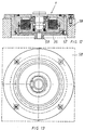
- Figures 2 and 3 show another embodiment in section and in plan view, it can be seen in FIG. 2 that, due to the interchangeability, the bottom 35 a thinner bottom 35 is used to achieve a lower installation height.
- FIGS. 4 to 11 show different variants of floor designs 35. It is essential that the bottom 35 in one piece as well as two parts can be trained; but it is always interchangeable.
- FIG. 4 it is shown that a two-part floor 35 is present, one Insert 45 is present, which is attached via a circlip 46; the blowing air passes into the housing via the connecting piece 30, enters a transverse channel 47 in the bottom and passes through an annular channel 48 which is formed as a puncture in radially obliquely inward outlet bores 49 which are approximately in the direction of the Longitudinal center axis are directed. From the blow-out holes 49, which obliquely after are directed downwards and inwards, moreover still branch obliquely upwards Blow holes 50 from.
- transverse channels 47 evenly on Circumferentially distributed in the ground and radiating in the ground extend and are connected in an air-tight manner to an annular channel 51.
- the insert 45 is also provided with an opening 52 in its central region, to possibly let coolant leak out, which from above into the housing of the clamping cylinder could penetrate.
- blow-out channels 49 are only inclined in the Blow-out bores open at the top, which consequently lead to the inside generate directed and obliquely upward air flow. Because if the Then retract the nipple 17 from its receptacle in the cylinder housing the nipple bore 43 becomes free and is in the blow-out bores 50th generated air jet directed from below upwards, cleaned.
- Figure 5 shows a further embodiment of a two-part floor 35, in which Bottom 35 in turn, an insert 53 is fitted, which is used there sealing.
- This insert 53 does not have the drain opening 52 mentioned above with reference to FIG. 4; otherwise the same explanations apply.
- FIG. 6 shows a two-part base 35 as a further exemplary embodiment an insert 54, which insert has the same function as that previously mentioned Insert 53, only that in addition to this insert a centering projection 55 is arranged, which is suitable in a corresponding center hole in a Hole grid pallet to intervene in order to position the entire clamping cylinder correctly Position the pallet.
- FIG. 7 shows a combination of the embodiment according to FIG. 4 and FIG. 6 because it can be seen that on the one hand there is an opening 52 to serve as a drain; there are also inflation bores 50 and centering insert 55 provided, which has already been mentioned in Figure 6.
- FIG. 8 shows a one-piece floor 35, which is only a central, central one Blow-out bore 50 forms in the direction of the nipple bore 43.
- FIG. 9 again shows a one-piece base, which, however, also has the previously mentioned centering projection 55 is provided.
- FIG. 10 shows a one-piece floor 35 with an opening 52 that acts as a drain is suitable and has obliquely downward blowout holes 50.
- FIG. 11 shows a two-part base 35 with an insert 56 which goes into the central center hole is pressed and the blow-out channels 49 defined, which in oblique blow-out bores 50 directed upward.
- Figures 12 and 13 show as a further embodiment that it is not is necessary for a solution, a quick release cylinder 1 to a milling machine table attach, as has been explained with reference to Figure 1, but in Figures 12 and 13 is an installation solution for the entire quick release cylinder in a receiving opening 57 of a machine table 58 or one Quick release plate is inserted.
Landscapes
- Engineering & Computer Science (AREA)
- Mechanical Engineering (AREA)
- Jigs For Machine Tools (AREA)
- Clamps And Clips (AREA)
- Actuator (AREA)
- Pistons, Piston Rings, And Cylinders (AREA)
- Automatic Assembly (AREA)
Applications Claiming Priority (4)
| Application Number | Priority Date | Filing Date | Title |
|---|---|---|---|
| DE19334040 | 1998-07-29 | ||
| DE19834040A DE19834040C2 (de) | 1998-07-29 | 1998-07-29 | Deckelloser Schnellspannzylinder |
| DE19834040 | 1998-07-29 | ||
| DE29813524U DE29813524U1 (de) | 1998-07-29 | 1998-07-29 | Schnellspannzylinder mit federkraftfreiem Deckenbereich |
Publications (3)
| Publication Number | Publication Date |
|---|---|
| EP0976481A2 true EP0976481A2 (fr) | 2000-02-02 |
| EP0976481A3 EP0976481A3 (fr) | 2002-11-27 |
| EP0976481B1 EP0976481B1 (fr) | 2003-10-01 |
Family
ID=26047744
Family Applications (1)
| Application Number | Title | Priority Date | Filing Date |
|---|---|---|---|
| EP99114661A Expired - Lifetime EP0976481B1 (fr) | 1998-07-29 | 1999-07-27 | Cylindre à serrer rapide sans couverture |
Country Status (3)
| Country | Link |
|---|---|
| EP (1) | EP0976481B1 (fr) |
| JP (1) | JP2000094251A (fr) |
| DE (3) | DE19834040C2 (fr) |
Cited By (10)
| Publication number | Priority date | Publication date | Assignee | Title |
|---|---|---|---|---|
| WO2004091849A1 (fr) * | 2003-04-15 | 2004-10-28 | Ssa System-Spann Ag | Cylindre a serrage rapide de conception modulaire |
| CN102189563A (zh) * | 2011-04-27 | 2011-09-21 | 长城汽车股份有限公司 | 一种汽车后搁物板切割定位工装总成 |
| ITTV20120129A1 (it) * | 2012-07-11 | 2014-01-12 | Almerino Canuto | Dispositivo di compensazione del disassamento in sistemi di bloccaggio automatici |
| CN104552087A (zh) * | 2015-01-12 | 2015-04-29 | 无锡亚中智能装备有限公司 | 多工位旋转工装夹具 |
| CN105033689A (zh) * | 2015-09-15 | 2015-11-11 | 沈阳飞机工业(集团)有限公司 | 一种新型定力压板装置 |
| CN107088666A (zh) * | 2017-06-07 | 2017-08-25 | 蔡崟 | 一种套筒径向孔加工装置 |
| CN107414119A (zh) * | 2017-06-07 | 2017-12-01 | 周梅 | 一种弹性夹紧钻孔装置 |
| DE102017223112A1 (de) | 2017-12-18 | 2019-06-19 | MTU Aero Engines AG | Gehäuseanordnung für eine Strömungsmaschine sowie Strömungsmaschinenanordnung mit einer solchen Gehäuseanordnung und Verfahren zum Herstellen der Gehäuseanordnung |
| CN114310406A (zh) * | 2022-01-18 | 2022-04-12 | 浙江金易达机械股份有限公司 | 一种偏心轴零部件加工偏心距调整定位工装 |
| CN114749699A (zh) * | 2022-06-15 | 2022-07-15 | 江苏泽恩机械科技有限公司 | 一种轴承沟道油孔加工装置 |
Families Citing this family (7)
| Publication number | Priority date | Publication date | Assignee | Title |
|---|---|---|---|---|
| DE19841928C2 (de) * | 1998-09-14 | 2003-03-20 | Stark Spannsysteme Gmbh Goetzi | Vorrichtung zur Beseitigung von Verunreinigungen an Schnellspanneinheiten |
| DE10245377A1 (de) * | 2002-09-28 | 2004-04-15 | Allmatic-Jakob Gmbh & Co. Spannsysteme Kg | Spannvorrichtung |
| DE10317346B4 (de) * | 2003-04-15 | 2020-02-20 | Andreas Maier Gmbh & Co. Kg | Halterungssystem einer Trägerplatte in Schnellspannzylindern |
| CN1293975C (zh) * | 2003-07-08 | 2007-01-10 | 吴炫隆 | 超薄型油压夹头 |
| DE102004006418A1 (de) * | 2004-02-09 | 2005-08-25 | Zero-Point-Systems Günther Stark GmbH | Schnellspannzylinder mit Sicherheitsvorrichtung gegen Blockierung |
| DE102006037709B4 (de) * | 2006-08-08 | 2014-02-13 | Schunk Gmbh & Co. Kg Spann- Und Greiftechnik | Schnellspanneinheit, Schnellspannsystem, Maschinen- oder Werkzeugteil und Ur- oder Umformwerkzeug |
| DE102018117667A1 (de) * | 2018-07-20 | 2020-01-23 | Georg Pichler GmbH | Spannvorrichtung |
Citations (1)
| Publication number | Priority date | Publication date | Assignee | Title |
|---|---|---|---|---|
| DE29615613U1 (de) | 1996-09-09 | 1997-08-28 | Stark, Emil, Götzis | Spannvorrichtung zum Spannen eines Schnellspannzylinders auf einer Trägerplatte für Bearbeitungsmaschinen |
Family Cites Families (3)
| Publication number | Priority date | Publication date | Assignee | Title |
|---|---|---|---|---|
| DE4307342C2 (de) * | 1993-03-09 | 1994-12-08 | Erowa Ag | Einrichtung zum positionsdefinierten Aufspannen eines Werkstücks am Arbeitsplatz einer Bearbeitungsmaschine |
| DE29722730U1 (de) * | 1997-12-23 | 1998-02-26 | Vischer & Bolli AG, Dübendorf | Spanneinrichtung zur Fixierung eines Einzugsnippels an einer Aufspannplatte |
| DE29804730U1 (de) | 1998-03-16 | 1998-05-20 | Vischer & Bolli AG, Dübendorf | Spanneinrichtung zur Fixierung einer mit einem Einzugsnippel versehenen Palette an einer Aufspannplatte |
-
1998
- 1998-07-29 DE DE19834040A patent/DE19834040C2/de not_active Expired - Fee Related
- 1998-07-29 DE DE29813524U patent/DE29813524U1/de not_active Expired - Lifetime
-
1999
- 1999-07-24 DE DE19934835A patent/DE19934835A1/de not_active Withdrawn
- 1999-07-27 EP EP99114661A patent/EP0976481B1/fr not_active Expired - Lifetime
- 1999-07-28 JP JP11214192A patent/JP2000094251A/ja active Pending
Patent Citations (1)
| Publication number | Priority date | Publication date | Assignee | Title |
|---|---|---|---|---|
| DE29615613U1 (de) | 1996-09-09 | 1997-08-28 | Stark, Emil, Götzis | Spannvorrichtung zum Spannen eines Schnellspannzylinders auf einer Trägerplatte für Bearbeitungsmaschinen |
Cited By (16)
| Publication number | Priority date | Publication date | Assignee | Title |
|---|---|---|---|---|
| WO2004091849A1 (fr) * | 2003-04-15 | 2004-10-28 | Ssa System-Spann Ag | Cylindre a serrage rapide de conception modulaire |
| CN102189563A (zh) * | 2011-04-27 | 2011-09-21 | 长城汽车股份有限公司 | 一种汽车后搁物板切割定位工装总成 |
| CN102189563B (zh) * | 2011-04-27 | 2013-02-13 | 长城汽车股份有限公司 | 一种汽车后搁物板切割定位工装总成 |
| US9863456B2 (en) | 2012-07-11 | 2018-01-09 | Almerino Canuto | Device for compensating offset in automatic locking systems |
| ITTV20120129A1 (it) * | 2012-07-11 | 2014-01-12 | Almerino Canuto | Dispositivo di compensazione del disassamento in sistemi di bloccaggio automatici |
| WO2014009201A1 (fr) * | 2012-07-11 | 2014-01-16 | Almerino Canuto | Dispositif pour compenser un décalage dans des systèmes de verrouillage automatique |
| CN104552087A (zh) * | 2015-01-12 | 2015-04-29 | 无锡亚中智能装备有限公司 | 多工位旋转工装夹具 |
| CN104552087B (zh) * | 2015-01-12 | 2016-08-17 | 无锡亚中智能装备有限公司 | 多工位旋转工装夹具 |
| CN105033689A (zh) * | 2015-09-15 | 2015-11-11 | 沈阳飞机工业(集团)有限公司 | 一种新型定力压板装置 |
| CN107088666A (zh) * | 2017-06-07 | 2017-08-25 | 蔡崟 | 一种套筒径向孔加工装置 |
| CN107414119A (zh) * | 2017-06-07 | 2017-12-01 | 周梅 | 一种弹性夹紧钻孔装置 |
| DE102017223112A1 (de) | 2017-12-18 | 2019-06-19 | MTU Aero Engines AG | Gehäuseanordnung für eine Strömungsmaschine sowie Strömungsmaschinenanordnung mit einer solchen Gehäuseanordnung und Verfahren zum Herstellen der Gehäuseanordnung |
| CN114310406A (zh) * | 2022-01-18 | 2022-04-12 | 浙江金易达机械股份有限公司 | 一种偏心轴零部件加工偏心距调整定位工装 |
| CN114310406B (zh) * | 2022-01-18 | 2023-03-07 | 浙江金易达机械股份有限公司 | 一种偏心轴零部件加工偏心距调整定位工装 |
| CN114749699A (zh) * | 2022-06-15 | 2022-07-15 | 江苏泽恩机械科技有限公司 | 一种轴承沟道油孔加工装置 |
| CN114749699B (zh) * | 2022-06-15 | 2022-08-12 | 江苏泽恩机械科技有限公司 | 一种轴承沟道油孔加工装置 |
Also Published As
| Publication number | Publication date |
|---|---|
| DE19934835A1 (de) | 2000-02-03 |
| DE19834040C2 (de) | 2002-01-17 |
| EP0976481B1 (fr) | 2003-10-01 |
| DE29813524U1 (de) | 1999-09-09 |
| JP2000094251A (ja) | 2000-04-04 |
| DE19834040A1 (de) | 2000-02-03 |
| EP0976481A3 (fr) | 2002-11-27 |
Similar Documents
| Publication | Publication Date | Title |
|---|---|---|
| EP0976481B1 (fr) | Cylindre à serrer rapide sans couverture | |
| EP0827805B1 (fr) | Dispositif de serrage pour serrer un cylindre de serrage rapide sur un plaque porteuse d'une machine d'usinage | |
| EP1268123B1 (fr) | Dispositif pour fixer de fa on amovible des pieces a usiner sur des dispositifs d'usinage | |
| EP3248733B1 (fr) | Dispositif de serrage | |
| EP1620228B1 (fr) | Cylindre de serrage rapide a montage simplifie | |
| DE4135418A1 (de) | Spannvorrichtung zum spannen einer aufspannplatte auf einer traegerplatte fuer bearbeitungsmaschinen | |
| DE20000895U1 (de) | Spanneinrichtung | |
| EP1615744B9 (fr) | Cylindre a serrage rapide de conception modulaire | |
| DE10002395B4 (de) | Spanneinrichtung | |
| DE19841928A1 (de) | Ausblas- und Ausspritzeinrichtung für Schnellspannzylinder mit Deckel | |
| EP1738864A2 (fr) | Dispositif de serrage | |
| EP0925872B1 (fr) | Dispositif de serrage pour la fixation d'un boulon de serrage sur une porte-pièce | |
| CH668021A5 (de) | Druckmittelbetaetigte spannvorrichtung zum spannen von werkzeugen oder werkstuecken. | |
| DE19920291A1 (de) | Kupplungssystem für den Anschluß maschinenseitiger Versorgungsleitungen für Medien aller Art inkl. elektrischer Leitungen zwichen Werkzeugmaschinen und daran angekoppeltem Werkstückträger | |
| EP0943396B1 (fr) | Dispositif pour fixer une pallette avec une cheville de connection sur une plate de montage | |
| DE102018119980A1 (de) | Spann- oder Greifeinrichtung | |
| EP1743733B1 (fr) | Raccorde rapide avec cylindre changeable | |
| DE102013218050A1 (de) | Spannvorrichtung zum Einspannen mindestens eines Spannnippels | |
| EP1620227B1 (fr) | Systeme de serrage comportant une piece d'adaptation | |
| DE29722730U1 (de) | Spanneinrichtung zur Fixierung eines Einzugsnippels an einer Aufspannplatte | |
| DE102020109587B4 (de) | Dehnspannvorrichtung, Spindelsystem, Verfahren und Anordnung zum automatisierten Spannen und Lösen eines Werkstücks und/oder Werkzeugs | |
| DE19861091A1 (de) | Spanneinrichtung zur Fixierung eines Werkstücks, einer Palette oder dergleichen an einem Maschinentisch | |
| AT410772B (de) | Halter zur befestigung eines mit einem haltezapfen versehenen werkstückes | |
| DE10118809A1 (de) | Schnellspanneinrichtung mit Späne- und Kühlmittelreinigung | |
| DE20219338U1 (de) | Spanneinrichtung zur Befestigung eines Einzugsbolzens mit Nuten |
Legal Events
| Date | Code | Title | Description |
|---|---|---|---|
| PUAI | Public reference made under article 153(3) epc to a published international application that has entered the european phase |
Free format text: ORIGINAL CODE: 0009012 |
|
| AK | Designated contracting states |
Kind code of ref document: A2 Designated state(s): AT BE CH CY DE DK ES FI FR GB GR IE IT LI LU MC NL PT SE |
|
| AX | Request for extension of the european patent |
Free format text: AL;LT;LV;MK;RO;SI |
|
| RAP1 | Party data changed (applicant data changed or rights of an application transferred) |
Owner name: STARK WERKZEUGGESELLSCHAFT MBH |
|
| RIN1 | Information on inventor provided before grant (corrected) |
Inventor name: STARK WERKZEUGGESELLSCHAFT MBH |
|
| RAP1 | Party data changed (applicant data changed or rights of an application transferred) |
Owner name: STARK SPANNSYSTEME GMBH |
|
| RIN1 | Information on inventor provided before grant (corrected) |
Inventor name: STARK SPANNSYSTEME GMBH |
|
| PUAL | Search report despatched |
Free format text: ORIGINAL CODE: 0009013 |
|
| AK | Designated contracting states |
Kind code of ref document: A3 Designated state(s): AT BE CH CY DE DK ES FI FR GB GR IE IT LI LU MC NL PT SE |
|
| AX | Request for extension of the european patent |
Free format text: AL;LT;LV;MK;RO;SI |
|
| 17P | Request for examination filed |
Effective date: 20021022 |
|
| GRAH | Despatch of communication of intention to grant a patent |
Free format text: ORIGINAL CODE: EPIDOS IGRA |
|
| GRAH | Despatch of communication of intention to grant a patent |
Free format text: ORIGINAL CODE: EPIDOS IGRA |
|
| AKX | Designation fees paid |
Designated state(s): AT BE CH CY DE DK ES FI FR GB GR IE IT LI LU MC NL PT SE |
|
| GRAA | (expected) grant |
Free format text: ORIGINAL CODE: 0009210 |
|
| AK | Designated contracting states |
Kind code of ref document: B1 Designated state(s): AT BE CH CY DE DK ES FI FR GB GR IE IT LI LU MC NL PT SE |
|
| PG25 | Lapsed in a contracting state [announced via postgrant information from national office to epo] |
Ref country code: NL Free format text: LAPSE BECAUSE OF FAILURE TO SUBMIT A TRANSLATION OF THE DESCRIPTION OR TO PAY THE FEE WITHIN THE PRESCRIBED TIME-LIMIT Effective date: 20031001 Ref country code: IT Free format text: LAPSE BECAUSE OF FAILURE TO SUBMIT A TRANSLATION OF THE DESCRIPTION OR TO PAY THE FEE WITHIN THE PRESCRIBED TIME-LIMIT;WARNING: LAPSES OF ITALIAN PATENTS WITH EFFECTIVE DATE BEFORE 2007 MAY HAVE OCCURRED AT ANY TIME BEFORE 2007. THE CORRECT EFFECTIVE DATE MAY BE DIFFERENT FROM THE ONE RECORDED. Effective date: 20031001 Ref country code: IE Free format text: LAPSE BECAUSE OF FAILURE TO SUBMIT A TRANSLATION OF THE DESCRIPTION OR TO PAY THE FEE WITHIN THE PRESCRIBED TIME-LIMIT Effective date: 20031001 Ref country code: GB Free format text: LAPSE BECAUSE OF FAILURE TO SUBMIT A TRANSLATION OF THE DESCRIPTION OR TO PAY THE FEE WITHIN THE PRESCRIBED TIME-LIMIT Effective date: 20031001 Ref country code: FR Free format text: LAPSE BECAUSE OF FAILURE TO SUBMIT A TRANSLATION OF THE DESCRIPTION OR TO PAY THE FEE WITHIN THE PRESCRIBED TIME-LIMIT Effective date: 20031001 Ref country code: FI Free format text: LAPSE BECAUSE OF FAILURE TO SUBMIT A TRANSLATION OF THE DESCRIPTION OR TO PAY THE FEE WITHIN THE PRESCRIBED TIME-LIMIT Effective date: 20031001 Ref country code: CY Free format text: LAPSE BECAUSE OF FAILURE TO SUBMIT A TRANSLATION OF THE DESCRIPTION OR TO PAY THE FEE WITHIN THE PRESCRIBED TIME-LIMIT Effective date: 20031001 |
|
| REG | Reference to a national code |
Ref country code: GB Ref legal event code: FG4D Free format text: NOT ENGLISH |
|
| REG | Reference to a national code |
Ref country code: CH Ref legal event code: EP |
|
| REG | Reference to a national code |
Ref country code: IE Ref legal event code: FG4D Free format text: GERMAN |
|
| REF | Corresponds to: |
Ref document number: 59907157 Country of ref document: DE Date of ref document: 20031106 Kind code of ref document: P |
|
| PG25 | Lapsed in a contracting state [announced via postgrant information from national office to epo] |
Ref country code: SE Free format text: LAPSE BECAUSE OF FAILURE TO SUBMIT A TRANSLATION OF THE DESCRIPTION OR TO PAY THE FEE WITHIN THE PRESCRIBED TIME-LIMIT Effective date: 20040101 Ref country code: GR Free format text: LAPSE BECAUSE OF FAILURE TO SUBMIT A TRANSLATION OF THE DESCRIPTION OR TO PAY THE FEE WITHIN THE PRESCRIBED TIME-LIMIT Effective date: 20040101 Ref country code: DK Free format text: LAPSE BECAUSE OF FAILURE TO SUBMIT A TRANSLATION OF THE DESCRIPTION OR TO PAY THE FEE WITHIN THE PRESCRIBED TIME-LIMIT Effective date: 20040101 |
|
| PG25 | Lapsed in a contracting state [announced via postgrant information from national office to epo] |
Ref country code: ES Free format text: LAPSE BECAUSE OF FAILURE TO SUBMIT A TRANSLATION OF THE DESCRIPTION OR TO PAY THE FEE WITHIN THE PRESCRIBED TIME-LIMIT Effective date: 20040112 |
|
| NLV1 | Nl: lapsed or annulled due to failure to fulfill the requirements of art. 29p and 29m of the patents act | ||
| REG | Reference to a national code |
Ref country code: CH Ref legal event code: NV Representative=s name: BOVARD AG PATENTANWAELTE |
|
| GBV | Gb: ep patent (uk) treated as always having been void in accordance with gb section 77(7)/1977 [no translation filed] |
Effective date: 20031001 |
|
| REG | Reference to a national code |
Ref country code: IE Ref legal event code: FD4D |
|
| PG25 | Lapsed in a contracting state [announced via postgrant information from national office to epo] |
Ref country code: LU Free format text: LAPSE BECAUSE OF NON-PAYMENT OF DUE FEES Effective date: 20040727 |
|
| PG25 | Lapsed in a contracting state [announced via postgrant information from national office to epo] |
Ref country code: MC Free format text: LAPSE BECAUSE OF NON-PAYMENT OF DUE FEES Effective date: 20040731 Ref country code: BE Free format text: LAPSE BECAUSE OF NON-PAYMENT OF DUE FEES Effective date: 20040731 |
|
| PLBE | No opposition filed within time limit |
Free format text: ORIGINAL CODE: 0009261 |
|
| STAA | Information on the status of an ep patent application or granted ep patent |
Free format text: STATUS: NO OPPOSITION FILED WITHIN TIME LIMIT |
|
| 26N | No opposition filed |
Effective date: 20040702 |
|
| EN | Fr: translation not filed | ||
| BERE | Be: lapsed |
Owner name: *STARK SPANNSYSTEME G.M.B.H. Effective date: 20040731 |
|
| BERE | Be: lapsed |
Owner name: *STARK SPANNSYSTEME G.M.B.H. Effective date: 20040731 |
|
| PG25 | Lapsed in a contracting state [announced via postgrant information from national office to epo] |
Ref country code: PT Free format text: LAPSE BECAUSE OF NON-PAYMENT OF DUE FEES Effective date: 20040301 |
|
| PGFP | Annual fee paid to national office [announced via postgrant information from national office to epo] |
Ref country code: CH Payment date: 20080724 Year of fee payment: 10 |
|
| PGFP | Annual fee paid to national office [announced via postgrant information from national office to epo] |
Ref country code: AT Payment date: 20080722 Year of fee payment: 10 |
|
| REG | Reference to a national code |
Ref country code: CH Ref legal event code: PL |
|
| PG25 | Lapsed in a contracting state [announced via postgrant information from national office to epo] |
Ref country code: LI Free format text: LAPSE BECAUSE OF NON-PAYMENT OF DUE FEES Effective date: 20090731 Ref country code: CH Free format text: LAPSE BECAUSE OF NON-PAYMENT OF DUE FEES Effective date: 20090731 |
|
| PG25 | Lapsed in a contracting state [announced via postgrant information from national office to epo] |
Ref country code: AT Free format text: LAPSE BECAUSE OF NON-PAYMENT OF DUE FEES Effective date: 20090727 |
|
| PGFP | Annual fee paid to national office [announced via postgrant information from national office to epo] |
Ref country code: DE Payment date: 20100731 Year of fee payment: 12 |
|
| PG25 | Lapsed in a contracting state [announced via postgrant information from national office to epo] |
Ref country code: DE Free format text: LAPSE BECAUSE OF NON-PAYMENT OF DUE FEES Effective date: 20120201 |
|
| REG | Reference to a national code |
Ref country code: DE Ref legal event code: R119 Ref document number: 59907157 Country of ref document: DE Effective date: 20120201 |