EP0976484A2 - Méthode de tournage de surfaces de rotation à des pièces à usiner - Google Patents
Méthode de tournage de surfaces de rotation à des pièces à usiner Download PDFInfo
- Publication number
- EP0976484A2 EP0976484A2 EP99112930A EP99112930A EP0976484A2 EP 0976484 A2 EP0976484 A2 EP 0976484A2 EP 99112930 A EP99112930 A EP 99112930A EP 99112930 A EP99112930 A EP 99112930A EP 0976484 A2 EP0976484 A2 EP 0976484A2
- Authority
- EP
- European Patent Office
- Prior art keywords
- finishing
- tool
- workpiece
- cutting insert
- turning
- Prior art date
- Legal status (The legal status is an assumption and is not a legal conclusion. Google has not performed a legal analysis and makes no representation as to the accuracy of the status listed.)
- Ceased
Links
Images


Classifications
-
- B—PERFORMING OPERATIONS; TRANSPORTING
- B23—MACHINE TOOLS; METAL-WORKING NOT OTHERWISE PROVIDED FOR
- B23B—TURNING; BORING
- B23B5/00—Turning-machines or devices specially adapted for particular work; Accessories specially adapted therefor
- B23B5/18—Turning-machines or devices specially adapted for particular work; Accessories specially adapted therefor for turning crankshafts, eccentrics, or cams, e.g. crankpin lathes
-
- B—PERFORMING OPERATIONS; TRANSPORTING
- B23—MACHINE TOOLS; METAL-WORKING NOT OTHERWISE PROVIDED FOR
- B23B—TURNING; BORING
- B23B1/00—Methods for turning or working essentially requiring the use of turning-machines; Use of auxiliary equipment in connection with such methods
-
- B—PERFORMING OPERATIONS; TRANSPORTING
- B23—MACHINE TOOLS; METAL-WORKING NOT OTHERWISE PROVIDED FOR
- B23D—PLANING; SLOTTING; SHEARING; BROACHING; SAWING; FILING; SCRAPING; LIKE OPERATIONS FOR WORKING METAL BY REMOVING MATERIAL, NOT OTHERWISE PROVIDED FOR
- B23D37/00—Broaching machines or broaching devices
- B23D37/005—Broaching machines or broaching devices for cylindrical workpieces, e.g. crankshafts
-
- B—PERFORMING OPERATIONS; TRANSPORTING
- B23—MACHINE TOOLS; METAL-WORKING NOT OTHERWISE PROVIDED FOR
- B23B—TURNING; BORING
- B23B2220/00—Details of turning, boring or drilling processes
- B23B2220/40—Peeling
Definitions
- the invention relates to a method for turning of rotating surfaces on workpieces, preferably on crankshafts, where the workpiece rotates during turning and with a disk-shaped tool that is staggered on the circumference Roughing and finishing cutting inserts are processed is used for finishing each cylindrical Several finishing inserts are used on the surface of the workpiece be that in time in the axial direction of the Remove material from the workpiece in the divided areas, and disk-shaped tool for performing the method.
- the finishing is a each cylindrical surface of a workpiece by one in the axial direction plunge turning of the workpiece.
- the divided plunge turning has the disadvantage that Flight deviations of the plunge cutters to the axis of rotation of the Lathe unfavorable on machining accuracy impact.
- the invention has for its object the method of initially mentioned type and the generic disc-shaped Train the tool so that when finishing a Every cylindrical surface of a workpiece has high machining accuracy is achieved.
- this object is achieved in the method by that for finishing each cylindrical surface longitudinal peeling of the workpiece from its two surface ends is carried out.
- a disk-shaped tool for carrying out the process, the on the circumference with offset roughing and finishing cutting inserts is provided for finishing each cylindrical surface of the workpiece at least one left and at least one right finishing insert with one for Cutting geometry designed for longitudinal peeling.
- Every roughing and finishing cutting insert is part of one Tool unit.
- finishing inserts for longitudinal peeling have the advantage that they are also used for finishing concave and convex Surfaces of a workpiece can be used.
- the invention is based on a drawing in which an embodiment is shown schematically, described in more detail.
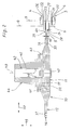
- a lathe 1 which is only partially shown, has between two chucks 2 a crankshaft 3 with several main (4) and connecting rod bearing journal 5 as a workpiece.
- the chuck 2 which is driven by a main drive (not shown) are driven, cause a rotary movement of the crankshaft 3 around the axis 6 of a connecting rod bearing journal 5 in the direction of the arrow 7.
- the axis 6 of the connecting rod bearing pin 5 thus lies in the axis of rotation 8 of the lathe 1.
- each main journal 4 lies the Crankshaft axis 9 in the axis of rotation 8 of the lathe 1.
- a disc-shaped Tool 10 is provided, which consists of a centering body 11, a supporting body 12, five times six tool units 13, 14, 15, 16, 17, 18 for roughing the main (4) and connecting rod bearing journals 5, five times two tool units 19, 20 for finishing the cheek projections 21, 22, 23, 24 and the undercuts 25, 26, 27, 28 the main (4) and connecting rod bearing journals 5 and two two tool units 29, 30 for finishing the main (4) and connecting rod journals 5 between the undercuts 25, 26, 27, 28.
- All tool units 13 to 20, 29, 30 are each one Screw 31 clamped on the outer surface 32 of the support body 12.
- the arrangement of the tool units 13 to 20, 29, 30 on the lateral surface 32 is chosen so that there are two identical gaps 33, 34 with a central angle of 15 °.
- the support body 12 is in a section 35 which the tool units 29, 30 and their adjacent areas 36, 37 detected with two lateral recesses 38, 39 executed.
- the lateral depth of the recesses 38, 39 results from the Width 40 of the tool units 29, 30.
- the centering body 11 and the support body 12 are by means of a A large number of screws 41 are firmly connected to one another.
- a clamping device 42 and two tongue and groove arrangements offset by 120 ° 43 establish a firm connection between the tool 10 and a tool spindle 44 ago.
- the clamping device 42 includes a clamping cylinder (not shown), one arranged axially displaceably in the tool spindle 44 Tensioning rod 45 with tensioning claws 46 and one from the centering body 11 received clamping bolt 47.
- the tool spindle 44 has a pivot axis 48 about which it is pivotable.
- the tool spindle 44 is driven by a swivel drive (not shown).
- the tool spindle 44 and its swivel drive are in one Longitudinal (double arrow 49) and face feed direction (double arrow 50) sliding support (not shown) arranged.
- the support always ensures that the swivel axis 48 is aligned with the axis of rotation 8 of the lathe 1.
- the tool spindle 44 is at the front with a tapered shoulder 51 formed, which serves to center the tool 10.
- the Centering body 11 has an annular shoulder 52 for this purpose an inner conical surface.
- the remaining tool units namely four times eight tool units 13 to 20 and once two tool units 29, 30 as a reserve to increase the working time of the tool 10.
- the embodiment is based on the fact that six tool units 13 to 18, each with a roughing cutting insert 53, 54, 55, 56, 57, 58 contain, one after the other the roughing a connecting rod bearing pin 5.
- a generatrix 62 includes one cylindrical surfaces 63 a.
- two tool units 29, 30 are used, which each represent a left and a right version.
- the left-hand tool unit 29 has a left (64), the right-hand tool unit 30 has a right finishing cutting insert 65.
- Both finishing cutting inserts 64, 65 have a cutting edge geometry for longitudinal peeling.
- the main cutting edge is the case for both finishing inserts 64, 65 66 at an angle of 10 ° to the axis of rotation 8 of the lathe 1 arranged.
- each size cutting insert 64, 65 has an angle of 2 ° to the axis of rotation 8 of the lathe 1.
- the left finishing cutting insert 64 takes the initial position for longitudinal peeling, as shown in FIG. 3 the cut through the finishing allowance that is still to be machined 68 shows.
- the left finishing cutting insert 64 leads in the longitudinal feed direction (Double arrow 49) longitudinal peeling in one right region 69 through, namely from a surface end 70 of the cylindrical surface 63 from up to that shown in Fig. 4 Position.
- the finishing machining allowance is made by longitudinal peeling 68 machined to the remaining finishing allowance 71.
- the remaining finishing allowance 71 is machined by the other surface end 72 of the cylindrical surface 63, wherein the right finishing cutting insert 65 the plunge and Longitudinal peeling in the left area 73 analogous to the working method of the left finishing cutting insert 64.
Landscapes
- Engineering & Computer Science (AREA)
- Mechanical Engineering (AREA)
- Turning (AREA)
- Milling Processes (AREA)
Applications Claiming Priority (2)
| Application Number | Priority Date | Filing Date | Title |
|---|---|---|---|
| DE19833363 | 1998-07-24 | ||
| DE1998133363 DE19833363B4 (de) | 1998-07-24 | 1998-07-24 | Verfahren zur Drehbearbeitung von Rotationsflächen an Werkstücken, vorzugsweise an Kurbelwellen, und scheibenförmiges Werkzeug zur Durchführung des Verfahrens |
Publications (2)
| Publication Number | Publication Date |
|---|---|
| EP0976484A2 true EP0976484A2 (fr) | 2000-02-02 |
| EP0976484A3 EP0976484A3 (fr) | 2002-11-13 |
Family
ID=7875189
Family Applications (1)
| Application Number | Title | Priority Date | Filing Date |
|---|---|---|---|
| EP99112930A Ceased EP0976484A3 (fr) | 1998-07-24 | 1999-07-05 | Méthode de tournage de surfaces de rotation à des pièces à usiner |
Country Status (2)
| Country | Link |
|---|---|
| EP (1) | EP0976484A3 (fr) |
| DE (1) | DE19833363B4 (fr) |
Cited By (4)
| Publication number | Priority date | Publication date | Assignee | Title |
|---|---|---|---|---|
| WO2003022497A1 (fr) * | 2001-09-11 | 2003-03-20 | Boehringer Werkzeugmaschinen Gmbh | Procede d'usinage par enlevement de copeaux sans deviation, de surfaces a symetrie de revolution |
| WO2006002862A1 (fr) * | 2004-07-06 | 2006-01-12 | Kennametal Inc. | Outil et dispositif pour usiner des pieces a usiner |
| EP1710035A1 (fr) | 2005-04-04 | 2006-10-11 | Ulrich Huperz Schweisstechnik GmbH & Co. KG | Dispositif et procédé d'usinage réduisant les bavures |
| DE102015009481A1 (de) * | 2015-07-20 | 2017-01-26 | Niles-Simmons Industrieanlagen Gmbh | Verfahren und Vorrichtung zum Feinbearbeiten von vorbearbeiteten Lagersitzen der Hauptlager und Hublager von Kurbelwellen |
Families Citing this family (4)
| Publication number | Priority date | Publication date | Assignee | Title |
|---|---|---|---|---|
| RU2198766C2 (ru) * | 2000-08-29 | 2003-02-20 | Открытое акционерное общество "Научно-производственное объединение "Сатурн" | Способ обработки деталей типа коленчатых валов |
| DE10235957B4 (de) | 2002-08-06 | 2005-01-20 | Hegenscheidt-Mfd Gmbh & Co. Kg | Verfahren zum Fertigbearbeiten von Kurbelwellen für Kraftfahrzeugmotoren |
| AT517878B1 (de) | 2015-11-06 | 2017-11-15 | Ge Jenbacher Gmbh & Co Og | Pleuel |
| DE102016014496B4 (de) * | 2016-12-05 | 2019-01-10 | Audi Ag | Drehwerkzeug, insbesondere Drehräumwerkzeug |
Citations (1)
| Publication number | Priority date | Publication date | Assignee | Title |
|---|---|---|---|---|
| DE4119162C1 (fr) | 1991-06-11 | 1992-05-21 | Gebr. Heller Maschinenfabrik Gmbh, 7440 Nuertingen, De |
Family Cites Families (7)
| Publication number | Priority date | Publication date | Assignee | Title |
|---|---|---|---|---|
| US4018112A (en) * | 1974-11-29 | 1977-04-19 | Kennametal Inc. | Machine tool having a special indexable turret and method of operation |
| DE2546171A1 (de) * | 1975-10-15 | 1977-09-01 | Kieserling & Albrecht | Verfahren zum dreh-schaelen von runden werkstuecken |
| EP0134383A1 (fr) * | 1983-09-05 | 1985-03-20 | GFM Gesellschaft für Fertigungstechnik und Maschinenbau Gesellschaft m.b.H. | Procédé d'usinage de vilebrequins ou de pièces analogues |
| DE3924884C3 (de) * | 1989-07-27 | 1998-10-22 | Sandvik Gmbh | Werkzeug zum spanabhebenden Bearbeiten von Werkstücken |
| DE4135681C3 (de) * | 1991-10-30 | 1999-02-11 | Heller Geb Gmbh Maschf | Verfahren zur spanenden Bearbeitung rotationssymmetrischer Werkstückflächen, insbesondere von Kurbelwellen, sowie Werkzeug zur Durchführung eines solchen Verfahrens |
| DE4416773A1 (de) * | 1994-05-10 | 1995-11-16 | Mannesmann Ag | Vorrichtung zum spanenden Oberflächenbearbeiten |
| JPH08215902A (ja) * | 1995-02-13 | 1996-08-27 | Toyoda Mach Works Ltd | クランク軸の旋削装置 |
-
1998
- 1998-07-24 DE DE1998133363 patent/DE19833363B4/de not_active Expired - Fee Related
-
1999
- 1999-07-05 EP EP99112930A patent/EP0976484A3/fr not_active Ceased
Patent Citations (1)
| Publication number | Priority date | Publication date | Assignee | Title |
|---|---|---|---|---|
| DE4119162C1 (fr) | 1991-06-11 | 1992-05-21 | Gebr. Heller Maschinenfabrik Gmbh, 7440 Nuertingen, De |
Cited By (6)
| Publication number | Priority date | Publication date | Assignee | Title |
|---|---|---|---|---|
| WO2003022497A1 (fr) * | 2001-09-11 | 2003-03-20 | Boehringer Werkzeugmaschinen Gmbh | Procede d'usinage par enlevement de copeaux sans deviation, de surfaces a symetrie de revolution |
| US7216571B2 (en) | 2001-09-11 | 2007-05-15 | Boehringer Werkzeugmaschinen Gmbh | Process for twist-free steel cutting of rotational symmetrical surfaces |
| WO2006002862A1 (fr) * | 2004-07-06 | 2006-01-12 | Kennametal Inc. | Outil et dispositif pour usiner des pieces a usiner |
| EP1710035A1 (fr) | 2005-04-04 | 2006-10-11 | Ulrich Huperz Schweisstechnik GmbH & Co. KG | Dispositif et procédé d'usinage réduisant les bavures |
| DE102015009481A1 (de) * | 2015-07-20 | 2017-01-26 | Niles-Simmons Industrieanlagen Gmbh | Verfahren und Vorrichtung zum Feinbearbeiten von vorbearbeiteten Lagersitzen der Hauptlager und Hublager von Kurbelwellen |
| DE102015009481B4 (de) * | 2015-07-20 | 2017-05-24 | Niles-Simmons Industrieanlagen Gmbh | Verfahren und Vorrichtung zum Feinbearbeiten von vorbearbeiteten Lagersitzen der Hauptlager und Hublager von Kurbelwellen |
Also Published As
| Publication number | Publication date |
|---|---|
| DE19833363A1 (de) | 2000-01-27 |
| DE19833363B4 (de) | 2010-07-29 |
| EP0976484A3 (fr) | 2002-11-13 |
Similar Documents
| Publication | Publication Date | Title |
|---|---|---|
| EP0182290A2 (fr) | Tête de fraisage | |
| EP0542026B1 (fr) | Procédé d'usinage de surface à symétrie de rotation, en particulier vilebrequin, ainsi que outil pour la réalisation d'un tel procédé | |
| EP1286802A1 (fr) | Fraise trois tailles | |
| EP4306251B1 (fr) | Outil et procédé d'ébavurage et/ou de chanfreinage par enlèvement de copeaux d'une denture de pièce usinée comprenant une pluralité de dents de pièce usinée | |
| DE19833363B4 (de) | Verfahren zur Drehbearbeitung von Rotationsflächen an Werkstücken, vorzugsweise an Kurbelwellen, und scheibenförmiges Werkzeug zur Durchführung des Verfahrens | |
| AT398049B (de) | Werkzeugträger zum wirbeln bzw. schälen von aussengewinden, schnecken und profilen | |
| DE3523274C3 (de) | Verfahren und Vorrichtung zur spanenden Bearbeitung von rotationssymmetrischen Werkstückflächen durch Drehräumen | |
| DE102006014972B4 (de) | Kombiniertes Bearbeitungsverfahren und Bearbeitungseinrichtung | |
| EP0685283B1 (fr) | Procédé d'usinage d'essieux montés et machine pour l'usinage d'essieux montés | |
| EP0841116B1 (fr) | Méthode de travail de surfaces de pièces symétriques en rotation et outil employé | |
| DE10245071B4 (de) | Maschine zum Schruppen und Schlichten der Lagerzapfen von Kurbelwellen | |
| DE19646124C1 (de) | Spannvorrichtung für ringförmige Werkstückpakete | |
| DE2429145A1 (de) | Vorrichtung zum abscheiden von material von fahrzeugreifen fuer die runderneuerung | |
| DE3504296C2 (fr) | ||
| DE3333243A1 (de) | Mehrspindel-drehautomat | |
| EP0119236B1 (fr) | Tour automatique a broches multiples | |
| DE19962792C1 (de) | Verfahren und Vorrichtung zum Schleifen von Gelenksternen | |
| DE2217288C3 (de) | Einrichtung an einer Drehmaschine zum Herstellen von Nuten an drehsymmetrischen Werkstücken | |
| DE29606165U1 (de) | Fasenfräser | |
| AT526662B1 (de) | Vorrichtung zum Bearbeiten von Rändern von flächigen Werkstücken | |
| DE1817257A1 (de) | Raeumvorrichtung | |
| DE2131709A1 (de) | Maschine zum Scharfschleifen von Gesteinsbohrern | |
| DE3340830A1 (de) | Verfahren und vorrichtung zum raeumen der umfangsflaeche eines runden werkstuecks | |
| EP0972597A2 (fr) | Centre pour utilisation avec un tour | |
| DE9200400U1 (de) | Bearbeitungsvorrichtung |
Legal Events
| Date | Code | Title | Description |
|---|---|---|---|
| PUAI | Public reference made under article 153(3) epc to a published international application that has entered the european phase |
Free format text: ORIGINAL CODE: 0009012 |
|
| AK | Designated contracting states |
Kind code of ref document: A2 Designated state(s): AT BE CH CY DE DK ES FI FR GB GR IE IT LI LU MC NL PT SE |
|
| AX | Request for extension of the european patent |
Free format text: AL;LT;LV;MK;RO;SI |
|
| PUAL | Search report despatched |
Free format text: ORIGINAL CODE: 0009013 |
|
| AK | Designated contracting states |
Kind code of ref document: A3 Designated state(s): AT BE CH CY DE DK ES FI FR GB GR IE IT LI LU MC NL PT SE |
|
| AX | Request for extension of the european patent |
Free format text: AL;LT;LV;MK;RO;SI |
|
| RIC1 | Information provided on ipc code assigned before grant |
Free format text: 7B 23D 37/00 A, 7B 23B 5/18 B, 7B 23B 1/00 B |
|
| RAP1 | Party data changed (applicant data changed or rights of an application transferred) |
Owner name: HEGENSCHEIDT-MFD GMBH & CO. KG |
|
| 17P | Request for examination filed |
Effective date: 20021127 |
|
| AKX | Designation fees paid |
Designated state(s): DE ES FR GB IT PT |
|
| AXX | Extension fees paid |
Extension state: SI Payment date: 20030116 |
|
| 17Q | First examination report despatched |
Effective date: 20040927 |
|
| RAP1 | Party data changed (applicant data changed or rights of an application transferred) |
Owner name: NILES-SIMMONS INDUSTRIEANLAGEN GMBH |
|
| STAA | Information on the status of an ep patent application or granted ep patent |
Free format text: STATUS: THE APPLICATION HAS BEEN REFUSED |
|
| 18R | Application refused |
Effective date: 20091227 |