EP0976492B1 - Schaftfräser mit Hartmetallschneiden - Google Patents
Schaftfräser mit Hartmetallschneiden Download PDFInfo
- Publication number
- EP0976492B1 EP0976492B1 EP99113109A EP99113109A EP0976492B1 EP 0976492 B1 EP0976492 B1 EP 0976492B1 EP 99113109 A EP99113109 A EP 99113109A EP 99113109 A EP99113109 A EP 99113109A EP 0976492 B1 EP0976492 B1 EP 0976492B1
- Authority
- EP
- European Patent Office
- Prior art keywords
- head
- milling cutter
- cutting edges
- shaft
- hard metal
- Prior art date
- Legal status (The legal status is an assumption and is not a legal conclusion. Google has not performed a legal analysis and makes no representation as to the accuracy of the status listed.)
- Expired - Lifetime
Links
Images


Classifications
-
- B—PERFORMING OPERATIONS; TRANSPORTING
- B22—CASTING; POWDER METALLURGY
- B22F—WORKING METALLIC POWDER; MANUFACTURE OF ARTICLES FROM METALLIC POWDER; MAKING METALLIC POWDER; APPARATUS OR DEVICES SPECIALLY ADAPTED FOR METALLIC POWDER
- B22F3/00—Manufacture of workpieces or articles from metallic powder characterised by the manner of compacting or sintering; Apparatus specially adapted therefor ; Presses and furnaces
- B22F3/22—Manufacture of workpieces or articles from metallic powder characterised by the manner of compacting or sintering; Apparatus specially adapted therefor ; Presses and furnaces for producing castings from a slip
- B22F3/225—Manufacture of workpieces or articles from metallic powder characterised by the manner of compacting or sintering; Apparatus specially adapted therefor ; Presses and furnaces for producing castings from a slip by injection molding
-
- B—PERFORMING OPERATIONS; TRANSPORTING
- B22—CASTING; POWDER METALLURGY
- B22F—WORKING METALLIC POWDER; MANUFACTURE OF ARTICLES FROM METALLIC POWDER; MAKING METALLIC POWDER; APPARATUS OR DEVICES SPECIALLY ADAPTED FOR METALLIC POWDER
- B22F7/00—Manufacture of composite layers, workpieces, or articles, comprising metallic powder, by sintering the powder, with or without compacting wherein at least one part is obtained by sintering or compression
- B22F7/06—Manufacture of composite layers, workpieces, or articles, comprising metallic powder, by sintering the powder, with or without compacting wherein at least one part is obtained by sintering or compression of composite workpieces or articles from parts, e.g. to form tipped tools
- B22F7/062—Manufacture of composite layers, workpieces, or articles, comprising metallic powder, by sintering the powder, with or without compacting wherein at least one part is obtained by sintering or compression of composite workpieces or articles from parts, e.g. to form tipped tools involving the connection or repairing of preformed parts
-
- B—PERFORMING OPERATIONS; TRANSPORTING
- B23—MACHINE TOOLS; METAL-WORKING NOT OTHERWISE PROVIDED FOR
- B23C—MILLING
- B23C5/00—Milling-cutters
- B23C5/02—Milling-cutters characterised by the shape of the cutter
- B23C5/10—Shank-type cutters, i.e. with an integral shaft
-
- B—PERFORMING OPERATIONS; TRANSPORTING
- B23—MACHINE TOOLS; METAL-WORKING NOT OTHERWISE PROVIDED FOR
- B23P—METAL-WORKING NOT OTHERWISE PROVIDED FOR; COMBINED OPERATIONS; UNIVERSAL MACHINE TOOLS
- B23P15/00—Making specific metal objects by operations not covered by a single other subclass or a group in this subclass
- B23P15/28—Making specific metal objects by operations not covered by a single other subclass or a group in this subclass cutting tools
- B23P15/34—Making specific metal objects by operations not covered by a single other subclass or a group in this subclass cutting tools milling cutters
-
- B—PERFORMING OPERATIONS; TRANSPORTING
- B27—WORKING OR PRESERVING WOOD OR SIMILAR MATERIAL; NAILING OR STAPLING MACHINES IN GENERAL
- B27G—ACCESSORY MACHINES OR APPARATUS FOR WORKING WOOD OR SIMILAR MATERIALS; TOOLS FOR WORKING WOOD OR SIMILAR MATERIALS; SAFETY DEVICES FOR WOOD WORKING MACHINES OR TOOLS
- B27G15/00—Boring or turning tools; Augers
-
- B—PERFORMING OPERATIONS; TRANSPORTING
- B22—CASTING; POWDER METALLURGY
- B22F—WORKING METALLIC POWDER; MANUFACTURE OF ARTICLES FROM METALLIC POWDER; MAKING METALLIC POWDER; APPARATUS OR DEVICES SPECIALLY ADAPTED FOR METALLIC POWDER
- B22F5/00—Manufacture of workpieces or articles from metallic powder characterised by the special shape of the product
- B22F2005/001—Cutting tools, earth boring or grinding tool other than table ware
-
- B—PERFORMING OPERATIONS; TRANSPORTING
- B22—CASTING; POWDER METALLURGY
- B22F—WORKING METALLIC POWDER; MANUFACTURE OF ARTICLES FROM METALLIC POWDER; MAKING METALLIC POWDER; APPARATUS OR DEVICES SPECIALLY ADAPTED FOR METALLIC POWDER
- B22F2998/00—Supplementary information concerning processes or compositions relating to powder metallurgy
- B22F2998/10—Processes characterised by the sequence of their steps
-
- B—PERFORMING OPERATIONS; TRANSPORTING
- B23—MACHINE TOOLS; METAL-WORKING NOT OTHERWISE PROVIDED FOR
- B23C—MILLING
- B23C2222/00—Materials of tools or workpieces composed of metals, alloys or metal matrices
- B23C2222/28—Details of hard metal, i.e. cemented carbide
-
- B—PERFORMING OPERATIONS; TRANSPORTING
- B23—MACHINE TOOLS; METAL-WORKING NOT OTHERWISE PROVIDED FOR
- B23C—MILLING
- B23C2226/00—Materials of tools or workpieces not comprising a metal
- B23C2226/61—Plastics not otherwise provided for, e.g. nylon
Definitions
- the present invention relates to a End mill according to the preamble of claim 1 and how e.g. is known from DE-U-29 701 161.
- End mills with hard metal cutting edges are used especially for used wood and plastic processing, for example for the machining of chipboard, since there normal cutter cuts would dull very quickly.
- End mills with carbide cutting edges are known to be in executed in such a way that the end mill body made of tool steel manufactured and the carbide cutting edges open or be soldered in. It is also known, the end mill body To produce in two parts, namely from a shaft part and a headboard that screwed together or on are connected in any other way, especially if the head part has a larger diameter, for example as a drill serving end mills.
- hard metal cutting edges have an appropriate size so that they can be soldered in can have the necessary support and also with regard to mechanical strength necessary for their brittleness to have. They are usually plate-shaped. This too conditionally, especially on the rake face, in practice quite a bit of sanding.
- the invention has for its object a possibility create end mills by avoiding grinding to be able to manufacture with carbide cutting edges more cost-effectively.
- the solution according to the invention is that the area of the tool body encompassing the cutting edge or the cutting edges made entirely of hard metal and with a Positive connection for connection to the rest of the tool body part, which can be made of tool steel, is formed, the peculiarity is that including this tool body part made of hard metal the molded cutting edges by injection molding produced as a blank and then on the cutting areas is ground.
- the part of the tool body shaped in this way can be on the cutting edge areas already in the raw form with the necessary free cuts be trained.
- the resulting benefits are that on the one hand the tool body as a whole needs to be less massive than with conventional end mills with a relatively large head diameter and that also undercuts be designed at the edge areas can that the cutting surface to be ground much smaller than conventional, in tool body made of tool steel hard metal plates soldered in and serving as cutting edges.
- heads of end mills made entirely of hard metal and with an internally threaded hole be trained, in which of those with a corresponding Threaded shank then equipped screwed in and glued to secure it, for example can.
- Routers can also be manufactured in this way, by a part surrounding the cutting edge than with a molded one Rod-shaped block with dovetail profile trained and provided with a corresponding counter profile Shaft can be attached, then one Adhesive connection is possible and the previous soldering one Cutting plate can be omitted.
- 1 and 2 show one designed as a drill End mill for drilling relatively large round recesses in Pressboard, such as in the furniture industry for milling out openings for hinges and the like is common.
- the milling cutter shown consists of a shank 1 and a Head 2.
- the head 2 is together with the molded cutting edges 3a, 3b and 3c made from one piece of hard metal and with an internally threaded bore 4, into which a threaded pin 5 of the shaft 1 is screwed in.
- the shaft 1 with the threaded pin 5 is made of tool steel.
- the head 2 with the cutting edges 3a, 3b and 3c is upwards already mentioned injection molding process manufactured as a sintered blank, then sintered and finally by grinding the Cutting has been completed.
- the cutting edges include the illustrated embodiment, as in Fig. 2 more in Individual emerges two outer pre-cutting edges 3a, two main cutting edges 3b and a drill bit 3c.
- the main ' cut 3b are against the drill tip 3c and the pre-cutter 3a axially reset.
- the functions of this cutting are known; the pre-cutters 3a give a precise Cut at the edge of the hole without fraying and the main cutting edges 3b serve to clear the material between that of the Drill tip 3c produced core drilling and that of the pre-cutters 3a generated edge cut.
- the shaft 1 is preferably in with its threaded pin 5 the threaded hole 4 glued so that all cavities with Resin adhesive 6 or the like are filled.
- the head 2 is opposite conventional heads of such tool bodies very much leaner and less massive, as shown in FIG. 1 looks, both in axial extent and how to look Fig. 2 sees the circumferential extent of the two Cut 3b assigned areas.
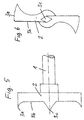
- FIG. 3 and 4 show in view and in section a router, consisting of a shaft 11 with a front part 12 in the form of a cylinder segment with an integrated dovetail groove 13 (see cross section according to FIG. 4), and one with a cutting edge hard metal body 21 with a Cutting edge 22, an incorporated flute 23 and a rear molded dovetail 24, which in the dovetail groove 13 engages and preferably glued there is.
- the shaft 11 again consists of tool steel, is the hard metal body 21 in turn in the injection molding process mentioned produced as a blank and then after sintering connected to the shaft by gluing, whereby by the interaction the dovetail groove 13 and the dovetail 24 a positive connection is established.
- the cutting edge 22 can be connected to the before or after the connection Shaft 11 be ground.
- FIGS. 5 and 6 show a variant of that in FIGS. 1 and 2 already illustrated embodiment of a drill, the radial arms of the head 2 are made even slimmer and the main cutting edges 3b on the outside flowing into the rough cutters 3a pass over.
Landscapes
- Mechanical Engineering (AREA)
- Engineering & Computer Science (AREA)
- Life Sciences & Earth Sciences (AREA)
- Manufacturing & Machinery (AREA)
- Chemical & Material Sciences (AREA)
- Materials Engineering (AREA)
- Composite Materials (AREA)
- Wood Science & Technology (AREA)
- Forests & Forestry (AREA)
- Milling Processes (AREA)
- Drilling Tools (AREA)
- Earth Drilling (AREA)
- Powder Metallurgy (AREA)
Description
- Fig. 1
- einen Schaftfräser nach der Erfindung in teilweise axial geschnittener Ansicht,
- Fig. 2
- eine Stirnansicht des Schaftfräsers nach Fig. 1,
- Fig. 3
- eine Ansicht eines Oberfräsers nach der Erfindung, und
- Fig. 4
- einen Querschnitt längs der Linie IV - IV durch den Oberfräser nach Fig. 3,
- Fig. 5
- eine weitere Ausführungsform eines als Bohrer dienenden Schaftfräsers in Seitenansicht, und
- Fig. 6
- den Fräser nach Fig. 5 in Stirnansicht.
Claims (7)
- Schaftfräser mit Hartmetallschneiden, bestehend aus einem Schaft (1) aus Werkzeugstahl und einem damit formschlüssig verbundenen Kopf (2), dadurch gekennzeichnet daß der Kopf als integrierter Werkzeugkörper mit angeformten Schneiden (3a, 3b, 3c) insgesamt aus Hartmetall hergestellt ist und zwar in Form einer zunächst im Spritzgießverfahren aus pulverisiertem Hartmetallwerkstoff mit plastifizierendem Bindemittel hergestellten Rohlings, der nach dem Sintern durch Anschleifen der Schneiden fertig bearbeitet wurde.
- Schaftfräser nach Anspruch 1, wobei die Formschlußverbindung zwischen Schaft (1) und Kopf durch ein am Schaft gebildetes Außengewinde und ein im Kopf gebildetes Innengewinde hergestellt ist.
- Schaftfräser nach Anspruch 1 oder 2, wobei der Kopf (2) als Bohrkopf mit einer zentrischen Bohrspitze (3c) und mindestens zwei radial von einem mittigen Nabenbereich wegragenden schlanken Armen mit Schneidkanten (3b) und äußeren Vorschneidkanten (3a) ausgebildet ist.
- Schaftfräser nach Anspruch 3, wobei die Hauptschneiden (3b) der Arme des Kopfes (2) fließend in die Vorschneidekanten (3a) übergehen.
- Schaftfräser nach Anspruch 1, wobei der Kopf als Oberfräsenschneidenkörper (21) mit angeformter Frässchneide (22) und Spannut (23) ausgebildet ist, und wobei die Formschlußverbindung durch ein rückseitig an den Oberfräsenschneiden körper (21) angeformtes und in eine entsprechende Längsnut (13) des Schaftvorderteils (12) eingreifendes Profil (24) gebildet ist.
- Schaftfräser nach Anspruch 5, wobei die Nut (13) als Schwalbenschwanznut und das Profil (24) als Schwalbenschwanzprofil ausgebildet ist.
- Schaftfräser nach einem der Ansprüche 1 bis 6, wobei die Formschlußverbindung zwischen Kopf (2) und Schaft (1) außerdem durch Verkleben gesichert ist.
Applications Claiming Priority (2)
| Application Number | Priority Date | Filing Date | Title |
|---|---|---|---|
| DE19832551A DE19832551A1 (de) | 1998-07-21 | 1998-07-21 | Schaftfräser mit Hartmetallschneiden |
| DE19832551 | 1998-07-21 |
Publications (2)
| Publication Number | Publication Date |
|---|---|
| EP0976492A1 EP0976492A1 (de) | 2000-02-02 |
| EP0976492B1 true EP0976492B1 (de) | 2001-12-05 |
Family
ID=7874661
Family Applications (1)
| Application Number | Title | Priority Date | Filing Date |
|---|---|---|---|
| EP99113109A Expired - Lifetime EP0976492B1 (de) | 1998-07-21 | 1999-07-07 | Schaftfräser mit Hartmetallschneiden |
Country Status (3)
| Country | Link |
|---|---|
| EP (1) | EP0976492B1 (de) |
| AT (1) | ATE209998T1 (de) |
| DE (1) | DE19832551A1 (de) |
Families Citing this family (6)
| Publication number | Priority date | Publication date | Assignee | Title |
|---|---|---|---|---|
| DE10161823A1 (de) * | 2001-12-15 | 2003-06-26 | Tigra Hartstoff Gmbh | Zylinderkopfbohrer oder ähnliches Werkzeug mit Hartmetallschneiden |
| AT505198B1 (de) * | 2007-05-11 | 2009-09-15 | Boehlerit Gmbh & Co Kg | Schneidwerkzeug |
| US8727679B2 (en) * | 2009-09-10 | 2014-05-20 | Techtronic Power Tools Technology Limited | Wood boring bit |
| EP2596887B1 (de) | 2011-11-23 | 2019-01-23 | Sandvik Intellectual Property AB | Schneidwerkzeug mit austauschbarem Einsatzsitzelement |
| DE102014101656B4 (de) | 2014-02-11 | 2025-08-07 | Adolf Würth Gmbh & Co Kg | Kombinierte Reiß- und Spanvorrichtung zum Locherzeugen in einem Untergrund |
| EP4197671A1 (de) * | 2021-12-17 | 2023-06-21 | Michael Johannes Müller | Verfahren zur herstellung eines werkzeugs oder eines bearbeitungsaktiven teils eines werkzeugs und nach diesem verfahren hergestelltes werkzeug |
Family Cites Families (7)
| Publication number | Priority date | Publication date | Assignee | Title |
|---|---|---|---|---|
| US4239427A (en) * | 1979-09-28 | 1980-12-16 | Black & Decker Inc. | Boring tool |
| DE3523452C1 (en) * | 1985-07-01 | 1987-01-08 | Lvt Loet Und Verschleisstechni | Milling spindle with a milling head brazed to a shank and a method for producing it |
| DE8705288U1 (de) * | 1987-04-09 | 1987-05-27 | Carl Hurth Maschinen- und Zahnradfabrik GmbH & Co, 8000 München | Fräser, insbesondere Stirnfräser, und dafür geeigneter Aufnahmeschaft zur voreinstellbaren Aufnahme in einer Werkzeugmaschine |
| US5221166A (en) * | 1991-07-31 | 1993-06-22 | Enderes Tool Co., Inc. | Spade-type drill bit apparatus and method |
| JPH06315835A (ja) * | 1993-05-06 | 1994-11-15 | Sumitomo Electric Ind Ltd | ヘリカルエンドミル用ねじれチップ及びその製造方法 |
| DE9417778U1 (de) * | 1994-11-05 | 1994-12-15 | wolfcraft GmbH, 56745 Weibern | Forstner-Bohrer |
| DE29701161U1 (de) * | 1997-01-24 | 1998-05-28 | FAMAG-Werkzeugfabrik Friedr. Aug. Mühlhoff, 42855 Remscheid | Zylinderkopfbohrer |
-
1998
- 1998-07-21 DE DE19832551A patent/DE19832551A1/de not_active Withdrawn
-
1999
- 1999-07-07 AT AT99113109T patent/ATE209998T1/de not_active IP Right Cessation
- 1999-07-07 EP EP99113109A patent/EP0976492B1/de not_active Expired - Lifetime
Also Published As
| Publication number | Publication date |
|---|---|
| EP0976492A1 (de) | 2000-02-02 |
| DE19832551A1 (de) | 2000-01-27 |
| ATE209998T1 (de) | 2001-12-15 |
Similar Documents
| Publication | Publication Date | Title |
|---|---|---|
| DE60012766T2 (de) | Bohrer, bohrerspitze und deren herstellung | |
| DE60132455T2 (de) | Drehendes werkzeug mit einem ersetzbaren schneideinsatz an einem ende | |
| EP0674560B1 (de) | Bohrer mit austauschbarem schneideinsatz | |
| DE69729945T2 (de) | Fräser | |
| DE69919032T2 (de) | Werkzeug und schneidkopf für spanabhebende bearbeitung | |
| DE4115030C1 (de) | ||
| EP0084607A2 (de) | Fräswerkzeug | |
| DE69510794T2 (de) | Bohrwerkzeug mit ausnehmungen für abgerundete schneideinsätze | |
| EP1147841B1 (de) | Schneidplatte und Zerspanungswerkzeug zum Fräsen | |
| EP0976492B1 (de) | Schaftfräser mit Hartmetallschneiden | |
| DE3321110C2 (de) | ||
| DE10359854A1 (de) | Zylinderkopfbohrer mit Hartmetallschneiden und Kunststoffschaft | |
| DE4127509C2 (de) | ||
| EP1738849B1 (de) | Schaftfräser | |
| WO2022161680A1 (de) | Schneidelement und zerspanungswerkzeug | |
| EP3795316B1 (de) | Werkzeugkopf eines bearbeitungswerkzeuges | |
| DE19910580C1 (de) | Schaftfräserrohling aus Hartwerkstoff | |
| DE3738000A1 (de) | Bohrwerkzeug | |
| DE3623176C2 (de) | ||
| DE3401200C2 (de) | ||
| DE102004013835A1 (de) | Werkzeug für spanabhebende Bearbeitung | |
| EP0850715B1 (de) | Wendeschneidwerkzeug | |
| DE4033877B4 (de) | Bohrwerkzeug | |
| EP2799173B1 (de) | Messerkopf und schneidplatte | |
| DE29723558U1 (de) | Fräswerkzeug |
Legal Events
| Date | Code | Title | Description |
|---|---|---|---|
| PUAI | Public reference made under article 153(3) epc to a published international application that has entered the european phase |
Free format text: ORIGINAL CODE: 0009012 |
|
| AK | Designated contracting states |
Kind code of ref document: A1 Designated state(s): AT IT SE |
|
| AX | Request for extension of the european patent |
Free format text: AL;LT;LV;MK;RO;SI |
|
| 17P | Request for examination filed |
Effective date: 20000118 |
|
| 17Q | First examination report despatched |
Effective date: 20000522 |
|
| AKX | Designation fees paid |
Free format text: AT IT SE |
|
| GRAG | Despatch of communication of intention to grant |
Free format text: ORIGINAL CODE: EPIDOS AGRA |
|
| GRAG | Despatch of communication of intention to grant |
Free format text: ORIGINAL CODE: EPIDOS AGRA |
|
| GRAH | Despatch of communication of intention to grant a patent |
Free format text: ORIGINAL CODE: EPIDOS IGRA |
|
| GRAH | Despatch of communication of intention to grant a patent |
Free format text: ORIGINAL CODE: EPIDOS IGRA |
|
| GRAA | (expected) grant |
Free format text: ORIGINAL CODE: 0009210 |
|
| AK | Designated contracting states |
Kind code of ref document: B1 Designated state(s): AT IT SE |
|
| REF | Corresponds to: |
Ref document number: 209998 Country of ref document: AT Date of ref document: 20011215 Kind code of ref document: T |
|
| PG25 | Lapsed in a contracting state [announced via postgrant information from national office to epo] |
Ref country code: SE Free format text: LAPSE BECAUSE OF FAILURE TO SUBMIT A TRANSLATION OF THE DESCRIPTION OR TO PAY THE FEE WITHIN THE PRESCRIBED TIME-LIMIT Effective date: 20020305 |
|
| PLBE | No opposition filed within time limit |
Free format text: ORIGINAL CODE: 0009261 |
|
| STAA | Information on the status of an ep patent application or granted ep patent |
Free format text: STATUS: NO OPPOSITION FILED WITHIN TIME LIMIT |
|
| 26N | No opposition filed | ||
| PGFP | Annual fee paid to national office [announced via postgrant information from national office to epo] |
Ref country code: AT Payment date: 20090723 Year of fee payment: 11 |
|
| PGFP | Annual fee paid to national office [announced via postgrant information from national office to epo] |
Ref country code: IT Payment date: 20090730 Year of fee payment: 11 |
|
| PG25 | Lapsed in a contracting state [announced via postgrant information from national office to epo] |
Ref country code: IT Free format text: LAPSE BECAUSE OF NON-PAYMENT OF DUE FEES Effective date: 20100707 Ref country code: AT Free format text: LAPSE BECAUSE OF NON-PAYMENT OF DUE FEES Effective date: 20100707 |