EP0976494B1 - NC Werkzeugmaschine - Google Patents
NC Werkzeugmaschine Download PDFInfo
- Publication number
- EP0976494B1 EP0976494B1 EP99114611A EP99114611A EP0976494B1 EP 0976494 B1 EP0976494 B1 EP 0976494B1 EP 99114611 A EP99114611 A EP 99114611A EP 99114611 A EP99114611 A EP 99114611A EP 0976494 B1 EP0976494 B1 EP 0976494B1
- Authority
- EP
- European Patent Office
- Prior art keywords
- display
- movable unit
- respect
- axes
- axis
- Prior art date
- Legal status (The legal status is an assumption and is not a legal conclusion. Google has not performed a legal analysis and makes no representation as to the accuracy of the status listed.)
- Expired - Lifetime
Links
Images



Classifications
-
- G—PHYSICS
- G05—CONTROLLING; REGULATING
- G05B—CONTROL OR REGULATING SYSTEMS IN GENERAL; FUNCTIONAL ELEMENTS OF SUCH SYSTEMS; MONITORING OR TESTING ARRANGEMENTS FOR SUCH SYSTEMS OR ELEMENTS
- G05B19/00—Program-control systems
- G05B19/02—Program-control systems electric
- G05B19/18—Numerical control [NC], i.e. automatically operating machines, in particular machine tools, e.g. in a manufacturing environment, so as to execute positioning, movement or co-ordinated operations by means of program data in numerical form
- G05B19/19—Numerical control [NC], i.e. automatically operating machines, in particular machine tools, e.g. in a manufacturing environment, so as to execute positioning, movement or co-ordinated operations by means of program data in numerical form characterised by positioning or contouring control systems, e.g. to control position from one programmed point to another or to control movement along a programmed continuous path
-
- G—PHYSICS
- G05—CONTROLLING; REGULATING
- G05B—CONTROL OR REGULATING SYSTEMS IN GENERAL; FUNCTIONAL ELEMENTS OF SUCH SYSTEMS; MONITORING OR TESTING ARRANGEMENTS FOR SUCH SYSTEMS OR ELEMENTS
- G05B2219/00—Program-control systems
- G05B2219/30—Nc systems
- G05B2219/35—Nc in input of data, input till input file format
- G05B2219/35514—Display tool data
Definitions
- the present invention relates to an NC (numerically controlled) machine tool as known from GB2 117 284 which comprises a plurality of axes for movement for moving a movable unit, and display means for displaying positional coordinates of the movable unit with respect to the plurality of axes according to the preamble of claim 1.
- FIG. 6 is a block diagram schematically illustrating the construction of the NC machine tool.
- the NC machine tool 50 includes a machine tool 10, an NC (numerical controller) 30 and a PLC (programmable controller) 40 for controlling operating portions of the machine tool 10, and an operation panel 20 for operating the respective operating portions of the machine tool 10 via the NC 20 and the PLC 40.
- the NC 30 and the PLC 40 constitute a numerical control apparatus.
- the machine tool 10 includes a movable unit 11 such as a carriage, and a plurality of drive mechanisms 12 each adapted to move the movable unit 11 along an axis for movement.
- a movable unit 11 such as a carriage
- a plurality of drive mechanisms 12 each adapted to move the movable unit 11 along an axis for movement.
- a plurality of axes for movement for example, X-axis, Z-axis and C-axis
- the drive mechanisms 12 are respectively provided in association with the axes so that the movable unit 11 can be moved along the respective axes.
- the drive mechanisms 12 each include a servo motor 13 for driving the movable unit 11, a servo amplifier 14 for controlling the operation of the servo motor 13, and an position detector (encoder) 16 for sensing an angular position of the servo motor 13.
- the drive mechanism 12 and a controller 31 to be described later constitute a so-called semi-closed loop servo mechanism, so that a position detection signal detected by the position detector 16 is fed back to the controller 31.
- the operation panel 20 includes: a mode selection switch 21 which permits an operator to select a desired control mode of the drive mechanisms 12; an axis selection switch 22 which permits the operator to select one of the plurality of axes along which the movable unit 11 is to be moved by manual operation; a pulse handle 23 to be manually operated to move the movable unit 11; a multiplication factor selection switch 24 which permits the operator to select a desired one of predetermined multiplication factors of a movement amount of the movable unit 11 for each pulse outputted from the pulse handle 23; and a CRT display (hereinafter referred to simply as "CRT") 25 for displaying positional coordinates of the movable unit 11 and the like.
- CRT CRT display
- the mode selection switch 21 includes a plurality of key switches for automatic operation modes such as a memory operation mode and a programmable tape operation mode and manual operation modes such as a jogging mode and a handle feed mode.
- a selection signal is inputted from the key switch to the PLC 40 to allow for an operation in the desired mode.
- the handle feed mode is selected.
- the axis selection switch 22 includes a plurality of key switches for the respective axes, e.g., X-axis, Z-axis and C-axis.
- a desired one of the axes is selected by pressing the corresponding key switch of the axis selection switch 22, whereby a selection signal is outputted from the key switch to the PLC 40. This permits the movable unit 11 to be moved along the selected axis .
- a pulse signal is generated in accordance with the amount of the rotation thereof. More specifically, the pulse handle 23 is manually rotated, whereby a pulse signal of a predetermined pulse number is generated in accordance with an angular movement amount of the pulse handle 23 and then inputted to the NC 30.
- the multiplication factor selection switch 24 includes a plurality of key switches, for example, for multiplication factors of x1, x10 and x100. When one of the key switches for a desired multiplication factor is pressed, a selection signal is inputted from the key switch to the PLC 40.
- the PLC 40 controls: fundamental functional operations for the machine tool such as various interlock operations and operations of a spindle, a magazine, an automatic tool changer (ATC), an automatic pallet changer (APC) and a tool post; and auxiliary functional operations for the machine tool such as operations of jigs to be incorporated in the machine tool in accordance with a workpiece and a working process, a cutting oil feeder, a chip remover and a workpiece loader/unloader.
- the PLC 40 receives the signals from the mode selection switch 21, the axis selection switch 22 and the multiplication factor selection switch 24. Where the selection signal inputted from the mode selection switch 21 indicates the selection of the handle feed mode, the PLC 40 outputs the axis selection signal and the multiplication factor selection signal from the axis selection switch 22 and the multiplication factor selection switch 24, respectively, to the NC 30.
- the NC 30 numerically controls the respective drive mechanisms 12 on the basis of a machining program, MDI data, a manual rapid feeding signal, a manual operation pulse signal and the like.
- the NC 30 comprises: the aforesaid controllers 31 respectively associated with the drive mechanisms 12; distribution means 32 which generates a pulse signal (movement command signal) by multiplying the pulse number of the pulse signal directly inputted from the pulse handle 23 by the selected multiplication factor specified by the multiplication factor selection signal inputted from the multiplication factor selection switch 24 via the PLC 40, and outputs the generated pulse signal to one of the controllers 31 specified by the selection signal inputted from the axis selection switch 22 via the PLC 40 and to positional coordinate calculating means 34 to be described later; the positional coordinate calculating means 34 for calculating positional coordinates of the movable unit 11 in a machine coordinate system and/or a work coordinate system on the basis of the pulse signal (movement command signal) inputted from the distribution means 32; and display control means 33 for outputting the calculated positional coordinate data together with display format
- the handle feed mode is selected by pressing the corresponding key switch of the mode selection switch 21, and one of the axes and one of the multiplication factors which are to be employed for the movement of the movable unit 11 are respectively selected by pressing the corresponding key switches of the axis selection switch 22 and the multiplication factor selection switch 24.
- signals are respectively inputted from the mode selection switch 21, the axis selection switch 22 and the multiplication factor selection switch 24 to the PLC 40, and an axis selection signal and a multiplication factor selection signal are inputted from the PLC 40 to the distribution means 32 of the NC 30.
- a pulse signal is generated by the pulse handle 23 in accordance with the angular movement amount thereof, and inputted to the distribution means 32.
- a pulse signal (movement command signal) is generated, which is in turn inputted from the distribution means 32 to one of the controllers 31 specified by the axis selection signal.
- the corresponding drive mechanism 12 is controlled by the controller 31 to move the movable unit 11 by a distance according to the inputted pulse signal.
- the pulse signal (movement command signal) from the distribution means 32 is also inputted to the positional coordinate calculating means 34.
- the positional coordinate calculating means 34 calculates positional coordinates of a target location to which the movable unit 11 is to be moved.
- the positional coordinate data are outputted to the display control means 33, which in turn displays the positional coordinate data in a predetermined format on the CRT 25.
- FIG. 7 One exemplary display image thus displayed on the CRT 25 is shown in FIG. 7. As shown, positional coordinates of the movable unit 11 are listed along with the designations of the axes.
- an operator can move the movable unit 11 to the exact target location by operating the pulse handle 23 while viewing the display image on the CRT 25 to accurately keep up with the current position of the movable unit 11.
- an operator familiar with the operation of the operation panel 20 sometimes blindly operates the axis selection switch 22 and the pulse handle 23 while mainly checking the movable unit 11 and the CRT 25.
- the operator often erroneously operates the axis selection switch 22 to select an unintended axis, whereby the movable unit 11 is inadvertently moved along the unintended axis. This results in a reduction in the efficiency of the moving operation.
- an NC machine tool which comprises: at least one movable unit; drive means having a plurality of axes for movement and operative to move the movable unit along the axes; manual operation means for driving the drive means by manual operation; axis selection means for selecting one of the plurality of axes along which the movable unit is to be moved by the manual operation means; positional coordinate calculating means for calculating positional coordinates of the movable unit with respect to the plurality of axes on the basis of a movement command; display means capable of displaying the positional coordinates of the movable unit with respect to the plurality of axes at least in a list form; and display control means for controlling the display means to display the positional coordinates at least in the list form on the display means, wherein the display control means receives a selection signal indicative of the selected axis from the axis selection means in a manual operation mode, and controls the display means to display a positional coordinate of the movable unit with respect to the
- the positional coordinates of the movable unit with respect to the plurality of axes are calculated on the basis of the movement command, and the calculated positional coordinates are displayed in the list form on the display means.
- the coordinate of the movable unit with respect to the axis selected by the axis selection means is displayed on the display means in the display form different from the display form of the positional coordinates of the movable unit with respect to the other axes.
- the operator can easily recognize the coordinate of the movable unit with respect to the selected axis in distinction from the positional coordinates of the movable unit with respect to the other axes to smoothly and readily perform the moving operation. Even if the operator inadvertently selects an unintended axis, he can instantaneously recognize the selection of the unintended axis, thereby preventing such an inconvenience that the movable unit is moved along the unintended axis. Thus, the reduction in the efficiency of the moving operation can be prevented which may otherwise occur due to selection of the unintended axis.
- the display control means may be adapted to control the display means to display a list of the positional coordinates of the movable unit with respect to the plurality of axes and, at the same time, display the positional coordinate of the movable unit with respect to the selected axis separately from the list of the positional coordinates on the display means in the manual operation mode.
- the positional coordinate of the movable unit with respect to the axis selected by the axis selection means is displayed on the display means separately from the positional coordinates of the movable unit with respect to the other axes. Therefore, the operator can easily recognize the positional coordinate of the movable unit with respect to the selected axis in distinction from the positional coordinates of the movable unit with respect to the other axes.
- the display control means may be adapted to control the display means to display the positional coordinate with respect to the selected axis on a greater scale separately from the list of the positional coordinates with respect to the plurality of axes on the display means in the manual operation mode.
- the positional coordinate with respect to the axis selected by the axis selection means is displayed on a greater scale on the display means separately from the positional coordinates with respect to the other axes. Therefore, the operator can more easily recognize the coordinate of the movable unit with respect to the selected axis in distinction from the positional coordinates with respect to the other axes.
- the display control means may be adapted to control the display means to display a list of the positional coordinates with respect to the plurality of axes on the display means and, in the manual operation mode, display only the positional coordinate with respect to the selected axis on the display means instead of the list of the positional coordinates with respect to the plurality of axes in response to the reception of the selection signal from the axis selection means.
- the display control means may be adapted to control the display means to display a list of the positional coordinates with respect to the plurality of axes on the display means and, in the manual operation mode, display only the positional coordinate with respect to the selected axis on the display means instead of the list of the positional coordinates with respect to the plurality of axes in response to the reception of the selection signal from the axis selection means.
- the manual operation means includes multiplication factor selection means for selectively changing a multiplication factor which defines the ratio of a movement amount of the movable unit to a manual operation amount
- the display control means is adapted to receive a selection signal indicative of the selected multiplication factor from the multiplication factor selection means and control the display means to display the positional coordinates of the movable unit together with the selected multiplication factor on the display means.
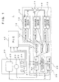
- Fig. 1 is a block diagram schematically illustrating the construction of an NC machine tool 1 according to the present invention.
- the NC machine tool 1 according to this embodiment has substantially the same construction as the aforesaid conventional NC machine tool 50, except that display control means 39 employing a display format different from the conventional one is provided instead of the display control means 33 of the NC machine tool 50, and that the axis selection signal and the multiplication factor selection signal outputted from the PLC 40 are inputted to the display control means 39 as well as the distribution means 32. Therefore, the same components as employed in the NC machine tool 50 are denoted by the same reference numerals, and no explanation will be given thereto.
- the display control means 39 employs a display format which includes a list display region 26 in which positional coordinates of the movable unit 11 with respect to the plurality of axes for movement (e.g., X-axis, Z-axis and C-axis) are displayed together with the designations of the axes in a list form, an enlarged display region 27 in which the designation of one of the axes selected by the axis selection switch 22 and a positional coordinate of the movable unit 11 with respect to the selected axis are displayed outside the list display region 26, and a multiplication factor display region 28 in which one of the multiplication factors selected by the multiplication factor selection switch 24 is displayed.
- a display format which includes a list display region 26 in which positional coordinates of the movable unit 11 with respect to the plurality of axes for movement (e.g., X-axis, Z-axis and C-axis) are displayed together with the designations of the axes in a list form, an enlarged display region 27 in
- the display control means 39 outputs positional coordinate data inputted from the positional coordinates calculating means 34 together with the display format data to the CRT 25, and displays the positional coordinate data in the list display region 26 on the CRT 25.
- the handle feed mode selection data and the multiplication factor data are inputted to the display control means 39 via the PLC 40.
- the display control means 39 outputs the positional coordinate data, the inputted axis selection data and multiplication factor data and the display format data to the CRT 25.
- the display control means 39 displays the positional coordinate data in the list display region 26, the axis selection data and the positional coordinate data on the selected axis in the enlarged display region 27, and the multiplication factor data in the multiplication factor display region 28 on the CRT 25.
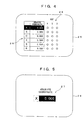
- a display image thus displayed on the CRT 25 is shown in Fig. 2. Areas for axes 4, 5 and 6 in the list display region 26 are spare areas.
- a reference numeral 29 denotes a reference point display region, in which reference points corresponding to origins on the respective axes (three points in this embodiment) are displayed and, when the movable unit 11 is located on an origin, a corresponding reference point is highlighted.
- the operator can easily recognize the positional coordinate data of the movable unit 11 on the selected axis in distinction from the positional coordinate data on the other axes and, therefore, readily and smoothly perform the moving operation.
- the multiplication factor data is displayed in the multiplication factor display region 28 specially provided, the way of displaying the multiplication factor data is not limited thereto.
- the multiplication factor data may be expressed in such a manner that the positional coordinate data on the selected axis displayed in the enlarged display region 27 has a reversely highlighted portion on a digit place thereof corresponding to the selected multiplication factor, as shown in Fig. 3.
- only the corresponding digit place may be shown in a different color, underlined, marked, or blinked. With this arrangement, the operator can easily recognize the selected multiplication factor.
- the positional coordinate data on the selected axis is displayed on a greater scale in the region provided separately from the list display region in which the positional coordinate data on the respective axes are displayed.
- the enlarged display is not necessarily required as long as the operator can easily recognize the positional coordinate data on the selected axis displayed in the separate region.
- the positional coordinate data on the selected axis may be displayed in a different display form, e.g., reversely highlighted or displayed in a different color as shown in Fig. 4, in the list display region 26 so as to be distinguished from the positional coordinate data on the other axes, although the positional coordinate data on the selected axis is displayed in the region separate from the list display region in the aforesaid embodiment.
- the digit place of the positional coordinate data corresponding to the multiplication factor may be marked as shown in Fig. 4, so that the operator can recognize the positional coordinate data on the selected axis as well as the multiplication factor data at a glance.
- the display control means 39 may be adapted to control the CRT 25, when the selection signal indicative of the axis selected by the axis selection switch 22 is inputted to the display control means 39 in the manual operation mode, as shown in Fig. 5 to display only the positional coordinate data on the selected axis instead of the list of the positional coordinate data on the respective axes as shown in FIG. 7. With this arrangement, the operator can more easily and accurately recognize the positional coordinate data on the selected axis to perform the moving operation of the movable unit 11 more efficiently.
Landscapes
- Engineering & Computer Science (AREA)
- Human Computer Interaction (AREA)
- Manufacturing & Machinery (AREA)
- Physics & Mathematics (AREA)
- General Physics & Mathematics (AREA)
- Automation & Control Theory (AREA)
- Numerical Control (AREA)
- Machine Tool Sensing Apparatuses (AREA)
Claims (5)
- NC-Werkzeugmaschine mit zumindest einer beweglichen Einheit (11), einer Antriebseinrichtung (12), die eine Vielzahl von Achsen zur Bewegung aufweist und betreibbar ist, die bewegliche Einheit (11) entlang den Achsen zu bewegen, einer manuellen Betätigungseinrichtung (23) zum Antrieb der Antriebseinrichtung (12) durch eine manuelle Betätigung, einer Achsenauswahleinrichtung (22) zur Auswahl einer Achse aus der Vielzahl der Achsen, entlang der die bewegliche Einheit (11) durch die manuelle Betätigungseinrichtung (23) zu bewegen ist, einer Positionskoordinatenberechnungseinrichtung (34) zur Berechnung von Positionskoordinaten der beweglichen Einheit (11) in Bezug auf die Vielzahl der Achsen auf der Grundlage einer Bewegungsanweisung, einer Anzeigeeinrichtung (25), die in der Lage ist, die Positionskoordinaten der beweglichen Einheit (11) in Bezug auf die Vielzahl der Achsen in zumindest einer Listenform anzuzeigen, und einer Anzeigesteuerungseinrichtung (25) zum Anzeigen der Positionskoordinaten zumindest in der Listenform auf der Anzeigeeinrichtung (25), wobei die NC-Werkzeugmaschine dadurch gekennzeichnet ist, dass die. Anzeigesteuerungseinrichtung (39) ein Auswahlsignal, das die ausgewählte Achse angibt, aus der Achsenauswahleinrichtung (22) in einer manuellen Betriebsart empfängt, und die Anzeigeeinrichtung (25) zur Anzeige einer Positionskoordinate der beweglichen Einheit (11) in Bezug auf die ausgewählte Achse in einer Anzeigeform steuert, die sich von einer Anzeigeform der Positionskoordinaten der beweglichen Einheit (11) in Bezug auf die anderen Achsen auf der Anzeigeeinrichtung (25) unterscheidet, wodurch die Positionskoordinate der beweglichen Einheit (11) in Bezug auf die ausgewählte Achse von den Positionskoordinaten in Bezug auf die anderen Achsen auf der Anzeigeeinrichtung (25) unterscheidbar ist.
- NC-Werkzeugmaschine nach Anspruch 1, wobei die Anzeigesteuerungseinrichtung (39) die Anzeigeeinrichtung (25) zum Anzeigen einer Liste der Positionskoordinaten der beweglichen Einheit (11) in Bezug auf die Vielzahl der Achsen und gleichzeitig zum Anzeigen der Positionskoordinate der beweglichen Einheit (11) in Bezug auf die ausgewählte Achse getrennt von der Liste der Positionskoordinaten auf der Anzeigeeinrichtung (11) in der manuellen Betriebsart steuert.
- NC-Werkzeugmaschine nach Anspruch 2, wobei die Anzeigesteuerungseinrichtung (39) die Anzeigeeinrichtung (25) zur Anzeige der Positionskoordinate in Bezug auf die ausgewählte Achse in einem größeren Maßstab getrennt von der Liste der Positionskoordinaten in Bezug auf die Vielzahl der Achsen auf der Anzeigeeinrichtung (25) in der manuellen Betriebsart steuert.
- NC-Werkzeugmaschine nach Anspruch 1, wobei die Anzeigesteuerungseinrichtung (39) die Anzeigeeinrichtung (25) zur Anzeige einer Liste der Positionskoordinaten in Bezug auf die Vielzahl der Achsen auf der Anzeigeeinrichtung (25) steuert, und in der manuellen Betriebsart lediglich die Positionskoordinate in Bezug auf die ausgewählte Achse auf der Anzeigeeinrichtung (25) anstelle der Liste der Positionskoordinaten in Bezug auf die Vielzahl der Achsen im Ansprechen auf den Empfang des Auswahlsignals aus der Achsenauswahleinrichtung (22) anzeigt.
- NC-Werkzeugmaschine nach einem der Ansprüche 1 bis 4,
wobei die manuelle Betätigungseinrichtung (23) eine Multiplikationsfaktorauswahleinrichtung (24) zum wahlweisen Ändern eines Multiplikationsfaktors aufweist, der das Verhältnis eines Bewegungsausmaßes der beweglichen Einheit (11) zu einem manuellen Betätigungsausmaß definiert,
wobei die Anzeigesteuerungseinrichtung (39) ein Auswahlsignal, das den ausgewählten Multiplikationsfaktor angibt, aus der Multiplikationsfaktorauswahleinrichtung (24) empfängt, und die Anzeigeeinrichtung (25) zur Anzeige der Positionskoordinaten der beweglichen Einheit (11) zusammen mit dem ausgewählten Multiplikationsfaktor auf der Anzeigeeinrichtung (25) steuert.
Applications Claiming Priority (2)
| Application Number | Priority Date | Filing Date | Title |
|---|---|---|---|
| JP10210522A JP2000042869A (ja) | 1998-07-27 | 1998-07-27 | Nc工作機械 |
| JP21052298 | 1998-07-27 |
Publications (2)
| Publication Number | Publication Date |
|---|---|
| EP0976494A1 EP0976494A1 (de) | 2000-02-02 |
| EP0976494B1 true EP0976494B1 (de) | 2003-10-01 |
Family
ID=16590769
Family Applications (1)
| Application Number | Title | Priority Date | Filing Date |
|---|---|---|---|
| EP99114611A Expired - Lifetime EP0976494B1 (de) | 1998-07-27 | 1999-07-26 | NC Werkzeugmaschine |
Country Status (4)
| Country | Link |
|---|---|
| US (1) | US6449528B1 (de) |
| EP (1) | EP0976494B1 (de) |
| JP (1) | JP2000042869A (de) |
| DE (1) | DE69911699T2 (de) |
Families Citing this family (4)
| Publication number | Priority date | Publication date | Assignee | Title |
|---|---|---|---|---|
| DE50004950D1 (de) | 2000-01-10 | 2004-02-05 | Siemens Ag | Universelle bewegungssteuerung |
| US6594541B1 (en) * | 2000-01-10 | 2003-07-15 | Siemens Aktiengesellschaft | Universal motion control |
| KR102184922B1 (ko) * | 2014-12-23 | 2020-12-01 | 두산공작기계 주식회사 | 공작 기계 |
| US10871763B2 (en) * | 2017-10-27 | 2020-12-22 | Dr. Johannes Heidenhain Gmbh | Manually operated machine tool display |
Family Cites Families (7)
| Publication number | Priority date | Publication date | Assignee | Title |
|---|---|---|---|---|
| DE2821843B1 (de) * | 1978-05-19 | 1979-10-18 | Heidenhain Gmbh Dr Johannes | Numerische Steuerung |
| GB2117284B (en) * | 1982-03-24 | 1985-12-11 | Gardner R F | Control of production equipment |
| US4648028A (en) * | 1984-08-31 | 1987-03-03 | General Electric Co. | Color enhanced display for a numerical control system |
| DE3775541D1 (de) * | 1987-02-05 | 1992-02-06 | Moog Gmbh | Vorrichtung zur steuerung der werkzeugstellung einer werkzeugmaschine. |
| JPH0242510A (ja) * | 1988-08-03 | 1990-02-13 | Fanuc Ltd | 加工情報表示方式 |
| GB2287386A (en) * | 1994-03-10 | 1995-09-13 | Ibm | Method of displaying text having improved useability |
| JPH10161717A (ja) | 1996-11-27 | 1998-06-19 | Okuma Mach Works Ltd | 数値データ表示機能を有する数値制御装置 |
-
1998
- 1998-07-27 JP JP10210522A patent/JP2000042869A/ja active Pending
-
1999
- 1999-07-23 US US09/359,749 patent/US6449528B1/en not_active Expired - Fee Related
- 1999-07-26 EP EP99114611A patent/EP0976494B1/de not_active Expired - Lifetime
- 1999-07-26 DE DE69911699T patent/DE69911699T2/de not_active Expired - Fee Related
Also Published As
| Publication number | Publication date |
|---|---|
| DE69911699D1 (de) | 2003-11-06 |
| DE69911699T2 (de) | 2004-08-19 |
| US6449528B1 (en) | 2002-09-10 |
| EP0976494A1 (de) | 2000-02-02 |
| JP2000042869A (ja) | 2000-02-15 |
Similar Documents
| Publication | Publication Date | Title |
|---|---|---|
| EP0780197B1 (de) | Vorrichtung und verfahren zum steuern der bewegung eines roboters | |
| EP2081096B1 (de) | Steuergerät für einen arbeitsteilfördernden Roboter | |
| EP1298509B1 (de) | Vorrichtung zur Vermeidung von Kollisionen bei numerisch gesteuerten Werkzeugmaschinen | |
| US5453674A (en) | Numerical control apparatus | |
| EP0116950B1 (de) | Numerisch gesteuertes Bearbeitungssystem | |
| EP0706852B1 (de) | Numerisch gesteuerte werkzeugmaschine | |
| US6449528B1 (en) | NC machine tool | |
| US6353301B1 (en) | Handle feeding control method in a numerical control apparatus, and a numerical control apparatus | |
| JP2017068525A (ja) | 数値制御装置と数値制御装置の制御方法 | |
| JPH0561525A (ja) | 移動体の動作表示装置及びその表示方法 | |
| US5808434A (en) | Numerical control apparatus | |
| US5920170A (en) | Numerical control apparatus and numerical control method | |
| WO2022190155A1 (ja) | ワーク加工装置 | |
| JP2559273B2 (ja) | 数値制御装置および数値制御装置の画面表示方法 | |
| EP0624833B1 (de) | Numerisches steuerungs-gerät und verfahren | |
| JPH05282047A (ja) | 手動送り運転処理装置 | |
| EP1632824A1 (de) | Numerische Steuerung mit Mitteln zum Ändern der Vorschubgeschwindigkeit | |
| JP3093095B2 (ja) | 操作形工作機械 | |
| JP3487713B2 (ja) | 早送り移動速度制御方法及びその装置 | |
| JP2802867B2 (ja) | 動作方向表示機能を備えた工作機械 | |
| EP0397884B1 (de) | Bearbeitungssystem für bahnkonturen | |
| EP0935179A1 (de) | Numerische steuerung mit lehr-/wiedergabefunktion | |
| CN121311324A (zh) | 机床的尾座及其设置方法 | |
| JP2963286B2 (ja) | 数値制御装置 | |
| JPH04131909A (ja) | 数値制御複合旋盤における加工座標系設定方法 |
Legal Events
| Date | Code | Title | Description |
|---|---|---|---|
| PUAI | Public reference made under article 153(3) epc to a published international application that has entered the european phase |
Free format text: ORIGINAL CODE: 0009012 |
|
| AK | Designated contracting states |
Kind code of ref document: A1 Designated state(s): DE FR GB IT |
|
| AX | Request for extension of the european patent |
Free format text: AL;LT;LV;MK;RO;SI |
|
| 17P | Request for examination filed |
Effective date: 20000508 |
|
| AKX | Designation fees paid |
Free format text: DE FR GB IT |
|
| GRAH | Despatch of communication of intention to grant a patent |
Free format text: ORIGINAL CODE: EPIDOS IGRA |
|
| GRAH | Despatch of communication of intention to grant a patent |
Free format text: ORIGINAL CODE: EPIDOS IGRA |
|
| GRAA | (expected) grant |
Free format text: ORIGINAL CODE: 0009210 |
|
| AK | Designated contracting states |
Kind code of ref document: B1 Designated state(s): DE FR GB IT |
|
| REG | Reference to a national code |
Ref country code: GB Ref legal event code: FG4D |
|
| REF | Corresponds to: |
Ref document number: 69911699 Country of ref document: DE Date of ref document: 20031106 Kind code of ref document: P |
|
| ET | Fr: translation filed | ||
| PG25 | Lapsed in a contracting state [announced via postgrant information from national office to epo] |
Ref country code: GB Free format text: LAPSE BECAUSE OF NON-PAYMENT OF DUE FEES Effective date: 20040726 |
|
| PLBE | No opposition filed within time limit |
Free format text: ORIGINAL CODE: 0009261 |
|
| STAA | Information on the status of an ep patent application or granted ep patent |
Free format text: STATUS: NO OPPOSITION FILED WITHIN TIME LIMIT |
|
| 26N | No opposition filed |
Effective date: 20040702 |
|
| GBPC | Gb: european patent ceased through non-payment of renewal fee |
Effective date: 20040726 |
|
| PG25 | Lapsed in a contracting state [announced via postgrant information from national office to epo] |
Ref country code: FR Free format text: LAPSE BECAUSE OF NON-PAYMENT OF DUE FEES Effective date: 20050331 |
|
| REG | Reference to a national code |
Ref country code: FR Ref legal event code: ST |
|
| PG25 | Lapsed in a contracting state [announced via postgrant information from national office to epo] |
Ref country code: IT Free format text: LAPSE BECAUSE OF NON-PAYMENT OF DUE FEES Effective date: 20050726 |
|
| PGFP | Annual fee paid to national office [announced via postgrant information from national office to epo] |
Ref country code: DE Payment date: 20080731 Year of fee payment: 10 |
|
| PG25 | Lapsed in a contracting state [announced via postgrant information from national office to epo] |
Ref country code: DE Free format text: LAPSE BECAUSE OF NON-PAYMENT OF DUE FEES Effective date: 20100202 |