EP0976502A2 - Retaining device of socket spanner - Google Patents
Retaining device of socket spanner Download PDFInfo
- Publication number
- EP0976502A2 EP0976502A2 EP99108694A EP99108694A EP0976502A2 EP 0976502 A2 EP0976502 A2 EP 0976502A2 EP 99108694 A EP99108694 A EP 99108694A EP 99108694 A EP99108694 A EP 99108694A EP 0976502 A2 EP0976502 A2 EP 0976502A2
- Authority
- EP
- European Patent Office
- Prior art keywords
- socket
- elastic body
- fitting end
- present
- spanner
- Prior art date
- Legal status (The legal status is an assumption and is not a legal conclusion. Google has not performed a legal analysis and makes no representation as to the accuracy of the status listed.)
- Granted
Links
- 230000000717 retained effect Effects 0.000 claims abstract description 6
- 238000010276 construction Methods 0.000 claims description 4
- 230000007812 deficiency Effects 0.000 description 1
- 230000000694 effects Effects 0.000 description 1
- 238000005242 forging Methods 0.000 description 1
- 238000000034 method Methods 0.000 description 1
Images



Classifications
-
- B—PERFORMING OPERATIONS; TRANSPORTING
- B25—HAND TOOLS; PORTABLE POWER-DRIVEN TOOLS; MANIPULATORS
- B25B—TOOLS OR BENCH DEVICES NOT OTHERWISE PROVIDED FOR, FOR FASTENING, CONNECTING, DISENGAGING OR HOLDING
- B25B13/00—Spanners; Wrenches
- B25B13/02—Spanners; Wrenches with rigid jaws
- B25B13/06—Spanners; Wrenches with rigid jaws of socket type
-
- B—PERFORMING OPERATIONS; TRANSPORTING
- B25—HAND TOOLS; PORTABLE POWER-DRIVEN TOOLS; MANIPULATORS
- B25B—TOOLS OR BENCH DEVICES NOT OTHERWISE PROVIDED FOR, FOR FASTENING, CONNECTING, DISENGAGING OR HOLDING
- B25B23/00—Details of, or accessories for, spanners, wrenches, screwdrivers
- B25B23/02—Arrangements for handling screws or nuts
- B25B23/08—Arrangements for handling screws or nuts for holding or positioning screw or nut prior to or during its rotation
- B25B23/10—Arrangements for handling screws or nuts for holding or positioning screw or nut prior to or during its rotation using mechanical gripping means
- B25B23/105—Arrangements for handling screws or nuts for holding or positioning screw or nut prior to or during its rotation using mechanical gripping means the gripping device being an integral part of the driving bit
- B25B23/108—Arrangements for handling screws or nuts for holding or positioning screw or nut prior to or during its rotation using mechanical gripping means the gripping device being an integral part of the driving bit the driving bit being a Philips type bit, an Allen type bit or a socket
Definitions
- the present invention relates generally to a socket spanner, and mote particularly to a retaining device of the socket spanner.
- the U.S. Patent Serial NO.08/672,859 filed by this inventor of the present invention discloses a socket 20 having a fitting end 22 which is provided in the inner wall thereof with two grooves 221 corresponding in location to each other.
- the fitting end 22 is further provided in proximity of one end thereof with a circular slot 222.
- An elastic wire 24 is fined into the fitting end 22 of the socket 20 such that a retaining side 241 of the elastic wire 24 is retained in the grooves 221 of the fitting end 22, and that an end portion 244 of the elastic wire 24 urges the circular slot 222 of the fining end 22.
- a protruded edge 242 of the retaining side 241 of the elastic wire 24 is capable of retaining a nut which is engaged with the fitting end 22 of the socket 20.
- the retaining side 241 is capable of preventing the elastic wire 24 from slipping out of the socket 20 at the time when the nut is taken out of the socket 20.
- the structural integrity of the socket 20 can be undermined by the grooves 221 in the process of making the socket 20 by forging.
- the primary objective of the present invention is therefore to provided a socket spanner with a retaining means free from the structural deficiency of the prior art described above.
- the foregoing objective of the present invention is attained by a socket which is in turn provided in one of six sides thereof with a receiving portion.
- the fitting end of the socket is provided with an elastic wire fitted thereinto such that a retaining side of the elastic wire is retained in the receiving portion of the hexagonal hole, thereby bringing about the retaining effect of the socket.
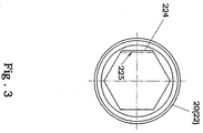
- a socket spanner 20 of a first preferred embodiment of the present invention is provided with a fitting end 22 having a hexagonal hole.
- One of the six inner side walls 224 of the hexagonal hole of the fining end 22 is provided with a receiving portion 225.
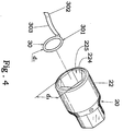
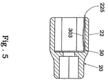
- the fining end 22 of the socket spanner 20 of the present invention is provided with an elastic body 30 which is composed of a press ring 301 and a retaining side 302 extending from the press ring 301 and having a protruded edge 303.
- the press ring 301 has an outer diameter, d1, which is slightly greater than an inner diameter, d2, of the hexagonal hole of the fitting end 22.
- the elastic body 30 is forced into the fining end 22 by pressing such that the retaining side 302 of the elastic body 30 is retained in the receiving portion 225 of the hexagonal hole of the fitting end 22.
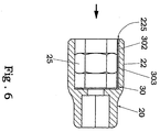
- a nut 25 is retained in the fining end 22 of the socket spanner 20 such that the nut 25 is urged and held securely by the protruded edge 303 of the elastic body 30. As illustrated in FIG. 1, the nut 25 can be taken out of the fining end 22 without causing the elastic body 30 to become disengaged with the fitting end 22.
- the socket spanner 20 of the present invention may be modified in such a way that the elastic body 30 is composed of a semicircular press ring 301 and the retaining side 302.
- the working mechanism of the second preferred embodiment of the present invention is identical with that of the first preferred embodiment of the present invention. It must be noted here that the press portion 301 of the elastic body 30 of the first preferred embodiment of the present invention is of a closed ring construction, and that the press portion 301 of the elastic body 30 of the second preferred embodiment of the present invention is of a semicircular construction.
Landscapes
- Mechanical Engineering (AREA)
- Engineering & Computer Science (AREA)
- Details Of Spanners, Wrenches, And Screw Drivers And Accessories (AREA)
- Analysing Materials By The Use Of Radiation (AREA)
- Snaps, Bayonet Connections, Set Pins, And Snap Rings (AREA)
- Apparatus For Radiation Diagnosis (AREA)
- Processing Of Terminals (AREA)
- Magnetic Heads (AREA)
- Manipulator (AREA)
- Gasket Seals (AREA)
- Installation Of Indoor Wiring (AREA)
- Knitting Machines (AREA)
- Yarns And Mechanical Finishing Of Yarns Or Ropes (AREA)
- Treatment Of Fiber Materials (AREA)
- Joints With Sleeves (AREA)
Abstract
Description
- The present invention relates generally to a socket spanner, and mote particularly to a retaining device of the socket spanner.
- As shown in FIG.1, the U.S. Patent Serial NO.08/672,859 filed by this inventor of the present invention discloses a
socket 20 having afitting end 22 which is provided in the inner wall thereof with twogrooves 221 corresponding in location to each other. Thefitting end 22 is further provided in proximity of one end thereof with acircular slot 222. Anelastic wire 24 is fined into thefitting end 22 of thesocket 20 such that aretaining side 241 of theelastic wire 24 is retained in thegrooves 221 of thefitting end 22, and that anend portion 244 of theelastic wire 24 urges thecircular slot 222 of thefining end 22. As a result, aprotruded edge 242 of the retainingside 241 of theelastic wire 24 is capable of retaining a nut which is engaged with thefitting end 22 of thesocket 20. In the meantime, theretaining side 241 is capable of preventing theelastic wire 24 from slipping out of thesocket 20 at the time when the nut is taken out of thesocket 20. As shown in FIG.2,the structural integrity of thesocket 20 can be undermined by thegrooves 221 in the process of making thesocket 20 by forging. - The primary objective of the present invention is therefore to provided a socket spanner with a retaining means free from the structural deficiency of the prior art described above.
- In keeping with the principle of the present invention, the foregoing objective of the present invention is attained by a socket which is in turn provided in one of six sides thereof with a receiving portion. The fitting end of the socket is provided with an elastic wire fitted thereinto such that a retaining side of the elastic wire is retained in the receiving portion of the hexagonal hole, thereby bringing about the retaining effect of the socket.
- The foregoing objective, features, function, and advantages of the present invention will be more readily understood upon a thoughtful deliberation of the following detailed description of the present invention with reference to the accompanying drawings.
-
- FIG. 1
- shows an exploded view of the prior art.
- FIG.2
- shows a schematic view of a fining end of a socket spanner of the prior art.
- FIG.3
- shows a schematic view of a fitting end of a socket spanner of the present invention.
- FIG.4
- shows an exploded view of the fining end of the socket spanner of the present invention.
- FIG.5
- shows a sectional schematic view of the present invention.
- FIG.6
- shows a schematic view of the present invention at work.
- FIG.7
- shows another schematic view of the present invention at work.
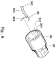
- FIG.8
- show an exploded view of another preferred embodiment of the present invention.
- As shown in FIH.3, a
socket spanner 20 of a first preferred embodiment of the present invention is provided with afitting end 22 having a hexagonal hole. One of the sixinner side walls 224 of the hexagonal hole of thefining end 22 is provided with a receivingportion 225. - As shown in FIGS.4 and 5, the
fining end 22 of thesocket spanner 20 of the present invention is provided with anelastic body 30 which is composed of apress ring 301 and aretaining side 302 extending from thepress ring 301 and having aprotruded edge 303. Thepress ring 301 has an outer diameter, d1, which is slightly greater than an inner diameter, d2, of the hexagonal hole of thefitting end 22. In combination, theelastic body 30 is forced into thefining end 22 by pressing such that the retainingside 302 of theelastic body 30 is retained in thereceiving portion 225 of the hexagonal hole of thefitting end 22. - As illustrated in FIG.6, a
nut 25 is retained in thefining end 22 of thesocket spanner 20 such that thenut 25 is urged and held securely by theprotruded edge 303 of theelastic body 30. As illustrated in FIG. 1, thenut 25 can be taken out of thefining end 22 without causing theelastic body 30 to become disengaged with thefitting end 22. - As shown in FIG.8, the
socket spanner 20 of the present invention may be modified in such a way that theelastic body 30 is composed of asemicircular press ring 301 and the retainingside 302. The working mechanism of the second preferred embodiment of the present invention is identical with that of the first preferred embodiment of the present invention. It must be noted here that thepress portion 301 of theelastic body 30 of the first preferred embodiment of the present invention is of a closed ring construction, and that thepress portion 301 of theelastic body 30 of the second preferred embodiment of the present invention is of a semicircular construction. - The embodiments of the present invention described above are to be deemed in all respects as being merely illustrative and not restrictive. Accordingly, the present invention may be embodied in other specific forms without deviating from the spirit thereof. The present invention is therefore to be limited only by the scopes of the following appended claims.
Claims (4)
- A socket spanner provided with a retaining device consisting of a socket and an elastic body; wherein said socket has a fitting end with a hexagonal hole which is provided in one of six inner side walls thereof with a receiving portion; and wherein said elastic body is composed of a press portion and a retaining side extending from said press portion and having a protruded edge, said elastic body being fitted securely into said fining end of said socket such that said retaining side of said elastic body is retained in said receiving portion of said hexagonal hole of said fitting end so as to prevent said elastic body from slipping out of said fitting end of said socket, and that said protruded edge of said retaining side of said elastic body is capable of holding securely a nut which is engaged with said fitting end of said socket.
- The socket spanner as defined in claim 1,wherein said press portion of said elastic body is of a closed ring construction.
- The socket spanner as defined in claim 1,wherein said press portion of said elastic body is of a semicircular construction.
- The socket spanner as defined in claim 2,wherein said press portion of said elastic body has an outer diameter greater than an inner diameter of said hexagonal hole of said fitting end of said socket.
Applications Claiming Priority (3)
| Application Number | Priority Date | Filing Date | Title |
|---|---|---|---|
| US09/122,594 US6082229A (en) | 1998-07-25 | 1998-07-25 | Retaining device of socket spanner |
| DE29813496U | 1998-07-29 | ||
| DE29813496U DE29813496U1 (en) | 1998-07-25 | 1998-07-29 | Clamping sleeve |
Publications (3)
| Publication Number | Publication Date |
|---|---|
| EP0976502A2 true EP0976502A2 (en) | 2000-02-02 |
| EP0976502A3 EP0976502A3 (en) | 2000-05-10 |
| EP0976502B1 EP0976502B1 (en) | 2002-07-31 |
Family
ID=26061703
Family Applications (1)
| Application Number | Title | Priority Date | Filing Date |
|---|---|---|---|
| EP99108694A Expired - Lifetime EP0976502B1 (en) | 1998-07-25 | 1999-05-18 | Retaining device of socket spanner |
Country Status (7)
| Country | Link |
|---|---|
| US (1) | US6082229A (en) |
| EP (1) | EP0976502B1 (en) |
| CN (1) | CN2369821Y (en) |
| AT (1) | ATE221433T1 (en) |
| DE (2) | DE29813496U1 (en) |
| DK (1) | DK0976502T3 (en) |
| ES (1) | ES2181333T3 (en) |
Cited By (2)
| Publication number | Priority date | Publication date | Assignee | Title |
|---|---|---|---|---|
| US10576611B2 (en) | 2016-07-26 | 2020-03-03 | Milwaukee Electric Tool Corporation | Ratchet, ratchet accessory, and kit including the same |
| US12097595B2 (en) | 2016-07-26 | 2024-09-24 | Milwaukee Electric Tool Corporation | Ratchet, ratchet accessory, and kit including the same |
Families Citing this family (17)
| Publication number | Priority date | Publication date | Assignee | Title |
|---|---|---|---|---|
| DE20209895U1 (en) * | 2002-06-21 | 2002-10-02 | Adolf Würth GmbH & Co. KG, 74653 Künzelsau | wrench |
| TWM268148U (en) * | 2004-12-09 | 2005-06-21 | Mobiletron Electronics Co Ltd | Adaptor socket for pneumatic/electric pounding and rotating tool |
| US7299721B1 (en) * | 2006-07-24 | 2007-11-27 | Snap-On Incororated | Socket including a reinforcing structure |
| US20100294087A1 (en) * | 2009-05-20 | 2010-11-25 | Gong Fong Enterprise Co., Ltd. | Tool sleeve clamping structure |
| CN102485434B (en) * | 2010-12-01 | 2014-07-02 | 鸿安国际兴业有限公司 | Magnetic attracting device installed at square hole of sleeve barrel |
| US8939050B2 (en) * | 2013-02-28 | 2015-01-27 | Yi-Fu Chen | Driving head with an elastic buckle |
| USD814259S1 (en) | 2016-08-17 | 2018-04-03 | Milwaukee Electric Tool Corporation | Socket |
| USD815504S1 (en) | 2016-08-17 | 2018-04-17 | Milwaukee Electric Tool Corporation | Socket |
| USD810531S1 (en) | 2016-08-29 | 2018-02-20 | Milwaukee Electric Tool Corporation | Socket |
| CN109129276A (en) * | 2017-06-15 | 2019-01-04 | 卓耀霖 | sleeve engaging device |
| US11554470B2 (en) | 2017-12-13 | 2023-01-17 | Apex Brands, Inc. | Extractor socket with bidirectional driving capability and corresponding extraction set with intermediate sizes |
| JP7110627B2 (en) * | 2018-03-06 | 2022-08-02 | トヨタ自動車株式会社 | fastening tool |
| USD971705S1 (en) * | 2020-03-09 | 2022-12-06 | Apex Brands, Inc. | Socket |
| USD950332S1 (en) * | 2020-10-26 | 2022-05-03 | Act Quality Industrial Co., Ltd. | Socket |
| USD1024708S1 (en) * | 2021-04-22 | 2024-04-30 | Kabo Tool Company | Lightweight socket structure |
| JP1715612S (en) * | 2021-06-15 | 2022-05-23 | Wrench socket | |
| USD1081313S1 (en) | 2022-09-22 | 2025-07-01 | Apex Brands, Inc. | Extractor insert |
Family Cites Families (11)
| Publication number | Priority date | Publication date | Assignee | Title |
|---|---|---|---|---|
| US3665791A (en) * | 1971-01-21 | 1972-05-30 | Harry A Carr | Keeper for hexagonal fastener wrenches |
| US3835737A (en) * | 1971-10-08 | 1974-09-17 | H Carr | Keeper for socket wrenches |
| US3834253A (en) * | 1972-06-08 | 1974-09-10 | H Carr | Keeper for socket wrenches |
| US4607547A (en) * | 1985-02-06 | 1986-08-26 | Martus Donald G | Stripped hex head drive socket |
| US4644831A (en) * | 1985-07-05 | 1987-02-24 | Miriam Yang | Adaptor sleeve |
| US4787278A (en) * | 1988-03-30 | 1988-11-29 | Western Pacific Industries Inc. | Tool bit driver with spring retainer |
| US5042333A (en) * | 1991-03-04 | 1991-08-27 | Daniel Huang | Adapter sleeve |
| US5724872A (en) * | 1996-06-28 | 1998-03-10 | Shih; Leo | Socket spanner having a nut retaining device |
| US6178854B1 (en) * | 1998-07-25 | 2001-01-30 | Leo Shih | Socket spanner provided with retaining device |
| DE29907298U1 (en) * | 1999-04-26 | 1999-07-29 | Shih, Leo, Taichung | Clamping sleeve |
| DE29907299U1 (en) * | 1999-04-26 | 1999-07-29 | Shih, Leo, Taichung | Clamping sleeve |
-
1998
- 1998-07-25 US US09/122,594 patent/US6082229A/en not_active Expired - Lifetime
- 1998-07-29 DE DE29813496U patent/DE29813496U1/en not_active Expired - Lifetime
-
1999
- 1999-04-07 CN CN99208701U patent/CN2369821Y/en not_active Expired - Lifetime
- 1999-05-18 EP EP99108694A patent/EP0976502B1/en not_active Expired - Lifetime
- 1999-05-18 ES ES99108694T patent/ES2181333T3/en not_active Expired - Lifetime
- 1999-05-18 DK DK99108694T patent/DK0976502T3/en active
- 1999-05-18 DE DE69902325T patent/DE69902325T2/en not_active Expired - Fee Related
- 1999-05-18 AT AT99108694T patent/ATE221433T1/en not_active IP Right Cessation
Cited By (4)
| Publication number | Priority date | Publication date | Assignee | Title |
|---|---|---|---|---|
| US10576611B2 (en) | 2016-07-26 | 2020-03-03 | Milwaukee Electric Tool Corporation | Ratchet, ratchet accessory, and kit including the same |
| US10688630B2 (en) | 2016-07-26 | 2020-06-23 | Milwaukee Electric Tool Corporation | Ratchet, ratchet accessory, and kit including the same |
| US11534895B2 (en) | 2016-07-26 | 2022-12-27 | Milwaukee Electric Tool Corporation | Ratchet, ratchet accessory, and kit including the same |
| US12097595B2 (en) | 2016-07-26 | 2024-09-24 | Milwaukee Electric Tool Corporation | Ratchet, ratchet accessory, and kit including the same |
Also Published As
| Publication number | Publication date |
|---|---|
| DK0976502T3 (en) | 2002-11-04 |
| ES2181333T3 (en) | 2003-02-16 |
| EP0976502B1 (en) | 2002-07-31 |
| DE29813496U1 (en) | 1998-11-05 |
| US6082229A (en) | 2000-07-04 |
| DE69902325T2 (en) | 2003-06-18 |
| EP0976502A3 (en) | 2000-05-10 |
| DE69902325D1 (en) | 2002-09-05 |
| CN2369821Y (en) | 2000-03-22 |
| ATE221433T1 (en) | 2002-08-15 |
Similar Documents
| Publication | Publication Date | Title |
|---|---|---|
| EP0976502A2 (en) | Retaining device of socket spanner | |
| US6543959B1 (en) | Two-way quick connector | |
| US4991468A (en) | Barrel type sockets | |
| US4096896A (en) | Composite tool structure | |
| US6178854B1 (en) | Socket spanner provided with retaining device | |
| US5520075A (en) | Socket wrench set and fastener | |
| US5568757A (en) | Socket wrench adapter | |
| US6481315B1 (en) | Box and ratchet wheel arrangement for wrench | |
| US6357323B2 (en) | Wrench | |
| US4644831A (en) | Adaptor sleeve | |
| US20030126960A1 (en) | Socket device having an improved driving structure | |
| US6945142B1 (en) | Socket | |
| US4054067A (en) | Compact screwdriver bit | |
| US6550357B1 (en) | Wrench connector | |
| US4934221A (en) | Apparatus for retaining a replaceable tool head on a T-handle-type wrench | |
| US20020178874A1 (en) | Intermediate member for connecting with tools | |
| US6460431B1 (en) | Ratchet tool | |
| US6698320B2 (en) | Retainer ring for securely retaining a first object to a second object | |
| JPH07164341A (en) | Tubular spanner with clamp retaining means | |
| EP0771251B1 (en) | A pair of pliers | |
| US6966243B1 (en) | Universal plier structure | |
| US20020178872A1 (en) | Varying sized thru socket attachement system with hand wrench | |
| US20060000316A1 (en) | Wrench with socket engaged by coupling shaft protruded from wrench body | |
| US20040226415A1 (en) | Apparatus for firmly connecting wrench with socket | |
| US6327939B1 (en) | Wrench orifice with lateral gripping grooves |
Legal Events
| Date | Code | Title | Description |
|---|---|---|---|
| PUAI | Public reference made under article 153(3) epc to a published international application that has entered the european phase |
Free format text: ORIGINAL CODE: 0009012 |
|
| AK | Designated contracting states |
Kind code of ref document: A2 Designated state(s): AT BE CH DE DK ES FR GB IT LI NL SE |
|
| AX | Request for extension of the european patent |
Free format text: AL;LT;LV;MK;RO;SI |
|
| PUAL | Search report despatched |
Free format text: ORIGINAL CODE: 0009013 |
|
| AK | Designated contracting states |
Kind code of ref document: A3 Designated state(s): AT BE CH CY DE DK ES FI FR GB GR IE IT LI LU MC NL PT SE |
|
| AX | Request for extension of the european patent |
Free format text: AL;LT;LV;MK;RO;SI |
|
| 17P | Request for examination filed |
Effective date: 20000525 |
|
| AKX | Designation fees paid |
Free format text: AT BE CH DE DK ES FR GB IT LI NL SE |
|
| 17Q | First examination report despatched |
Effective date: 20010308 |
|
| GRAG | Despatch of communication of intention to grant |
Free format text: ORIGINAL CODE: EPIDOS AGRA |
|
| RAP1 | Party data changed (applicant data changed or rights of an application transferred) |
Owner name: SHIH, LEO |
|
| RIN1 | Information on inventor provided before grant (corrected) |
Inventor name: SHIH, LEO |
|
| GRAG | Despatch of communication of intention to grant |
Free format text: ORIGINAL CODE: EPIDOS AGRA |
|
| GRAH | Despatch of communication of intention to grant a patent |
Free format text: ORIGINAL CODE: EPIDOS IGRA |
|
| GRAH | Despatch of communication of intention to grant a patent |
Free format text: ORIGINAL CODE: EPIDOS IGRA |
|
| GRAA | (expected) grant |
Free format text: ORIGINAL CODE: 0009210 |
|
| AK | Designated contracting states |
Kind code of ref document: B1 Designated state(s): AT BE CH DE DK ES FR GB IT LI NL SE |
|
| REF | Corresponds to: |
Ref document number: 221433 Country of ref document: AT Date of ref document: 20020815 Kind code of ref document: T |
|
| REG | Reference to a national code |
Ref country code: GB Ref legal event code: FG4D Ref country code: CH Ref legal event code: EP |
|
| REF | Corresponds to: |
Ref document number: 69902325 Country of ref document: DE Date of ref document: 20020905 |
|
| REG | Reference to a national code |
Ref country code: CH Ref legal event code: NV Representative=s name: BUECHEL, KAMINSKI & PARTNER PATENTANWAELTE ESTABLI |
|
| ET | Fr: translation filed | ||
| REG | Reference to a national code |
Ref country code: ES Ref legal event code: FG2A Ref document number: 2181333 Country of ref document: ES Kind code of ref document: T3 |
|
| PGFP | Annual fee paid to national office [announced via postgrant information from national office to epo] |
Ref country code: AT Payment date: 20030514 Year of fee payment: 5 |
|
| PGFP | Annual fee paid to national office [announced via postgrant information from national office to epo] |
Ref country code: DK Payment date: 20030520 Year of fee payment: 5 |
|
| PGFP | Annual fee paid to national office [announced via postgrant information from national office to epo] |
Ref country code: ES Payment date: 20030529 Year of fee payment: 5 |
|
| PGFP | Annual fee paid to national office [announced via postgrant information from national office to epo] |
Ref country code: NL Payment date: 20030530 Year of fee payment: 5 |
|
| PGFP | Annual fee paid to national office [announced via postgrant information from national office to epo] |
Ref country code: CH Payment date: 20030531 Year of fee payment: 5 |
|
| PLBE | No opposition filed within time limit |
Free format text: ORIGINAL CODE: 0009261 |
|
| STAA | Information on the status of an ep patent application or granted ep patent |
Free format text: STATUS: NO OPPOSITION FILED WITHIN TIME LIMIT |
|
| PGFP | Annual fee paid to national office [announced via postgrant information from national office to epo] |
Ref country code: BE Payment date: 20030716 Year of fee payment: 5 |
|
| 26N | No opposition filed |
Effective date: 20030506 |
|
| PG25 | Lapsed in a contracting state [announced via postgrant information from national office to epo] |
Ref country code: AT Free format text: LAPSE BECAUSE OF NON-PAYMENT OF DUE FEES Effective date: 20040518 |
|
| PG25 | Lapsed in a contracting state [announced via postgrant information from national office to epo] |
Ref country code: ES Free format text: LAPSE BECAUSE OF NON-PAYMENT OF DUE FEES Effective date: 20040519 |
|
| PG25 | Lapsed in a contracting state [announced via postgrant information from national office to epo] |
Ref country code: LI Free format text: LAPSE BECAUSE OF NON-PAYMENT OF DUE FEES Effective date: 20040531 Ref country code: CH Free format text: LAPSE BECAUSE OF NON-PAYMENT OF DUE FEES Effective date: 20040531 Ref country code: BE Free format text: LAPSE BECAUSE OF NON-PAYMENT OF DUE FEES Effective date: 20040531 |
|
| PG25 | Lapsed in a contracting state [announced via postgrant information from national office to epo] |
Ref country code: DK Free format text: LAPSE BECAUSE OF NON-PAYMENT OF DUE FEES Effective date: 20040601 |
|
| BERE | Be: lapsed |
Owner name: *SHIH LEO Effective date: 20040531 |
|
| PG25 | Lapsed in a contracting state [announced via postgrant information from national office to epo] |
Ref country code: NL Free format text: LAPSE BECAUSE OF NON-PAYMENT OF DUE FEES Effective date: 20041201 |
|
| REG | Reference to a national code |
Ref country code: DK Ref legal event code: EBP |
|
| REG | Reference to a national code |
Ref country code: CH Ref legal event code: PL |
|
| NLV4 | Nl: lapsed or anulled due to non-payment of the annual fee |
Effective date: 20041201 |
|
| PGFP | Annual fee paid to national office [announced via postgrant information from national office to epo] |
Ref country code: SE Payment date: 20050506 Year of fee payment: 7 |
|
| PG25 | Lapsed in a contracting state [announced via postgrant information from national office to epo] |
Ref country code: IT Free format text: LAPSE BECAUSE OF NON-PAYMENT OF DUE FEES Effective date: 20050518 |
|
| REG | Reference to a national code |
Ref country code: ES Ref legal event code: FD2A Effective date: 20040519 |
|
| PG25 | Lapsed in a contracting state [announced via postgrant information from national office to epo] |
Ref country code: SE Free format text: LAPSE BECAUSE OF NON-PAYMENT OF DUE FEES Effective date: 20060519 |
|
| EUG | Se: european patent has lapsed | ||
| PGFP | Annual fee paid to national office [announced via postgrant information from national office to epo] |
Ref country code: DE Payment date: 20080522 Year of fee payment: 10 |
|
| PGFP | Annual fee paid to national office [announced via postgrant information from national office to epo] |
Ref country code: GB Payment date: 20080521 Year of fee payment: 10 |
|
| GBPC | Gb: european patent ceased through non-payment of renewal fee |
Effective date: 20090518 |
|
| REG | Reference to a national code |
Ref country code: FR Ref legal event code: ST Effective date: 20100129 |
|
| PG25 | Lapsed in a contracting state [announced via postgrant information from national office to epo] |
Ref country code: FR Free format text: LAPSE BECAUSE OF NON-PAYMENT OF DUE FEES Effective date: 20090602 |
|
| PGFP | Annual fee paid to national office [announced via postgrant information from national office to epo] |
Ref country code: FR Payment date: 20080514 Year of fee payment: 10 |
|
| PG25 | Lapsed in a contracting state [announced via postgrant information from national office to epo] |
Ref country code: GB Free format text: LAPSE BECAUSE OF NON-PAYMENT OF DUE FEES Effective date: 20090518 |
|
| PG25 | Lapsed in a contracting state [announced via postgrant information from national office to epo] |
Ref country code: DE Free format text: LAPSE BECAUSE OF NON-PAYMENT OF DUE FEES Effective date: 20091201 |