EP0976609B1 - Table pliante à attacher à la face arrière d'un dossier d'un siège de passager dans un omnibus ou un avion - Google Patents
Table pliante à attacher à la face arrière d'un dossier d'un siège de passager dans un omnibus ou un avion Download PDFInfo
- Publication number
- EP0976609B1 EP0976609B1 EP99113129A EP99113129A EP0976609B1 EP 0976609 B1 EP0976609 B1 EP 0976609B1 EP 99113129 A EP99113129 A EP 99113129A EP 99113129 A EP99113129 A EP 99113129A EP 0976609 B1 EP0976609 B1 EP 0976609B1
- Authority
- EP
- European Patent Office
- Prior art keywords
- folding table
- holder
- use position
- backrest
- folding
- Prior art date
- Legal status (The legal status is an assumption and is not a legal conclusion. Google has not performed a legal analysis and makes no representation as to the accuracy of the status listed.)
- Expired - Lifetime
Links
- 235000013361 beverage Nutrition 0.000 claims description 30
- 239000011521 glass Substances 0.000 abstract description 2
- 230000000295 complement effect Effects 0.000 description 4
- 210000002414 leg Anatomy 0.000 description 4
- 238000013016 damping Methods 0.000 description 3
- 230000005484 gravity Effects 0.000 description 3
- 230000001788 irregular Effects 0.000 description 3
- 208000027418 Wounds and injury Diseases 0.000 description 2
- 230000006378 damage Effects 0.000 description 2
- 208000014674 injury Diseases 0.000 description 2
- 210000003127 knee Anatomy 0.000 description 2
- 239000011324 bead Substances 0.000 description 1
- 230000000881 depressing effect Effects 0.000 description 1
- 238000002347 injection Methods 0.000 description 1
- 239000007924 injection Substances 0.000 description 1
- 238000003780 insertion Methods 0.000 description 1
- 230000037431 insertion Effects 0.000 description 1
- 239000007788 liquid Substances 0.000 description 1
Images




Classifications
-
- B—PERFORMING OPERATIONS; TRANSPORTING
- B60—VEHICLES IN GENERAL
- B60N—SEATS SPECIALLY ADAPTED FOR VEHICLES; VEHICLE PASSENGER ACCOMMODATION NOT OTHERWISE PROVIDED FOR
- B60N3/00—Arrangements or adaptations of other passenger fittings, not otherwise provided for
-
- B—PERFORMING OPERATIONS; TRANSPORTING
- B60—VEHICLES IN GENERAL
- B60N—SEATS SPECIALLY ADAPTED FOR VEHICLES; VEHICLE PASSENGER ACCOMMODATION NOT OTHERWISE PROVIDED FOR
- B60N3/00—Arrangements or adaptations of other passenger fittings, not otherwise provided for
- B60N3/10—Arrangements or adaptations of other passenger fittings, not otherwise provided for of receptacles for food or beverages, e.g. refrigerated
- B60N3/102—Arrangements or adaptations of other passenger fittings, not otherwise provided for of receptacles for food or beverages, e.g. refrigerated storable or foldable in a non-use position
-
- B—PERFORMING OPERATIONS; TRANSPORTING
- B60—VEHICLES IN GENERAL
- B60N—SEATS SPECIALLY ADAPTED FOR VEHICLES; VEHICLE PASSENGER ACCOMMODATION NOT OTHERWISE PROVIDED FOR
- B60N3/00—Arrangements or adaptations of other passenger fittings, not otherwise provided for
- B60N3/001—Arrangements or adaptations of other passenger fittings, not otherwise provided for of tables or trays
- B60N3/002—Arrangements or adaptations of other passenger fittings, not otherwise provided for of tables or trays of trays
- B60N3/004—Arrangements or adaptations of other passenger fittings, not otherwise provided for of tables or trays of trays of foldable trays mounted on the back-rest
-
- B—PERFORMING OPERATIONS; TRANSPORTING
- B64—AIRCRAFT; AVIATION; COSMONAUTICS
- B64D—EQUIPMENT FOR FITTING IN OR TO AIRCRAFT; FLIGHT SUITS; PARACHUTES; ARRANGEMENT OR MOUNTING OF POWER PLANTS OR PROPULSION TRANSMISSIONS IN AIRCRAFT
- B64D11/00—Passenger or crew accommodation; Flight-deck installations not otherwise provided for
- B64D11/06—Arrangements of seats, or adaptations or details specially adapted for aircraft seats
- B64D11/0638—Arrangements of seats, or adaptations or details specially adapted for aircraft seats with foldable tables, trays or cup holders
-
- B—PERFORMING OPERATIONS; TRANSPORTING
- B60—VEHICLES IN GENERAL
- B60N—SEATS SPECIALLY ADAPTED FOR VEHICLES; VEHICLE PASSENGER ACCOMMODATION NOT OTHERWISE PROVIDED FOR
- B60N2205/00—General mechanical or structural details
- B60N2205/30—Seat or seat parts characterised by comprising plural parts or pieces
Definitions
- the invention relates to a folding table for attachment to a rear side of a backrest of a passenger seat in a bus or aircraft having the features of the preamble of claim 1.
- folding tables are known per se, they are arranged by means of a pivot joint on the back of the backrest of a passenger seat.
- the known folding tables can be pivoted from a non-use position, in which they rest substantially on the back of the backrest, in a position of use in which they protrude approximately horizontally from the back of the backrest, and vice versa.
- a table-like glove box lid which has a holder on its inside. With the glove box lid unfolded, its inner side is arranged horizontally, and the ring-like holder can be brought into a raised position via a guide from a lowered position, in which it rests on the glove box lid.
- a set vessel such as a glass, this can be given a good support.
- the proposed arrangement has the disadvantage that the holder is usable only when the glove compartment lid is open. For a folding table at the back of the backrest of a passenger seat, this would mean that the holder is usable only when the folding table is in the position of use, i. in a horizontal position. However, it may be desirable that the holder is operable regardless of the position of the folding table.
- the invention is therefore an object of the invention to provide a folding table, in which a holder for a beverage container regardless of the position of the folding table is usable.
- the folding table according to the invention has a holder which is connected via a guide movable with the folding table. In a non-use position, the holder is sunk in the folding table, so that the holder does not protrude from the folding table, whereby the entire surface of the folding table is available and the holder pivoting the
- Folding table in the non-use situation not hindered.
- the holder In the operating position of the folding table, the holder can be moved out of the folding table so that a beverage container is adjustable in the holder.
- the folding table according to the invention has the advantage that its holder for a beverage container in the non-use position occupies no additional space and holds in the position of use a set beverage container safe against tipping.
- a sliding guide is provided, with which the holder is attached to the folding table. Through the sliding guide, the holder can be pulled out to one side of the folding table and push it back into the folding table when not in use.
- This embodiment of the invention has the advantage that the holder occupies no space on the folding table in its position of use, so that the entire surface of the folding table is available for example for eating and a beverage container can be additionally set in the pulled out to the side holder.
- a pivot joint is provided as a guide of the holder on the folding table.
- the holder is pivotable in this embodiment of the invention by a limited pivot angle of the folding table upwards.
- the holder is in the position of use above the folding table, so that he keeps a set beverage container, which is on the folding table, safe against tipping.
- This embodiment of the invention has the advantage that a set beverage container does not protrude down below the folding table.
- the beverage container is thus the legs and knees of a passenger not in the way. Furthermore, this avoids. Design of the invention that the passenger accidentally pushes the beverage container with a knee up out of the holder.
- the leadership of the holder on the folding table in such a way that the holder can be spent in the non-use position of the folding table in its position of use.
- This has the advantage that the holder for the beverage container can be used independently of the folding table, without the folding table must be pivoted to its horizontal position of use, in which he restricts the freedom of movement of a passenger.
- It can provide two guides be, one of which serves to spend the holder for the beverage container in the position of use, when the folding table is in the position of use. The other guide is used to spend the holder in the position of use when the folding table occupies the non-use position. Both possibilities can be realized with a guide of the holder on the folding table.
- the guide which allows the placement of the holder in the position of use in befindlichem in the non-use position folding table, form as a pivot joint with a limited tilt angle.
- an opening spring element which pivots the holder into the position of use.
- An unlockable locking device holds the holder against the force of the opening spring element in the non-use position. After unlocking the locking device, the holder pivoted spring-actuated in its position of use. The pivoting movement is preferably damped by a damping element. Both the pivoting of the holder into the position of use can be spring-actuated in the folding table located in the position of use as well as in the folding table located in the inoperative position, for which purpose preferably two opening spring elements are used.
- a support is provided, which is connected via a pivot joint with the holder or the folding table.
- the support is pivoted by a limited pivoting angle by gravity and / or spring force from the holder down, it supports a set in the holder beverage container.
- the support is provided in particular when a set in the holder beverage container does not stand up on the folding table, so for example when laterally pulled out of the folding table holder or when using the holder in the non-use position of the folding table.
- a spring element for pivoting the support from the holder down a spring element is provided in one embodiment of the invention.
- the opening spring element of the holder can be used.
- a security fitting for the folding table which allows pivoting of the folding table from the horizontal position of use down when the folding table is overstressed.
- the security fitting is used to reduce the risk of injury to a passenger in an accident, it allows folding away the folding table down when the passenger, for example, hits his head on the folding table. Under normal load, the security fitting holds the folding table in its position of use.
- the security fitting has a stop which limits the pivoting angle of the folding table from the non-use position to the approximately horizontal position of use. This attack is overcome by overloading the folding table.
- This embodiment of the folding table according to the invention can be realized independently of the presence of the holder for a beverage container on the folding table according to the invention.
- the stop is formed on the circumference of a pivot pin about which the folding table is pivotable.
- the stop cooperates with a spring-actuated slider and pushes the slider disengaged from the stop when the folding table is overloaded so that the folding table pivots away from its horizontal position of use down.
- the pivot pin can be fixed or be co-rotating with the folding table.
- the folding table can be used for example with laterally projecting mounting pins in complementary receptacles of folding table holders, which are attached to the backrest of the passenger seat.
- lateral struts can be provided as a folding table holder, which are mounted on a fixed part of the passenger seat or on a vehicle floor and therefore do not pivot with the backrest.
- an adapter is provided in one embodiment, which ensures the horizontal position of use by positive engagement on both the folding table and the folding table holder.
- the folding table can be adapted to different folding table holders, in particular attached to different angles folding table holder.
- This embodiment of the invention has the advantage that the folding table only in the Folding table holder must be used and the horizontal position of use is already given by the insertion in the folding table holder and does not have to be set.
- the positive connection can be effected, for example, by an irregular polygonal or tooth profile, by an inwardly or outwardly projecting nose or the like.
- the adapter is designed as an adapter ring with a unique angular position defining inner and outer contour.
- FIG. 1 shows a folding table 10 according to the invention in a position of use in which it is horizontal from a rear side of a backrest (not shown) of a passenger seat sticking out in a bus or plane.
- the folding table 10 is composed of plastic injection molded parts, it has a footprint 12.
- mounting pins 16 For attachment to the backrest stand laterally near a front edge 14 of the folding table 10 profiled mounting pins 16 from the non-rotatably by positive engagement in not shown, complementary receptacles are used, which are attached to the back of the backrest, not shown.
- the mounting pins 16 are pivotally mounted about a limited pivot angle in the folding table 10, they define a horizontal pivot axis 18 near the front edge 14 of the folding table 10, to which the pivot axis 18 is parallel.
- a holder 20 for setting a beverage container, not shown, such as a cup, a cup or a beverage can is inserted.
- the holder 20 is plate-shaped and has the shape of a Halbovals in plan view, wherein a semicircular side of the Halbovals the front edge 14 of the folding table 10 is remote.
- the holder 20 is pivotally mounted about an axis aligned with the pivot axis 18 of the folding table 10 in the folding table 10. In its position of use, the holder 20 projects obliquely upward from the folding table 10.
- the holder 20 has two circular setting openings 22 for two beverage containers.
- the set beverage containers are on a submerged in the folding table 10 footprint 24.
- the holder 20 can pivot in a recessed in the folding table 10 non-use position in which the holder 20 is flush with the shelf 12 of the folding table 10.
- the folding table 10 is made of two shells from a shelf 12 comprehensive upper part and a lower part.
- Figure 2 shows the folding table 10 without the upper part, so that the lower part 26 of the folding table 10, in which the holder 20 and the mounting pins 16 are pivotally mounted, is visible.
- the holder 20 is mounted with a pivot pin connection 28 in the folding table 10.
- the pivot pin connection 28 has two laterally protruding from the holder 20 bearing pin, which engage in complementary bearing holes of the lower part 26 of the folding table 10.
- a laterally mounted bow spring 30, which is supported on the lower part 26 of the folding table 10, presses the holder 20 in his obliquely upward position of use.
- the pivotal movement of the holder 20 is damped by a rotational damping element 32, the gear meshes with a gear segment 34 which is integrally attached to one side of the holder 20.
- the rotational damping element 32 is rotatably inserted into a receptacle 36 in the lower part 26 of the folding table 10.
- a locking device 38, 40 holds the holder 20 against the force of the leg spring 30 in the recessed in the folding table 10 non-use position, as shown in Figure 2.
- the locking device 38, 40 includes a button 38 which is spaced from the pivot pin connection 28 at the side edge of the holder 20.
- the button 38 is integral with a laterally over the holder 20 projecting locking lug 40 ( Figure 1), which engages in the non-use position of the holder 20, the shelf 12 of the folding table 10 and thereby holds the holder 20 in the non-use position.
- the locking lug 40 has an inclined surface on its underside, so that it automatically engages under the shelf 12 when depressing the holder 20 in the folding table 10.
- FIG. 3 shows the folding table 10 in an upwardly pivoted non-use position, in which the folding table 10 is pivoted to the back of the backrest of the passenger seat, not shown.
- FIG. 3 thus shows a view of an underside of the folding table 10.
- the holder 20 is accommodated in a recess 42 of the folding table 10 which passes through from an upper side to the underside of the folding table 10.
- a support 44 is arranged, the bottom forms the shelves 24 for set in the holder 20 beverage container.
- the support 44 has in plan view as well as the holder 20 in the form of a Halbovals.
- the support 44 is formed with an upstanding edge 46 as a collecting tray for sloshing out of a set beverage container liquid. A height of the edge 46 is less than a thickness of the folding table 10.
- the holder 20 is in the non-use position in the support 44 a.
- the support 44 is mounted about the same pivot axis as the holder 20 in the folding table 10.
- For pivotal mounting pin holes are mounted in the side wall 46 of the support 44, which are penetrated by the pins of the holder 20.
- the support 44 is thus mounted as the holder 20 with the journal bearing 28 ( Figure 2) pivotally mounted on the folding table 10.
- a locking device 48, 50, 52 holds the support 44 in a lowered into the folding table 10 basic position in which the support 44 is flush with an underside of the folding table 10.
- the locking device comprises a pivot bolt 48 which is pivotally mounted in the lower part 26 of the folding table 10 ( Figure 2).
- a one-piece with the pivot bolt 48, not visible in the drawing nose engages in a recess 50 in the side edge 46 of the support 44, so that the support 44 is held in its lowered in the folding table 10 basic position.
- the pivot bolt 48 By pressure against a one-piece with the pivot bolt 48, arranged on the underside of the folding table 10 key 52 ( Figure 3), the pivot bolt 48 can be disengaged from the support 44, so that the support 44 pivots out by gravity from the bottom of the folding table 10 , In the back of the backrest, not shown, non-use position of the folding table 10, the support 44 pivots down into a horizontal supporting position, as shown in FIG. A leg spring 54 urges the pivot latch 48 into engagement with the post 44.
- the support 44 pivots into a horizontal support position, the holder 20 is obliquely upwards from the support 44, so it is located above the support 44 and holds a non-illustrated, set in the holder 20 beverage container tip over.
- the holder 20 is thereby usable both in the position of use and in the non-use position of the folding table 10 for setting one or two beverage containers.
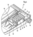
- the laterally from the folding table 10 projecting mounting pins 16 are shown in enlargement in Figure 4. They have cylindrical bearing surfaces 56, with which they eino in half-bearings 58 in the lower part 26 and in just such, not visible Halblagem in the upper part of the folding table 10. In rotationally fixed attachment of the laterally from the folding table 10 protruding part of the mounting pins 16 in not shown receptacles of the folding table 10 is pivotally mounted about the mounting pins 16.
- a slider 60 is provided in the lower part 26 of the folding table 10 at each mounting pin 16.
- the slider 60 is guided in a slide guide 62 radially to the mounting pin 16 slidably in the folding table 10.
- a bent to an oval leaf spring 64 presses with its two free ends 66 against the slider 60 and thereby the slider 60 radially against the mounting pin 16.
- the double bow spring 64 is inserted into a receptacle 68 in the lower part 26 of the folding table 10.
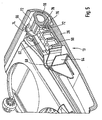
- a central portion 70 of the mounting pins 16 located between the cylindrical bearing surfaces 56 is out of round, the shape of this central portion 70 is best seen in Figure 5, which shows a longitudinal section through the slider 60 and a radial section through the mounting pin 16 in the same sectional plane.
- the central portion 70 of the mounting pin 16 has two secant surfaces 72, which are arranged approximately at right angles to each other. Against one of the two secant surfaces 72 pushes the slider 60 in the position of use of the folding table 10, against the other secant surface 72 pushes the slider 60 in the non-use position of the folding table 10. In Figures 4 and 5, the position of use of the folding table 10 is shown.
- the slider 60 For pivoting the folding table 10 from the position of use in the non-use position and vice versa, the slider 60 must overcome a bead 74 which is formed axially parallel and integrally formed on the central portion 70 of the mounting pin 16 between the two secant surfaces 72. The slider 60 thereby holds the folding table 10 in the position of use and the non-use position.
- the mounting pin 16 has a stop 76 in the form of an outwardly extending, extending in the longitudinal direction of the mounting pin 16 nose.
- the slider 60 is located on a stop 78 of the mounting pin 16 with a step 78 which is formed on its end face. The step 78 and the stop 76 limit the pivot angle of the folding table 10 when folded down into the position of use so that the folding table 10 is horizontal.
- the stop 76 and the step 78 are not arranged radially to the mounting pin 16, but at an angle to the radial.
- the stop 76 and the step 78 thus form inclined surfaces. This causes that upon overloading the folding table 10, the stopper 76 pushes the slider 60 from the mounting pin 16, so that the folding table 10 pivots about the horizontal position of use down.
- the inclined surfaces formed by the stop 76 and the step 78 are aligned and a spring force of the leaf spring 64 is selected so that the stop 76 only from a limit load, the considerably over a usual, by on the folding table 10 parked food, drinks or other objects applied load, folds down.
- the limit load, beyond which the folding table 10 folds down, is for example 13 kg.
- the folding down the folding table 10 down when overloaded is provided so that the folding table 10 yields, when in a crash, a passenger abuts against the folding table 10. The risk of injury is thereby reduced.
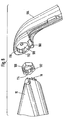
- the folding table 10 has two adapter rings 100 which can be placed on the lateral fastening pins 16 of the folding table 10 in a form-fitting manner (FIG. 6).
- the mounting pins 16 have in the illustrated embodiment, an irregular multi-tooth contour, to which the adapter ring 100 is placed with a complementary multi-tooth contour 102 on its inside.
- the multi-tooth contours 102 of the mounting pin 16 and the adapter ring 100 cause a positive engagement of the adapter ring 100 on the mounting pin 16, which defines a unique angular position of the adapter ring 100 on the mounting pin 16.
- two holding struts 104 are provided in the illustrated embodiment, which are arranged laterally of the folding table 10.
- the retaining struts 104 are attached to a fixed, lower part of the passenger seat, not shown, and extend obliquely up to the mounting pins 16.
- the support struts 104 receptacles 106, in which the adapter rings 100 are positively inserted.
- a perimeter of the receptacles 106 has four sides 108 of an imaginary, irregular hexagon, which are completed by a concavely curved surface 110. In one of the four sides 108 of the imaginary hexagon, a groove 112 is attached.
- An outer periphery of the adapter ring 100 is shaped complementarily to the receptacle 106, wherein an outwardly projecting pin 114 is provided for engagement in the groove 112.
- the shape of the receptacle 106 and the outside of the adapter ring 100 causes a positive engagement with a unique angular position of the adapter ring 100 with respect to the support strut 104.
- the angular position of the mounting pin 16 of the folding table 10 to the support strut 104 is clearly defined and thus the horizontal Use position of the folding table 10 fixed.
- FIGS. 7 and 8 show a second embodiment of a folding table 10 according to the invention in the position of use (FIG. 7) and in the position of non-use (FIG. 8).
- a holder 80 in the form of a retaining ring to the side of a slot 82 from the folding table 10 extendable attached to the folding table 10.
- the holder 80 has an integral with him push rod 83 circular cross-section, which is guided in rod holders 84 in the folding table 10 slidably.
- a radially projecting from the push rod 82 nose 86 engages in a longitudinal direction of the sliding rod 82 extending groove 88 in the folding table 10 and holds the holder 80 against rotation on the folding table 10.
- the holder 80 In order to pivot the holder 80 relative to the folding table 10, the holder 80th pulled laterally out of the folding table 10 via its position of use shown in Figure 6, whereby the nose 86 is released from the groove 88 and the holder 80 is pivotable.
- the holder 80 can now be given away to the underside of the folding table 10, so that it occupies a horizontal position of use in the non-use position of the folding table 10 shown in FIG.
- a support 90 is attached on the holder 80.
- the support 90 is pivotally connected via a pivot connection 92 with the holder 80, it pivots by gravity from Holder 80 down and supports a set in the holder 80 beverage container.
- folding table 10 shown in Figures 7 and 8 is constructed in accordance with the folding table shown in Figures 1 to 5 and works in the same way. To avoid repetition in this regard, reference is made to the above explanations to Figures 1 to 5.
Landscapes
- Engineering & Computer Science (AREA)
- Transportation (AREA)
- Mechanical Engineering (AREA)
- Aviation & Aerospace Engineering (AREA)
- Physics & Mathematics (AREA)
- Thermal Sciences (AREA)
- Passenger Equipment (AREA)
- Chair Legs, Seat Parts, And Backrests (AREA)
- Seats For Vehicles (AREA)
- Vehicle Step Arrangements And Article Storage (AREA)
Claims (12)
- Table pliante (10) destinée à être montée sur la face arrière d'un dossier d'un siège de passager dans un omnibus ou un avion, la table pliante présentant une articulation pivotante permettant de pivoter la table pliante entre une position de non utilisation dans laquelle la table pliante s'applique sensiblement contre la face arrière du dossier du siège de passager et une position d'utilisation dans laquelle la table pliante (10) fait saillie approximativement horizontalement de la face arrière du dossier du siège de passager, la table pliante (10) présentant un support (20 ; 80) pour un récipient pour boisson, et le support (20 ; 80) étant connecté à la table pliante (10) de manière mobile par le biais d'un guide (28 ; 82, 84), de sorte que le support (20 ; 80) puisse être déplacé d'avant en arrière dans la position d'utilisation de la table pliante (10) entre une position de non utilisation dans laquelle le support (20 ; 80) est enfoncé dans la table pliante (10) et une position d'utilisation dans laquelle un récipient pour boisson peut être inséré dans le support (20 ; 80), caractérisée en ce que le support (20 ; 80) présente un guide (28) avec lequel le support (20 ; 80) est connecté de manière mobile à la table pliante (10), de sorte que le support (20 ; 80) puisse être déplacé d'avant en arrière dans la position de non utilisation de la table pliante (10) entre la position de non utilisation et une deuxième position d'utilisation.
- Table pliante selon la revendication 1, caractérisée en ce que le support (80) présente une glissière (82, 84) avec laquelle le support (80) est monté sur la table pliante (10) de manière à pouvoir être ressorti d'un côté de la table pliante (10).
- Table pliante selon la revendication 1,
caractérisée en ce que le support (20) présente une articulation pivotante (28) en tant que guide, avec laquelle le support (20) est monté sur la table pliante (10) de manière à pouvoir sortir par pivotement suivant un angle de pivotement limité hors d'un côté supérieur de la table pliante (10). - Table pliante selon la revendication 1,
caractérisée en ce que le guide présente une articulation pivotante (28 ; 82, 84) permettant de connecter le support (20 ; 80) à la table pliante (10) de manière à pouvoir pivoter vers le bas suivant un angle de pivotement limité. - Table pliante selon la revendication 3 ou 4,
caractérisée en ce que le support (20) présente un élément de ressort d'ouverture (30) qui fait pivoter le support (20) dans la position d'utilisation et en ce que le support (20) présente un dispositif de verrouillage déverrouillable (38, 40) qui maintient le support (20) verrouillé dans la position de non utilisation, jusqu'à son déverrouillage, à l'encontre de la force de l'élément de ressort d'ouverture (32). - Table pliante selon la revendication 4,
caractérisée en ce que le support (20) présente un appui (44 ; 90) pour le récipient pour boisson, qui peut pivoter vers le bas suivant un angle de pivotement limité depuis le support (20 ; 80) par une articulation pivotante (28 ; 92) dans la position de non utilisation de la table pliante (10) et dans la position d'utilisation du support (20 ; 80). - Table pliante selon la revendication 6,
caractérisée en ce que l'appui (44) présente un élément à ressort (32) qui fait pivoter l'appui (44) vers le bas. - Table pliante selon la revendication 7,
caractérisée en ce qu'un élément de ressort d'ouverture (32) du support (80) fait en même temps pivoter l'appui (44) vers le bas. - Table pliante destinée à être montée sur la face arrière d'un dossier d'un siège de passager dans un omnibus ou un avion, la table pliante présentant une articulation pivotante permettant de pivoter la table pliante entre une position de non utilisation dans laquelle la table pliante s'applique sensiblement contre la face arrière du dossier du siège de passager et une position d'utilisation dans laquelle la table pliante fait saillie approximativement horizontalement de la face arrière du dossier du siège de passager, selon l'une quelconque des revendications précédentes, caractérisée en ce que la table pliante (10) présente une ferrure de sécurité (16, 60, 64) avec une butée (76), qui limite l'angle de pivotement de la table pliante (10) dans la direction de la position d'utilisation, et en ce que la butée (76) peut être surmontée en dépassant une sollicitation limite agissant sur la table pliante (10) dans la direction de la position d'utilisation.
- Table pliante selon la revendication 9,
caractérisée en ce que la butée (76) dépasse du pourtour d'un tourillon (16) autour duquel la table pliante (10) peut pivoter entre la position de non utilisation et la position d'utilisation et en ce que la butée (76) coopère avec un coulisseau (60) qui est pressé par un ressort de coulisseau (64) contre le tourillon (16), la butée (76) pressant le coulisseau (60) hors d'engagement en cas de dépassement de la sollicitation limite agissant sur la table pliante (10). - Table pliante selon la revendication 1 ou 9,
caractérisée en ce que la table pliante (10) présente un adaptateur (100) qui peut être monté sur la table pliante (10) par engagement par coopération de forme dans une position angulaire univoque par rapport à un axe de pivotement (18) de l'articulation pivotante, et en ce que l'adaptateur (100) peut être monté sur la face arrière du dossier du siège de passager par engagement par coopération de forme dans une position angulaire univoque sur un support de table pliante (104). - Table pliante selon la revendication 11,
caractérisée en ce que l'adaptateur est une bague d'adaptateur (100) avec un contour interne (102) et un contour externe, qui provoquent l'engagement par coopération de forme dans la position angulaire univoque.
Priority Applications (1)
| Application Number | Priority Date | Filing Date | Title |
|---|---|---|---|
| EP05017267A EP1602528A3 (fr) | 1998-07-28 | 1999-07-07 | Table pliante à attacher à la face arrière du dossier d'un siège de passager dans un omnibus ou un avion |
Applications Claiming Priority (2)
| Application Number | Priority Date | Filing Date | Title |
|---|---|---|---|
| DE19833888A DE19833888C1 (de) | 1998-07-28 | 1998-07-28 | Klapptisch zur Anbringung an einer Rückseite einer Rückenlehne eines Fahrgastsitzes in einem Omnibus oder Flugzeug |
| DE19833888 | 1998-07-28 |
Related Child Applications (1)
| Application Number | Title | Priority Date | Filing Date |
|---|---|---|---|
| EP05017267A Division EP1602528A3 (fr) | 1998-07-28 | 1999-07-07 | Table pliante à attacher à la face arrière du dossier d'un siège de passager dans un omnibus ou un avion |
Publications (3)
| Publication Number | Publication Date |
|---|---|
| EP0976609A2 EP0976609A2 (fr) | 2000-02-02 |
| EP0976609A3 EP0976609A3 (fr) | 2000-06-21 |
| EP0976609B1 true EP0976609B1 (fr) | 2006-03-22 |
Family
ID=7875541
Family Applications (2)
| Application Number | Title | Priority Date | Filing Date |
|---|---|---|---|
| EP05017267A Withdrawn EP1602528A3 (fr) | 1998-07-28 | 1999-07-07 | Table pliante à attacher à la face arrière du dossier d'un siège de passager dans un omnibus ou un avion |
| EP99113129A Expired - Lifetime EP0976609B1 (fr) | 1998-07-28 | 1999-07-07 | Table pliante à attacher à la face arrière d'un dossier d'un siège de passager dans un omnibus ou un avion |
Family Applications Before (1)
| Application Number | Title | Priority Date | Filing Date |
|---|---|---|---|
| EP05017267A Withdrawn EP1602528A3 (fr) | 1998-07-28 | 1999-07-07 | Table pliante à attacher à la face arrière du dossier d'un siège de passager dans un omnibus ou un avion |
Country Status (10)
| Country | Link |
|---|---|
| US (1) | US6279992B1 (fr) |
| EP (2) | EP1602528A3 (fr) |
| JP (1) | JP3410687B2 (fr) |
| KR (1) | KR20000011854A (fr) |
| CN (1) | CN1129535C (fr) |
| AT (1) | ATE320940T1 (fr) |
| DE (2) | DE19833888C1 (fr) |
| ES (1) | ES2260871T3 (fr) |
| PT (1) | PT976609E (fr) |
| TR (1) | TR199901785A3 (fr) |
Cited By (1)
| Publication number | Priority date | Publication date | Assignee | Title |
|---|---|---|---|---|
| USD635502S1 (en) | 2009-12-17 | 2011-04-05 | Air New Zealand Limited | Cup holder |
Families Citing this family (46)
| Publication number | Priority date | Publication date | Assignee | Title |
|---|---|---|---|---|
| DE20207355U1 (de) * | 2002-05-08 | 2002-08-29 | Berger, Georg, 44797 Bochum | Klapptisch für einen Sitz in einem Verkehrsmittel |
| KR100891993B1 (ko) | 2002-06-27 | 2009-04-08 | 삼성전자주식회사 | 컴퓨터 |
| US6877806B2 (en) | 2002-10-21 | 2005-04-12 | E & E Manufacturing Company, Inc. | Folding tray assembly |
| US20080208694A1 (en) * | 2003-08-08 | 2008-08-28 | Baggott David I | Concession tray |
| US7341005B2 (en) * | 2003-08-08 | 2008-03-11 | Baggott David I | Concession tray |
| DE102005061651A1 (de) * | 2005-12-22 | 2007-06-28 | Volkswagen Ag | Halter für Flaschen, Getränkedosen, Trinkgefässe o.dgl. |
| US20070200414A1 (en) * | 2006-02-27 | 2007-08-30 | Pozzi Alexander N | Vehicle seats and components thereof |
| US8210605B2 (en) * | 2006-03-21 | 2012-07-03 | Be Aerospace, Inc. | Holster for portable IFE device |
| FR2908702B1 (fr) * | 2006-11-17 | 2008-12-19 | Renault Sas | Agencement de porte-recipient pour une tablette de vehicule automobile |
| US7740312B2 (en) * | 2006-11-28 | 2010-06-22 | Erie Works Corp. | Portable drink holder with internal reader light |
| JP2008155661A (ja) * | 2006-12-20 | 2008-07-10 | Toyoda Gosei Co Ltd | 車両用のスライドコンソール |
| DE102007048687A1 (de) * | 2007-10-10 | 2009-04-16 | Recaro Aircraft Seating Gmbh & Co. Kg | Sitzvorrichtung, insbesondere Flugzeugsitzvorrichtung |
| JP5175572B2 (ja) * | 2008-02-08 | 2013-04-03 | トヨタ紡織株式会社 | 車両用シートのテーブル |
| CN101323266B (zh) * | 2008-07-24 | 2011-04-13 | 上海延锋江森座椅有限公司 | 汽车座椅桌板 |
| DE102008057790A1 (de) * | 2008-11-17 | 2010-05-20 | Johnson Controls Gmbh | Fahrzeugsitz mit einem an der Rückenlehne angeordneten Tisch |
| DE102009012773A1 (de) * | 2009-03-13 | 2010-09-16 | Koki Technik Seating Systems Gmbh | Fahrzeugsitz, insbesondere für ein Kraftfahrzeug |
| DE102009042879A1 (de) * | 2009-09-24 | 2011-03-31 | GM Global Technology Operations, Inc., Detroit | Klapptisch für ein Fahrzeug |
| DE102009043071A1 (de) * | 2009-09-25 | 2011-03-31 | Volkswagen Ag | Cupholdermodul für ein Kraftfahrzeug |
| JP5607333B2 (ja) * | 2009-10-07 | 2014-10-15 | テイ・エス テック株式会社 | 折り畳みテーブル |
| US7971929B2 (en) * | 2009-10-28 | 2011-07-05 | Be Aerospace, Inc. | Meal tray with advertising display |
| DE102010008718A1 (de) | 2010-02-20 | 2010-11-04 | Daimler Ag | Klapptisch für ein Kraftfahrzeug |
| DE102010022442A1 (de) * | 2010-06-01 | 2011-12-01 | Volkswagen Ag | Anbauvorrichtung für den Innenraum eines Kraftfahrzeugs |
| CN102085349B (zh) * | 2011-01-03 | 2012-03-14 | 山东大学威海分校 | 一种复方枸杞子制剂的制备方法及其用途 |
| FR2974771B1 (fr) * | 2011-05-04 | 2013-05-31 | Peugeot Citroen Automobiles Sa | Tablette extractible pour un vehicule automobile |
| DE102011082061A1 (de) * | 2011-09-02 | 2013-03-07 | Airbus Operations Gmbh | Tischanordnung für ein Luft- oder Raumfahrzeug |
| EP2586655B1 (fr) * | 2011-10-25 | 2016-11-30 | IVECO S.p.A. | Table rétractable, spécialement pour un véhicule industriel ou commercial |
| DE102012104293B4 (de) * | 2012-05-16 | 2024-05-16 | Kokinetics Gmbh | Überlastsicherung und eine Verwendung hierfür |
| DE102012012850B4 (de) * | 2012-06-26 | 2015-01-08 | Johnson Controls Gmbh | Fahrzeugsitz |
| US9527456B2 (en) * | 2012-11-05 | 2016-12-27 | Kinetix Ag | Device for retaining flat, approximately rectangular appliances such as tablet computers or mobile telephones in the interior of a motor vehicle |
| CN103407396B (zh) * | 2013-07-29 | 2016-01-27 | 天津博信汽车零部件有限公司 | 一种汽车座椅扶手杯托安装结构 |
| DE102014207307A1 (de) | 2014-04-16 | 2015-10-22 | Volkswagen Aktiengesellschaft | Überlastsicherung für einen Klapptisch, Klapptisch und Fahrzeugsitz |
| DE102014210861A1 (de) * | 2014-06-06 | 2015-12-17 | Lufthansa Technik Ag | Flugzeugsitz und Haltevorrichtung |
| KR101595732B1 (ko) | 2014-11-07 | 2016-02-19 | 주식회사 동강홀딩스 | 자동차의 테이블용 이중 홀딩 컵홀더 |
| US9764844B2 (en) | 2015-04-13 | 2017-09-19 | Encore Seats, Inc. | Aircraft seating assembly |
| GB2543774B (en) * | 2015-10-27 | 2018-04-18 | Ford Global Tech Llc | Stowable table |
| US10144515B2 (en) | 2016-04-01 | 2018-12-04 | Encore Seats, Inc. | Aircraft seating assembly and components |
| US9751630B1 (en) * | 2016-06-28 | 2017-09-05 | Recaro Aircraft Seating Gmbh & Co. Kg | Tray table device |
| CN107054188B (zh) * | 2017-05-11 | 2023-06-27 | 安道拓(重庆)汽车部件有限公司 | 具有收折小桌板的汽车座椅 |
| CN107161058B (zh) * | 2017-05-11 | 2022-12-27 | 重庆安道拓汽车部件系统有限公司 | 汽车座椅靠背收折式小桌板 |
| JP6601468B2 (ja) * | 2017-09-22 | 2019-11-06 | カシオ計算機株式会社 | 飛行装置、飛行方法及びプログラム |
| GB2579604B (en) | 2018-12-05 | 2022-06-15 | Safran Seats Gb Ltd | Drinking receptacle holder |
| JP7298740B1 (ja) * | 2022-03-11 | 2023-06-27 | 豊田合成株式会社 | コンソールボックス |
| US12441473B2 (en) * | 2022-09-07 | 2025-10-14 | B/E Aerospace, Inc. | System including stowable cupholder apparatus |
| DE102022128321A1 (de) * | 2022-10-26 | 2024-05-02 | Grammer Aktiengesellschaft | Tischeinrichtung |
| CN219835391U (zh) * | 2022-11-04 | 2023-10-17 | 嘉顿契约有限责任公司 | 折叠系统、具有折叠系统的桌子和椅子 |
| CN116448446A (zh) * | 2023-03-17 | 2023-07-18 | 上海菲格瑞特汽车科技股份有限公司 | 一种模型车折叠小桌板盖板联动开启装置及开启方法 |
Family Cites Families (16)
| Publication number | Priority date | Publication date | Assignee | Title |
|---|---|---|---|---|
| US3773381A (en) * | 1972-05-08 | 1973-11-20 | Universal Oil Prod Co | Compact tray table |
| DE7527789U (de) * | 1975-09-03 | 1976-04-15 | Gebr. Happich Gmbh, 5600 Wuppertal | Klapptisch |
| DE2743172C2 (de) * | 1977-09-26 | 1982-12-16 | Ignaz Vogel Gmbh Und Co Kg - Fahrzeugsitze, 7500 Karlsruhe | Fahrgastsitz-Tischplatte |
| US4583707A (en) * | 1984-09-18 | 1986-04-22 | Assembled Components Company, Inc. | Storage holder for a container |
| DE3942629A1 (de) * | 1989-12-22 | 1991-06-27 | Wilhelm Wamhoff | Schwenktischanordnung zur montage an einem fahrzeugteil |
| US5092652A (en) * | 1990-10-30 | 1992-03-03 | Macaluso Raymond R | Extendable airline turbulence tray |
| DE4125783A1 (de) * | 1991-08-03 | 1993-02-04 | Askon Aldenhoff & Schnell Kons | Tischanordnung zur montage an einem fahrzeugteil |
| DE4126427C1 (fr) * | 1991-08-09 | 1992-11-26 | Mercedes-Benz Aktiengesellschaft, 7000 Stuttgart, De | |
| DE4224700A1 (de) * | 1992-07-25 | 1994-01-27 | Euwe Eugen Wexler Gmbh | Haltevorrichtung für Getränkebehälter |
| DE4344372C2 (de) * | 1993-12-24 | 1995-11-30 | Daimler Benz Ag | An einer aufragenden Wand in einem Kraftwagen angeordneter Halter |
| JP3003598U (ja) | 1994-04-27 | 1994-10-25 | 株式会社芋谷工業 | 自動車用テーブル |
| DE19508987A1 (de) * | 1995-03-13 | 1996-04-11 | Daimler Benz Ag | Getränkehalter an einer Klappe |
| FR2737447B1 (fr) * | 1995-08-04 | 1997-12-05 | Blanc Rosset Andre Jules | Accessoire du type plate-forme utilitaire pour vehicule automobile |
| DE29512686U1 (de) * | 1995-08-07 | 1996-01-18 | Federnwerke Marienberg Gmbh, 09496 Marienberg | Verstellmechanismus für eine Kraftfahrzeug-Mittelarmlehne |
| US5876092A (en) * | 1997-12-05 | 1999-03-02 | Industrial Technology Research Institute | Foldaway table behind the backrest of a seat |
| US6085666A (en) * | 1998-03-27 | 2000-07-11 | Prince Technology Corporation | Articulating tray assembly |
-
1998
- 1998-07-28 DE DE19833888A patent/DE19833888C1/de not_active Expired - Fee Related
-
1999
- 1999-07-07 EP EP05017267A patent/EP1602528A3/fr not_active Withdrawn
- 1999-07-07 AT AT99113129T patent/ATE320940T1/de not_active IP Right Cessation
- 1999-07-07 EP EP99113129A patent/EP0976609B1/fr not_active Expired - Lifetime
- 1999-07-07 PT PT99113129T patent/PT976609E/pt unknown
- 1999-07-07 ES ES99113129T patent/ES2260871T3/es not_active Expired - Lifetime
- 1999-07-07 DE DE59913239T patent/DE59913239D1/de not_active Expired - Fee Related
- 1999-07-21 KR KR1019990029449A patent/KR20000011854A/ko not_active Ceased
- 1999-07-21 US US09/358,295 patent/US6279992B1/en not_active Expired - Fee Related
- 1999-07-27 TR TR1999/01785A patent/TR199901785A3/tr unknown
- 1999-07-27 JP JP21248699A patent/JP3410687B2/ja not_active Expired - Fee Related
- 1999-07-28 CN CN99111867A patent/CN1129535C/zh not_active Expired - Fee Related
Cited By (1)
| Publication number | Priority date | Publication date | Assignee | Title |
|---|---|---|---|---|
| USD635502S1 (en) | 2009-12-17 | 2011-04-05 | Air New Zealand Limited | Cup holder |
Also Published As
| Publication number | Publication date |
|---|---|
| JP3410687B2 (ja) | 2003-05-26 |
| EP0976609A3 (fr) | 2000-06-21 |
| CN1247141A (zh) | 2000-03-15 |
| DE19833888C1 (de) | 2000-01-27 |
| CN1129535C (zh) | 2003-12-03 |
| DE59913239D1 (de) | 2006-05-11 |
| ES2260871T3 (es) | 2006-11-01 |
| ATE320940T1 (de) | 2006-04-15 |
| EP1602528A3 (fr) | 2009-06-03 |
| US6279992B1 (en) | 2001-08-28 |
| JP2000052832A (ja) | 2000-02-22 |
| EP0976609A2 (fr) | 2000-02-02 |
| HK1024212A1 (en) | 2000-10-05 |
| KR20000011854A (ko) | 2000-02-25 |
| EP1602528A2 (fr) | 2005-12-07 |
| PT976609E (pt) | 2006-06-30 |
| TR199901785A2 (xx) | 2000-02-21 |
| TR199901785A3 (tr) | 2000-02-21 |
Similar Documents
| Publication | Publication Date | Title |
|---|---|---|
| EP0976609B1 (fr) | Table pliante à attacher à la face arrière d'un dossier d'un siège de passager dans un omnibus ou un avion | |
| DE3923989C2 (de) | Rücksitzanordnung für ein Kraftfahrzeug | |
| EP1431112B1 (fr) | Tablette pliante pour véhicule. | |
| EP0697308B1 (fr) | Dispositif pour tenir deux récipients de boissons dans la console centrale d'un véhicule à moteur | |
| DE102012012850B4 (de) | Fahrzeugsitz | |
| EP3536549A1 (fr) | Siège pour enfant ou siège pour bébé destiné à être monté sur un siège de véhicule automobile | |
| EP1902949B1 (fr) | Agencement de table pliante | |
| DE112017004857T5 (de) | Von der Innenverkleidung eines Fahrzeugs anbringbarer und abnehmbarer tragbarer Tisch | |
| EP1556248B1 (fr) | Porte-gobelet | |
| EP1176050A2 (fr) | Dispositif de support d'un réceptacle de boissons | |
| EP0730994B1 (fr) | Support pour un conteneur de boisson | |
| DE102021134568A1 (de) | Becherhaltervorrichtung vom verdeckten typ, fahrzeugarmstütze, die die haltervorrichtung aufweist, und transportmittel, welches diese aufweist | |
| DE19901072C1 (de) | Staubehälter für ein Kraftfahrzeug | |
| DE29920019U1 (de) | Vorrichtung zur Halterung von Getränkedosen | |
| DE19821313C2 (de) | Halterung für einen Getränkebehälter in einem Kraftwagen | |
| EP1304257B1 (fr) | Support pour un récipient de boisson | |
| DE10319933B4 (de) | Klapptisch für ein Fahrzeug, insbesondere für ein Kraftfahrzeug | |
| DE19546543B4 (de) | An einer hinsichtlich ihrer Neigung verstellbaren Rückenlehne eines Sitzes anzubringender Klapptisch | |
| DE20204882U1 (de) | Halter für einen Getränkebehälter | |
| EP3924252B1 (fr) | Dispositif de siège pour aéronef | |
| DE4228848C1 (de) | Haltevorrichtung für Getränkeflaschen an einem Fahrzeugsitz mit Armlehne | |
| DE19630528A1 (de) | Vorrichtung zum Halten zweier Getränkebehälter in der Mittelkonsole eines Kraftwagens | |
| DE10047741A1 (de) | Fahrzeugsitz mit abnehmbarer Kopfstütze | |
| DE102010008718A1 (de) | Klapptisch für ein Kraftfahrzeug | |
| DE20004980U1 (de) | Mittelkonsole |
Legal Events
| Date | Code | Title | Description |
|---|---|---|---|
| PUAI | Public reference made under article 153(3) epc to a published international application that has entered the european phase |
Free format text: ORIGINAL CODE: 0009012 |
|
| AK | Designated contracting states |
Kind code of ref document: A2 Designated state(s): AT BE CH CY DE DK ES FI FR GB GR IE IT LI LU MC NL PT SE |
|
| AX | Request for extension of the european patent |
Free format text: AL;LT;LV;MK;RO;SI |
|
| PUAL | Search report despatched |
Free format text: ORIGINAL CODE: 0009013 |
|
| AK | Designated contracting states |
Kind code of ref document: A3 Designated state(s): AT BE CH CY DE DK ES FI FR GB GR IE IT LI LU MC NL PT SE |
|
| AX | Request for extension of the european patent |
Free format text: AL;LT;LV;MK;RO;SI |
|
| 17P | Request for examination filed |
Effective date: 20001024 |
|
| AKX | Designation fees paid |
Free format text: AT BE CH CY DE DK ES FI FR GB GR IE IT LI LU MC NL PT SE |
|
| 17Q | First examination report despatched |
Effective date: 20050228 |
|
| GRAC | Information related to communication of intention to grant a patent modified |
Free format text: ORIGINAL CODE: EPIDOSCIGR1 |
|
| GRAP | Despatch of communication of intention to grant a patent |
Free format text: ORIGINAL CODE: EPIDOSNIGR1 |
|
| GRAS | Grant fee paid |
Free format text: ORIGINAL CODE: EPIDOSNIGR3 |
|
| GRAA | (expected) grant |
Free format text: ORIGINAL CODE: 0009210 |
|
| RAP1 | Party data changed (applicant data changed or rights of an application transferred) |
Owner name: DAIMLERCHRYSLER AG |
|
| AK | Designated contracting states |
Kind code of ref document: B1 Designated state(s): AT BE CH CY DE DK ES FI FR GB GR IE IT LI LU MC NL PT SE |
|
| PG25 | Lapsed in a contracting state [announced via postgrant information from national office to epo] |
Ref country code: IE Free format text: LAPSE BECAUSE OF FAILURE TO SUBMIT A TRANSLATION OF THE DESCRIPTION OR TO PAY THE FEE WITHIN THE PRESCRIBED TIME-LIMIT Effective date: 20060322 Ref country code: GB Free format text: LAPSE BECAUSE OF FAILURE TO SUBMIT A TRANSLATION OF THE DESCRIPTION OR TO PAY THE FEE WITHIN THE PRESCRIBED TIME-LIMIT Effective date: 20060322 |
|
| REG | Reference to a national code |
Ref country code: GB Ref legal event code: FG4D Free format text: NOT ENGLISH |
|
| REG | Reference to a national code |
Ref country code: CH Ref legal event code: EP |
|
| REG | Reference to a national code |
Ref country code: IE Ref legal event code: FG4D Free format text: LANGUAGE OF EP DOCUMENT: GERMAN |
|
| REF | Corresponds to: |
Ref document number: 59913239 Country of ref document: DE Date of ref document: 20060511 Kind code of ref document: P |
|
| REG | Reference to a national code |
Ref country code: SE Ref legal event code: TRGR |
|
| PG25 | Lapsed in a contracting state [announced via postgrant information from national office to epo] |
Ref country code: DK Free format text: LAPSE BECAUSE OF FAILURE TO SUBMIT A TRANSLATION OF THE DESCRIPTION OR TO PAY THE FEE WITHIN THE PRESCRIBED TIME-LIMIT Effective date: 20060622 |
|
| REG | Reference to a national code |
Ref country code: PT Ref legal event code: SC4A Effective date: 20060427 |
|
| PG25 | Lapsed in a contracting state [announced via postgrant information from national office to epo] |
Ref country code: MC Free format text: LAPSE BECAUSE OF NON-PAYMENT OF DUE FEES Effective date: 20060731 Ref country code: LI Free format text: LAPSE BECAUSE OF NON-PAYMENT OF DUE FEES Effective date: 20060731 Ref country code: CH Free format text: LAPSE BECAUSE OF NON-PAYMENT OF DUE FEES Effective date: 20060731 |
|
| GBV | Gb: ep patent (uk) treated as always having been void in accordance with gb section 77(7)/1977 [no translation filed] |
Effective date: 20060322 |
|
| ET | Fr: translation filed | ||
| REG | Reference to a national code |
Ref country code: ES Ref legal event code: FG2A Ref document number: 2260871 Country of ref document: ES Kind code of ref document: T3 |
|
| REG | Reference to a national code |
Ref country code: IE Ref legal event code: FD4D |
|
| REG | Reference to a national code |
Ref country code: CH Ref legal event code: PL |
|
| PLBE | No opposition filed within time limit |
Free format text: ORIGINAL CODE: 0009261 |
|
| STAA | Information on the status of an ep patent application or granted ep patent |
Free format text: STATUS: NO OPPOSITION FILED WITHIN TIME LIMIT |
|
| 26N | No opposition filed |
Effective date: 20061227 |
|
| BECA | Be: change of holder's address |
Owner name: *DAIMLER A.G.,D-70546 STUTTGART Effective date: 20060322 |
|
| BECN | Be: change of holder's name |
Owner name: *DAIMLER A.G. Effective date: 20060322 |
|
| REG | Reference to a national code |
Ref country code: PT Ref legal event code: PD4A Owner name: DAIMLER AG, DE Effective date: 20080228 |
|
| PG25 | Lapsed in a contracting state [announced via postgrant information from national office to epo] |
Ref country code: GR Free format text: LAPSE BECAUSE OF FAILURE TO SUBMIT A TRANSLATION OF THE DESCRIPTION OR TO PAY THE FEE WITHIN THE PRESCRIBED TIME-LIMIT Effective date: 20060623 |
|
| NLT1 | Nl: modifications of names registered in virtue of documents presented to the patent office pursuant to art. 16 a, paragraph 1 |
Owner name: DAIMLER AG |
|
| PG25 | Lapsed in a contracting state [announced via postgrant information from national office to epo] |
Ref country code: FI Free format text: LAPSE BECAUSE OF FAILURE TO SUBMIT A TRANSLATION OF THE DESCRIPTION OR TO PAY THE FEE WITHIN THE PRESCRIBED TIME-LIMIT Effective date: 20060322 |
|
| PG25 | Lapsed in a contracting state [announced via postgrant information from national office to epo] |
Ref country code: LU Free format text: LAPSE BECAUSE OF NON-PAYMENT OF DUE FEES Effective date: 20060707 |
|
| REG | Reference to a national code |
Ref country code: PT Ref legal event code: TE4A Owner name: DAIMLER AG, DE Effective date: 20080813 |
|
| PGFP | Annual fee paid to national office [announced via postgrant information from national office to epo] |
Ref country code: PT Payment date: 20080626 Year of fee payment: 10 |
|
| PGFP | Annual fee paid to national office [announced via postgrant information from national office to epo] |
Ref country code: ES Payment date: 20080729 Year of fee payment: 10 |
|
| PG25 | Lapsed in a contracting state [announced via postgrant information from national office to epo] |
Ref country code: CY Free format text: LAPSE BECAUSE OF FAILURE TO SUBMIT A TRANSLATION OF THE DESCRIPTION OR TO PAY THE FEE WITHIN THE PRESCRIBED TIME-LIMIT Effective date: 20060322 |
|
| PGFP | Annual fee paid to national office [announced via postgrant information from national office to epo] |
Ref country code: NL Payment date: 20080716 Year of fee payment: 10 Ref country code: IT Payment date: 20080724 Year of fee payment: 10 Ref country code: FR Payment date: 20080715 Year of fee payment: 10 Ref country code: AT Payment date: 20080715 Year of fee payment: 10 |
|
| PGFP | Annual fee paid to national office [announced via postgrant information from national office to epo] |
Ref country code: SE Payment date: 20080714 Year of fee payment: 10 Ref country code: BE Payment date: 20080814 Year of fee payment: 10 |
|
| PGFP | Annual fee paid to national office [announced via postgrant information from national office to epo] |
Ref country code: DE Payment date: 20090722 Year of fee payment: 11 |
|
| REG | Reference to a national code |
Ref country code: FR Ref legal event code: CD Ref country code: FR Ref legal event code: CA |
|
| REG | Reference to a national code |
Ref country code: PT Ref legal event code: MM4A Free format text: LAPSE DUE TO NON-PAYMENT OF FEES Effective date: 20100107 |
|
| BERE | Be: lapsed |
Owner name: *DAIMLER A.G. Effective date: 20090731 |
|
| EUG | Se: european patent has lapsed | ||
| NLV4 | Nl: lapsed or anulled due to non-payment of the annual fee |
Effective date: 20100201 |
|
| REG | Reference to a national code |
Ref country code: FR Ref legal event code: ST Effective date: 20100331 |
|
| PG25 | Lapsed in a contracting state [announced via postgrant information from national office to epo] |
Ref country code: PT Free format text: LAPSE BECAUSE OF NON-PAYMENT OF DUE FEES Effective date: 20100107 Ref country code: FR Free format text: LAPSE BECAUSE OF NON-PAYMENT OF DUE FEES Effective date: 20090731 |
|
| PG25 | Lapsed in a contracting state [announced via postgrant information from national office to epo] |
Ref country code: BE Free format text: LAPSE BECAUSE OF NON-PAYMENT OF DUE FEES Effective date: 20090731 Ref country code: AT Free format text: LAPSE BECAUSE OF NON-PAYMENT OF DUE FEES Effective date: 20090707 |
|
| REG | Reference to a national code |
Ref country code: ES Ref legal event code: FD2A Effective date: 20090708 |
|
| PG25 | Lapsed in a contracting state [announced via postgrant information from national office to epo] |
Ref country code: ES Free format text: LAPSE BECAUSE OF NON-PAYMENT OF DUE FEES Effective date: 20090708 |
|
| PG25 | Lapsed in a contracting state [announced via postgrant information from national office to epo] |
Ref country code: IT Free format text: LAPSE BECAUSE OF NON-PAYMENT OF DUE FEES Effective date: 20090707 |
|
| PG25 | Lapsed in a contracting state [announced via postgrant information from national office to epo] |
Ref country code: DE Free format text: LAPSE BECAUSE OF NON-PAYMENT OF DUE FEES Effective date: 20110201 |
|
| REG | Reference to a national code |
Ref country code: DE Ref legal event code: R119 Ref document number: 59913239 Country of ref document: DE Effective date: 20110201 |
|
| PG25 | Lapsed in a contracting state [announced via postgrant information from national office to epo] |
Ref country code: SE Free format text: LAPSE BECAUSE OF NON-PAYMENT OF DUE FEES Effective date: 20090708 |
|
| PG25 | Lapsed in a contracting state [announced via postgrant information from national office to epo] |
Ref country code: NL Free format text: LAPSE BECAUSE OF NON-PAYMENT OF DUE FEES Effective date: 20100201 |