EP0976631A2 - Verfahren und Gerät zur Ermittlung der Reihenfolge von Schienenfahrzeugen in einem Zug - Google Patents
Verfahren und Gerät zur Ermittlung der Reihenfolge von Schienenfahrzeugen in einem Zug Download PDFInfo
- Publication number
- EP0976631A2 EP0976631A2 EP99113998A EP99113998A EP0976631A2 EP 0976631 A2 EP0976631 A2 EP 0976631A2 EP 99113998 A EP99113998 A EP 99113998A EP 99113998 A EP99113998 A EP 99113998A EP 0976631 A2 EP0976631 A2 EP 0976631A2
- Authority
- EP
- European Patent Office
- Prior art keywords
- railcars
- signal
- pneumatic
- train
- railcar
- Prior art date
- Legal status (The legal status is an assumption and is not a legal conclusion. Google has not performed a legal analysis and makes no representation as to the accuracy of the status listed.)
- Withdrawn
Links
- 238000000034 method Methods 0.000 title claims abstract description 43
- 230000004044 response Effects 0.000 claims description 31
- 238000004891 communication Methods 0.000 claims description 26
- 230000009467 reduction Effects 0.000 claims description 24
- 230000003137 locomotive effect Effects 0.000 claims description 16
- 230000008859 change Effects 0.000 claims description 4
- 230000008878 coupling Effects 0.000 claims description 3
- 238000010168 coupling process Methods 0.000 claims description 3
- 238000005859 coupling reaction Methods 0.000 claims description 3
- 238000001514 detection method Methods 0.000 claims description 2
- 230000005540 biological transmission Effects 0.000 claims 1
- 230000003111 delayed effect Effects 0.000 claims 1
- 230000000644 propagated effect Effects 0.000 claims 1
- 230000008569 process Effects 0.000 description 15
- 238000001444 catalytic combustion detection Methods 0.000 description 12
- 230000008901 benefit Effects 0.000 description 4
- 230000001174 ascending effect Effects 0.000 description 3
- 238000005259 measurement Methods 0.000 description 3
- 238000010586 diagram Methods 0.000 description 2
- 230000000694 effects Effects 0.000 description 2
- 238000012545 processing Methods 0.000 description 2
- 230000001902 propagating effect Effects 0.000 description 2
- 238000012360 testing method Methods 0.000 description 2
- 230000004913 activation Effects 0.000 description 1
- 238000013459 approach Methods 0.000 description 1
- 238000010276 construction Methods 0.000 description 1
- 238000003780 insertion Methods 0.000 description 1
- 230000037431 insertion Effects 0.000 description 1
- 239000000463 material Substances 0.000 description 1
- 238000011084 recovery Methods 0.000 description 1
- 230000000630 rising effect Effects 0.000 description 1
- 230000011664 signaling Effects 0.000 description 1
- 239000007787 solid Substances 0.000 description 1
Images


Classifications
-
- B—PERFORMING OPERATIONS; TRANSPORTING
- B61—RAILWAYS
- B61L—GUIDING RAILWAY TRAFFIC; ENSURING THE SAFETY OF RAILWAY TRAFFIC
- B61L15/00—Indicators provided on the vehicle or train for signalling purposes
- B61L15/0018—Communication with or on the vehicle or train
- B61L15/0036—Conductor-based, e.g. using CAN-Bus, train-line or optical fibres
-
- B—PERFORMING OPERATIONS; TRANSPORTING
- B61—RAILWAYS
- B61L—GUIDING RAILWAY TRAFFIC; ENSURING THE SAFETY OF RAILWAY TRAFFIC
- B61L15/00—Indicators provided on the vehicle or train for signalling purposes
- B61L15/0072—On-board train data handling
-
- B—PERFORMING OPERATIONS; TRANSPORTING
- B61—RAILWAYS
- B61L—GUIDING RAILWAY TRAFFIC; ENSURING THE SAFETY OF RAILWAY TRAFFIC
- B61L25/00—Recording or indicating positions or identities of vehicles or trains or setting of track apparatus
- B61L25/02—Indicating or recording positions or identities of vehicles or trains
- B61L25/028—Determination of vehicle position and orientation within a train consist, e.g. serialisation
Definitions
- the present invention generally relates to train control systems and more particularly relates to control systems for trains which include both an intra-train electronic communication system which may be an electric power line, or an RF link, and a brake air line extending along the length of the train, and even more particularly relates to control systems utilizing both such lines.
- an intra-train electronic communication system which may be an electric power line, or an RF link
- a brake air line extending along the length of the train
- the railroads have typically operated trains having only a single air line extending the length of the train.
- This air line was used for both providing a source of compressed air and a medium for propagating braking signals. While this system has been used extensively in the past, it has several drawbacks. Signaling via air pressure messages propagating through the air line has a limited propagation speed. For example, for a 150-car freight train, it may take fifteen seconds or more for a braking message to reach the 150 th car, thereby delaying the full application of the rail car brakes and consequently extending the distance required to stop the train.
- AAR American Association of Rails
- individual railroads have investigated using electronic controlled pneumatic (ECP) brake systems.
- the pneumatic signal propagation may slow to between 600 and 900 feet per second. At 600 feet per second, this pneumatic signal will require about 100 milliseconds to propagate through each car or about fifteen seconds to propagate the length of the train.
- the ECP brake system allows for nearly instantaneous activation of the railcar brakes along the entire length of the train.
- the present invention is a method and apparatus for determining railcar order in a train which is designed to satisfy the aforementioned needs, provide the previously stated objects, include the above-listed features and achieve the already articulated advantages.
- the time, expense and reliability problems associated with manually preparing a railcar order list has been significantly reduced.
- the present invention is a method and apparatus for determining railcar order in a train which utilizes the inherent differences in the propagation velocity of electronic signals and pneumatic signals to determine the railcar order in a train.
- Figure 1 is a simplified schematic diagram of a train, including a leading locomotive followed by numerous trailing railcars where the dark solid line represents an electrical power line extending the length of the train and the two parallel lines extending the length of the train are used to represent a brake air line extending the length of the train.
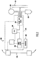
- Figure 2 is a simplified schematic diagram of a typical railcar of the prior art of Figure 1.
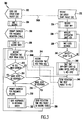
- FIG. 3 is a flowchart of the steps of the method of the present invention.
- FIG. 4 is a flowchart of an alternate method of the present invention.
- an ECP equipped train of the prior art generally designated 100, including a locomotive 102, railcar 104, railcar 106, railcar 108, railcar 110 and railcar 112.
- brake air pipe 120 Extending the length of the train 100 is brake air pipe 120, which is shown by two closely spaced and separated parallel lines extending the length of the train and having a discontinuous section 122 disposed between railcar 108 and railcar 110 to signify the position for insertion of numerous other railcars therebetween.
- Extending the length of the train 100 is electronic power line 130, which is shown by a solid black line having a discontinuous section 132 disposed between railcar 108 and 110 to signify the position for inclusion of numerous other railcars disposed therebetween. It should be noted that the method of the present invention could be accomplished using another form of electronic communication, such as RF links between the railcars and the locomotive or other means of electronic communication.
- the train of Figure 1 is intended to graphically display some of the key components of an ECP equipped train, which is known in the art. A more detailed depiction of the components of a typical ECP system for a typical railcar is shown in Figure 2.
- a Head End Unit (HEU) 140 disposed in the locomotive, may be coupled to both line 130 and pipe 120. HEUs are well known in the art.
- FIG. 2 there is shown a detailed depiction of typical components of a prior art railcar equipped with an ECP system.
- a system generally designated 200 is shown having a brake line 120 and a train line 130, which is an electrical power line and may be 230 volts.
- the train line may also be an electronic communication line.
- brake line 120 Coupled to brake line 120 are air reservoir 220, brake cylinder 222, and electronic pressure sensors/electronically controlled valves and pneumatically controlled valves 224, all of which are well known in the art.
- the precise pneumatic configuration will be a matter of industry standard and individual designers' choice.
- Coupled to the sensors and valves 224 is a communications interface/processor 240 which can be any type of communication interface or microprocessor.
- the precise communications interface and microprocessor will be a matter of industry standard and individual designer's choice.
- the interface/processor 240 is powered by a power source 250 which preferably has some battery component thereof and which in an optional embodiment would include an axle mounted generator 260 coupled thereto.
- the car control device (CCD) designated 210 can be coupled to other sensors and electronic equipment located on a railcar (not shown) via a smart car line 270 which is an intra-car communication line.
- FIG. 3 there is shown a flowchart of portions of the process of the present invention generally designated 300 having a first step 302 which involves the Head End Unit (HEU) 140 in the locomotive sending a car order start packet at time t0.
- Steps 302-322 are performed by the HEU 140 while steps 332-346 are performed by the CCD 210 on each of the railcars.
- This car order start packet may be transmitted on the electrical power line 130 to each CCD 210.
- the process of sending the car order start packet to all of the CCDs 210 is represented as dotted line 302A.
- the HEU 140 then waits one second in accordance with step 304.
- step 306 is a prompt to the engineer to make a pneumatic reduction by a predetermined amount, which may be 10 pounds. (Note: the pneumatic reduction may be automated in a preferred embodiment. The amount of reduction may be changed in an alternate embodiment.)
- step 308 involves starting a timer for a predetermined interval, which may be 45 seconds. Forty-five (45) seconds may be used if it is believed to be sufficient time for all of steps 332-346 to occur on each of the CCDs 210.
- step 332 instantaneous with the step 302 is step 332 in which each car control device 210 receives the car order start packet at time t0.
- step 334 as soon as the car order start packet is received by the car control devices 210, the car control devices 210 immediately record a starting brake pipe pressure which is recorded by the car control devices 210.
- step 336 the car control devices 210 begin to measure the brake pipe pressure at predetermined intervals as suggested by step 338, which may be .025 seconds.
- the brake pipe pressure at time t is less than the start brake pipe pressure measured during step 334, less some predetermined amount (in this example, five pounds; however, any brake pipe pressure difference might be used, but in some situations, it may be preferred to use a relatively small brake pipe difference, such as a .1 PSI or within a range from .03 PSI to 1.0 PSI), then the car control device 210 moves on to step 342. If the brake pipe pressure at time t is greater than the start brake pipe pressure minus the predetermined amount, then the measurement process is repeated by returning to step 336 and then step 338. This process is repeated until the brake pipe pressure at time t is less than the start brake pipe pressure less the predetermined amount.
- a relatively small brake pipe difference such as a .1 PSI or within a range from .03 PSI to 1.0 PSI
- the car control device 210 then calculates the precise time required for the brake pipe pressure to reach the predetermined limit set in step 340.
- the precise time of reaching this predetermined limit of step 340 is calculated using some formula which (depending on the exact time set in step 338) may be assumed a linear response.
- a precise time for reaching the limit of step 340 is calculated, that time figure is then provided pursuant to step 346 to the head end unit 140 in a reduction time response packet. Additionally, the packet may be retransmitted to the head end unit 140 in accordance with a request for such packet received from the head end unit 140 in accordance with step 344. Now returning to operation of the head end unit 140, in step 310, the head end unit 140 is shown to receive time responses from the car control device 210.
- the head end unit 140 determines if the timer of step 308 has expired. If the timer has not expired, then in accordance with step 314, the head end unit 140 determines if more car control devices 210 have yet to respond. If more car control devices 210 have yet to respond, then the process steps of 310 and 312 are repeated until either the 45-second timer has expired or it is determined that all of the car control devices 210 have responded. If step 314 determines that all of the car control devices 210 have responded, then the next step is to prompt the engineer to perform a pneumatic release, which is done for the purpose of recharging the brake line.
- step 316 requires that a determination of whether more CCDs are required to respond or whether all of the CCDs have responded. If all of the CCDs have responded, then step 318 prompts the engineer for a pneumatic release. However, if the 45-second timer of step 312 has expired and there are still more CCDs to respond, then step 320 requires sending a request for time to the non-responding car control device 210 via the power line 130. The request for time is shown as dotted line 320A. Once the request for time is received, step 344 will cause step 346 to send a time packet to the head end unit 140 as shown by dotted line 346A. Step 310 then will receive this time response.
- Step 312 will determine that the time has expired and will repeat the process until step 316 determines that no more CCDs are yet to respond, at which time the engineer is prompted for a pneumatic release and the head end unit 140 performs the function of sorting the responses in ascending order based upon the time intervals provided in the numerous packets. It should be understood that each car in the train will perform the functions 332-346 and included in the time response packet issued in accordance with step 346 is a unique ID for each particular car which responds. The sorting process of step 322 based upon ascending order of time responses will correspond to the actual car order of the train.
- the brake pipe pressure is assumed to be initially at the set point as established by the engineer.
- the train line power must be on. All of the CCDs in the train should have been identified using the normal ECP communication protocol, and the train should be stopped.
- the train's electric brakes should be applied, and the air reservoirs on each car should be fully charged.
- Further assumptions include that the head end unit (HEU) 140 must not command any changes in brake application during the car ordering process.
- the car control devices (CCD) 210 must not change their brake application during the car ordering process. The reservoirs should be fully charged.
- Step 306 The reduction in pneumatic pressure of step 306 should be done at a predetermined service rate.
- Service rate refers to the rate of change of brake pipe pressure.
- Service rate reductions do not cause emergency vent valves on cars to activate.
- Emergency rate reductions are undesirable for car ordering because emergency reductions cause cars to individually vent the brake pipe, thereby reducing car ordering accuracy.
- Emergency rate reductions also may cause some types of ECP car to apply brakes, further reducing accuracy.
- Emergency brake applications use a large amount of air, greatly increasing recovery time.
- a simplified variation of the approach of Figure 3 could eliminate the steps of calculating at the railcar, the precise time to reach the predetermined limit set in step 340, and transmitting only an ID signal (without any calculated time intervals) to the HEU 140 which uses the order of its receipt of the reduction time response packets to determine railcar order.
- FIG. 4 there is shown a flowchart of portions of an alternate method of the present invention generally designated 400 in which one of the largest differences is that the HEU 140 polls the CCDs 210 instead of allowing each CCD 210 to respond after it detects the signal.
- the method includes a first step 302 which involves the head end unit 140 in a locomotive sending a car order start packet at time t0. This car order start packet is transmitted on the electrical power line 130 to the car control device 210. The process of sending the car order start packet to the car control device 210 is represented as a dotted line 302A. The head end unit 140 then waits one second in accordance with step 304.
- the one-second time is provided to assure that the car order start packet is received by each car control device 210, and steps 332 and 334 described above and below can be performed during the one-second interval.
- the next step 306 is a prompt to the engineer to effect a pneumatic reduction by a predetermined amount, which may be ten pounds. (Note: In a preferred embodiment, this step might be automated.)
- the next step is to wait 45 seconds in accordance with step 402. Forty-five (45) seconds may be used if it is believed to be sufficient time for all steps 332-342 to occur.
- step 318 indicates that the engineer is prompted to perform a pneumatic release.
- step 404 dictates a wait of one second after which step 406 describes sending a reduction time request packet to the car control devices.
- the car control devices 210 receive car order start packet in accordance with step 332.
- the car control device 210 immediately records a starting brake pipe pressure which is recorded by the car control device 210.
- the car control device 210 begins to measure the brake pipe pressure at predetermined intervals as suggested by step 338, which may be .025 seconds.
- step 342 If the brake pipe pressure at time t is less than the start brake pipe pressure measured during step 334, less some predetermined amount (in this example, five pounds), the car control device moves on to step 342. If the brake pipe pressure at time t is greater than the start brake pipe pressure minus the predetermined amount, then the measurement process is repeated by returning to step 336 and then step 338. The process is repeated until the brake pipe pressure at time t is less than the start brake pipe pressure less the predetermined amount. Once this occurs, the car control device 210 then calculates the time required for the brake pipe pressure to reach the predetermined level set in step 340. The precise timing of reaching this predetermined level limit of step 340 is calculated, preferably assuming a linear response during the intervals as dictated by 338.
- step 434 the car control device 210 sends a reduction time response packet to the head end unit as shown by dotted line 434A. Now returning to the activity at the head end unit 140, in accordance with step 408, the reduction time response is received and then in accordance with step 410, a determination is made if more reduction time responses need to be received from other car control devices.
- step 410 determines that no more car control devices 210 need be polled, then, in accordance with step 322, the responses are sorted in ascending order.
- Alternate embodiments may use different combinations of brake pipe pressure reductions and CCD detection pressures.
- An alternate embodiment may have the CCDs performing the timing measurements on rising instead of falling brake pipe pressure.
- An alternate embodiment may have the CCD measure both starting and ending brake pipe pressure and using a timing threshold at a precise percentage between these points.
Landscapes
- Engineering & Computer Science (AREA)
- Mechanical Engineering (AREA)
- Electric Propulsion And Braking For Vehicles (AREA)
- Braking Systems And Boosters (AREA)
Applications Claiming Priority (2)
| Application Number | Priority Date | Filing Date | Title |
|---|---|---|---|
| US09/127,408 US5986579A (en) | 1998-07-31 | 1998-07-31 | Method and apparatus for determining railcar order in a train |
| US127408 | 1998-07-31 |
Publications (2)
| Publication Number | Publication Date |
|---|---|
| EP0976631A2 true EP0976631A2 (de) | 2000-02-02 |
| EP0976631A3 EP0976631A3 (de) | 2002-05-08 |
Family
ID=22429964
Family Applications (1)
| Application Number | Title | Priority Date | Filing Date |
|---|---|---|---|
| EP99113998A Withdrawn EP0976631A3 (de) | 1998-07-31 | 1999-07-19 | Verfahren und Gerät zur Ermittlung der Reihenfolge von Schienenfahrzeugen in einem Zug |
Country Status (6)
| Country | Link |
|---|---|
| US (2) | US5986579A (de) |
| EP (1) | EP0976631A3 (de) |
| AU (1) | AU768211B2 (de) |
| BR (1) | BR9903260A (de) |
| CA (1) | CA2277244C (de) |
| ZA (1) | ZA994788B (de) |
Families Citing this family (67)
| Publication number | Priority date | Publication date | Assignee | Title |
|---|---|---|---|---|
| EP1008254B1 (de) * | 1997-03-17 | 2008-06-18 | Ge-Harris Railway Electronics L.L.C. | Nachrichtenübertragungssystem für verbundene netzwerke mit linearer topologie |
| WO1999005015A2 (en) * | 1997-07-22 | 1999-02-04 | Tranz Rail Limited | Locomotive remote control system |
| US5986579A (en) * | 1998-07-31 | 1999-11-16 | Westinghouse Air Brake Company | Method and apparatus for determining railcar order in a train |
| US6449536B1 (en) | 2000-07-14 | 2002-09-10 | Canac, Inc. | Remote control system for locomotives |
| US6418854B1 (en) * | 2000-11-21 | 2002-07-16 | Edwin R. Kraft | Priority car sorting in railroad classification yards using a continuous multi-stage method |
| US7182411B2 (en) * | 2001-03-23 | 2007-02-27 | General Electric Company | Pneumatic-based communications system |
| US9193268B2 (en) * | 2001-03-27 | 2015-11-24 | General Electric Company | Hybrid energy power management system and method |
| US7177732B2 (en) * | 2002-03-19 | 2007-02-13 | General Electric Company | Automatic coupling of locomotive to railcars |
| US9233696B2 (en) * | 2006-03-20 | 2016-01-12 | General Electric Company | Trip optimizer method, system and computer software code for operating a railroad train to minimize wheel and track wear |
| US9114817B2 (en) | 2013-01-15 | 2015-08-25 | General Electric Company | System and method for determining order of vehicles |
| US10569792B2 (en) | 2006-03-20 | 2020-02-25 | General Electric Company | Vehicle control system and method |
| US10308265B2 (en) | 2006-03-20 | 2019-06-04 | Ge Global Sourcing Llc | Vehicle control system and method |
| US9733625B2 (en) | 2006-03-20 | 2017-08-15 | General Electric Company | Trip optimization system and method for a train |
| US10338580B2 (en) | 2014-10-22 | 2019-07-02 | Ge Global Sourcing Llc | System and method for determining vehicle orientation in a vehicle consist |
| US10464579B2 (en) | 2006-04-17 | 2019-11-05 | Ge Global Sourcing Llc | System and method for automated establishment of a vehicle consist |
| US9205849B2 (en) | 2012-05-23 | 2015-12-08 | General Electric Company | System and method for inspecting a route during movement of a vehicle system over the route |
| US8924049B2 (en) | 2003-01-06 | 2014-12-30 | General Electric Company | System and method for controlling movement of vehicles |
| US9956974B2 (en) | 2004-07-23 | 2018-05-01 | General Electric Company | Vehicle consist configuration control |
| US8290645B2 (en) | 2006-03-20 | 2012-10-16 | General Electric Company | Method and computer software code for determining a mission plan for a powered system when a desired mission parameter appears unobtainable |
| US9828010B2 (en) | 2006-03-20 | 2017-11-28 | General Electric Company | System, method and computer software code for determining a mission plan for a powered system using signal aspect information |
| US9379775B2 (en) | 2009-03-17 | 2016-06-28 | General Electric Company | Data communication system and method |
| US9637147B2 (en) | 2009-03-17 | 2017-05-02 | General Electronic Company | Data communication system and method |
| US9037323B2 (en) * | 2006-12-01 | 2015-05-19 | General Electric Company | Method and apparatus for limiting in-train forces of a railroad train |
| US9026284B2 (en) | 2006-09-21 | 2015-05-05 | General Electric Company | Methods and systems for throttle control and coupling control for vehicles |
| US8229607B2 (en) | 2006-12-01 | 2012-07-24 | General Electric Company | System and method for determining a mismatch between a model for a powered system and the actual behavior of the powered system |
| ES2377246T3 (es) * | 2007-10-30 | 2012-03-23 | Thyssenkrupp Presta Aktiengesellschaft | Arrollamiento de estator para un motor eléctrico |
| ES2389249T3 (es) | 2007-11-30 | 2012-10-24 | Mitsubishi Electric Corporation | Sistema de reconocimiento de formación de tren y aparato de reconocimiento de formación de tren |
| US9415756B2 (en) * | 2008-08-01 | 2016-08-16 | General Electric Company | System and method for braking system control in distributed power vehicles |
| US9834237B2 (en) | 2012-11-21 | 2017-12-05 | General Electric Company | Route examining system and method |
| US8903574B2 (en) | 2009-10-22 | 2014-12-02 | General Electric Company | System and method for vehicle communication, vehicle control, and/or route inspection |
| US9580091B2 (en) | 2009-10-22 | 2017-02-28 | General Electric Company | System and method for communicating data in a vehicle system |
| US9026038B2 (en) | 2009-11-06 | 2015-05-05 | General Electric Company | Apparatus and method for repeating communication messages in rail vehicle system |
| US9623884B2 (en) * | 2009-11-13 | 2017-04-18 | General Electric Company | Method and system for independent control of vehicle |
| KR101735102B1 (ko) | 2010-04-14 | 2017-05-25 | 삼성전자주식회사 | 이동통신 시스템에서 응용 서비스를 제공하는 방법 및 장치 |
| US9199653B2 (en) | 2010-10-13 | 2015-12-01 | General Electric Company | Communication system and method for communicating between vehicles of a vehicle consist |
| US8914167B2 (en) | 2010-10-13 | 2014-12-16 | General Electric Company | Communication system for a rail vehicle and method for communicating with a rail vehicle |
| US9513630B2 (en) | 2010-11-17 | 2016-12-06 | General Electric Company | Methods and systems for data communications |
| US10144440B2 (en) | 2010-11-17 | 2018-12-04 | General Electric Company | Methods and systems for data communications |
| US9897082B2 (en) | 2011-09-15 | 2018-02-20 | General Electric Company | Air compressor prognostic system |
| US20130280095A1 (en) | 2012-04-20 | 2013-10-24 | General Electric Company | Method and system for reciprocating compressor starting |
| US9037339B2 (en) * | 2012-05-29 | 2015-05-19 | Thales Canada Inc. | Automatic and vital determination of train length and configuration |
| ITUD20120105A1 (it) * | 2012-06-06 | 2013-12-07 | Eurotech S P A | Apparato e relativo metodo per l'identificazione automatica di entita' movimentate assieme |
| US8983759B2 (en) | 2012-06-29 | 2015-03-17 | General Electric Company | System and method for communicating in a vehicle consist |
| US8942869B2 (en) | 2012-09-14 | 2015-01-27 | General Electric Company | Method and apparatus for positioning a rail vehicle or rail vehicle consist |
| US9145863B2 (en) | 2013-03-15 | 2015-09-29 | General Electric Company | System and method for controlling automatic shut-off of an engine |
| US9371076B2 (en) | 2012-09-14 | 2016-06-21 | General Electric Company | Method and apparatus for positioning a vehicle |
| US9481348B2 (en) * | 2012-09-20 | 2016-11-01 | Wabtec Holding Corp. | System and method for addressing a pneumatic emergency in a helper locomotive |
| US9096244B2 (en) | 2012-11-02 | 2015-08-04 | General Electric Company | System and method for controlling coupler nodes in a vehicle system |
| US9669851B2 (en) | 2012-11-21 | 2017-06-06 | General Electric Company | Route examination system and method |
| US9682716B2 (en) | 2012-11-21 | 2017-06-20 | General Electric Company | Route examining system and method |
| US8838302B2 (en) | 2012-12-28 | 2014-09-16 | General Electric Company | System and method for asynchronously controlling a vehicle system |
| US9270335B2 (en) | 2013-08-23 | 2016-02-23 | Electro-Motive Diesel, Inc. | Receive attenuation system for trainline communication networks |
| US9688295B2 (en) | 2013-08-23 | 2017-06-27 | Electro-Motive Diesel, Inc. | Trainline network access point for parallel communication |
| US9260123B2 (en) | 2013-08-23 | 2016-02-16 | Electro-Motive Diesel, Inc. | System and method for determining locomotive position in a consist |
| US9096246B2 (en) | 2013-08-23 | 2015-08-04 | Electro-Motive Diesel, Inc. | Determining positional relationships between cars in a consist |
| US9463816B2 (en) | 2013-08-23 | 2016-10-11 | Electro-Motive Diesel, Inc. | Trainline communication network access point including filter |
| US9073560B2 (en) | 2013-08-23 | 2015-07-07 | Electro-Motive Diesel, Inc. | System and method for determining communication paths in a trainline communication network |
| US9744979B2 (en) | 2014-04-11 | 2017-08-29 | Electro-Motive Diesel, Inc. | Train communication network |
| US9560139B2 (en) | 2014-04-11 | 2017-01-31 | Electro-Motive Diesel, Inc. | Train communication network |
| US9227639B1 (en) | 2014-07-09 | 2016-01-05 | General Electric Company | System and method for decoupling a vehicle system |
| CN104401309B (zh) * | 2014-10-17 | 2017-03-08 | 南车株洲电力机车有限公司 | 一种车辆制动缸压力的控制方法及系统 |
| ES2892648T3 (es) * | 2016-07-15 | 2022-02-04 | Bombardier Transp Gmbh | Método para determinar la orientación de un vehículo ferroviario en un conjunto de tren |
| EP3894298A4 (de) * | 2018-12-13 | 2023-01-25 | Asiatic Innovations Pty Ltd | Transport- und schieneninfrastrukturüberwachungssystem |
| SI3699059T1 (sl) * | 2019-02-22 | 2022-07-29 | Thales Management & Services Deutschland Gmbh | Metoda za komunikacijo med vagoni, metoda za kontroliranje integritete vlaka in železniškega vagona |
| EP4011746B1 (de) * | 2020-12-08 | 2026-01-28 | KNORR-BREMSE Systeme für Schienenfahrzeuge GmbH | Verfahren zur identifizierung einer wagenreihenfolge in einem zug und steuergerät für ein schienenfahrzeug |
| DE102022115409A1 (de) | 2022-05-23 | 2023-11-23 | Voith Patent Gmbh | Verfahren und anordnung zum erkennen einer wagenreihung in einem zugverbund sowie zugverbund mit einer solchen anordnung |
| WO2025114959A1 (en) * | 2023-11-30 | 2025-06-05 | Faiveley Transport Italia S.P.A. | System for determining the position order of a plurality of vehicles in a convoy of vehicles, and convoy of vehicles |
Family Cites Families (16)
| Publication number | Priority date | Publication date | Assignee | Title |
|---|---|---|---|---|
| US3721820A (en) * | 1970-02-26 | 1973-03-20 | Gen Electric | Computing car locations in a train |
| US4041470A (en) * | 1976-01-16 | 1977-08-09 | Industrial Solid State Controls, Inc. | Fault monitoring and reporting system for trains |
| US4582280A (en) * | 1983-09-14 | 1986-04-15 | Harris Corporation | Railroad communication system |
| JPS61214702A (ja) * | 1985-03-20 | 1986-09-24 | Mitsubishi Electric Corp | 車両順序選択装置 |
| US4702291A (en) * | 1985-09-16 | 1987-10-27 | General Signal Corporation | Propulsion system for integral trains |
| JPS62152301A (ja) * | 1985-12-24 | 1987-07-07 | Mitsubishi Electric Corp | 列車監視装置 |
| US5168273A (en) * | 1991-03-14 | 1992-12-01 | Potter Electric Signal Company | Sequential analog/digital data multiplexing system and method |
| US5510800A (en) * | 1993-04-12 | 1996-04-23 | The Regents Of The University Of California | Time-of-flight radio location system |
| US5457394A (en) * | 1993-04-12 | 1995-10-10 | The Regents Of The University Of California | Impulse radar studfinder |
| US5361070B1 (en) * | 1993-04-12 | 2000-05-16 | Univ California | Ultra-wideband radar motion sensor |
| US5630216A (en) * | 1994-09-06 | 1997-05-13 | The Regents Of The University Of California | Micropower RF transponder with superregenerative receiver and RF receiver with sampling mixer |
| US5603556A (en) * | 1995-11-20 | 1997-02-18 | Technical Services And Marketing, Inc. | Rail car load sensor |
| US5651517A (en) * | 1996-01-11 | 1997-07-29 | New York Air Brake Corporation | Automatic train serialization utilizing comparison between a measured parameter and a synchronization signal |
| US5986577A (en) * | 1996-05-24 | 1999-11-16 | Westinghouse Air Brake Company | Method of determining car position |
| US5777547A (en) * | 1996-11-05 | 1998-07-07 | Zeftron, Inc. | Car identification and ordering system |
| US5986579A (en) * | 1998-07-31 | 1999-11-16 | Westinghouse Air Brake Company | Method and apparatus for determining railcar order in a train |
-
1998
- 1998-07-31 US US09/127,408 patent/US5986579A/en not_active Expired - Fee Related
-
1999
- 1999-07-08 CA CA002277244A patent/CA2277244C/en not_active Expired - Fee Related
- 1999-07-14 AU AU39203/99A patent/AU768211B2/en not_active Ceased
- 1999-07-19 EP EP99113998A patent/EP0976631A3/de not_active Withdrawn
- 1999-07-26 ZA ZA9904788A patent/ZA994788B/xx unknown
- 1999-07-30 BR BR9903260-0A patent/BR9903260A/pt not_active IP Right Cessation
- 1999-08-25 US US09/382,682 patent/US6114974A/en not_active Expired - Fee Related
Non-Patent Citations (1)
| Title |
|---|
| None |
Also Published As
| Publication number | Publication date |
|---|---|
| CA2277244C (en) | 2001-12-18 |
| EP0976631A3 (de) | 2002-05-08 |
| AU3920399A (en) | 2000-03-02 |
| AU768211B2 (en) | 2003-12-04 |
| ZA994788B (en) | 2000-01-12 |
| CA2277244A1 (en) | 2000-01-31 |
| US6114974A (en) | 2000-09-05 |
| BR9903260A (pt) | 2000-07-11 |
| US5986579A (en) | 1999-11-16 |
Similar Documents
| Publication | Publication Date | Title |
|---|---|---|
| US5986579A (en) | Method and apparatus for determining railcar order in a train | |
| US7182411B2 (en) | Pneumatic-based communications system | |
| US5813635A (en) | Train separation detection | |
| US5738311A (en) | Distributed power train separation detection | |
| CA2220819C (en) | System and method for communicating between a railway wayside system and a locomotive cab | |
| US6375276B1 (en) | Railway brake system including enhanced pneumatic brake signal detection and associated methods | |
| US6839664B1 (en) | Electrically controlled pneumatic end of train pneumatic emulation system | |
| CA2194789C (en) | Automatic train serialization | |
| CN102177056B (zh) | 用于缩短分布式动力列车的惩罚期的系统和方法 | |
| AU757323B2 (en) | Electronic air brake control system for railcars | |
| CA2752686C (en) | Methods and systems for end of train force reporting | |
| US20050121971A1 (en) | Serial train communication system | |
| US20030038711A1 (en) | Trainline controller electronics | |
| JP2009504501A5 (de) | ||
| EP1119483B1 (de) | Zugintegritätsüberwachungsvorrichtung | |
| US20200317239A1 (en) | Broken wheel detection on railroad trains | |
| US5815823A (en) | Microprocessor controlled railway car accounting and communication system | |
| US20020089232A1 (en) | Feed valve and reference pressure enhancement | |
| CN1151938C (zh) | 将发送信号传输给机车用于定位及传递信息的装置及方法 | |
| CN100445146C (zh) | 一种自动探测列车编组分离的设备 | |
| JP2008222003A (ja) | 編成列車及び先頭車両並びに列車長測定方法 | |
| CA2379906C (en) | Conventional brake pipe continuity test | |
| US5740029A (en) | Software algorithm providing dynamic configuration of dead band control criteria within a micro based real time process control environment | |
| EP3269616B1 (de) | Verfahren zur bestimmung der ausrichtung eines schienenfahrzeugs in einem zugverband | |
| RU2414366C2 (ru) | Способ и система для испытания тормозного оборудования вагонов |
Legal Events
| Date | Code | Title | Description |
|---|---|---|---|
| PUAI | Public reference made under article 153(3) epc to a published international application that has entered the european phase |
Free format text: ORIGINAL CODE: 0009012 |
|
| AK | Designated contracting states |
Kind code of ref document: A2 Designated state(s): AT BE CH CY DE DK ES FI FR GB GR IE IT LI LU MC NL PT SE |
|
| AX | Request for extension of the european patent |
Free format text: AL;LT;LV;MK;RO;SI |
|
| PUAL | Search report despatched |
Free format text: ORIGINAL CODE: 0009013 |
|
| AK | Designated contracting states |
Kind code of ref document: A3 Designated state(s): AT BE CH CY DE DK ES FI FR GB GR IE IT LI LU MC NL PT SE |
|
| AX | Request for extension of the european patent |
Free format text: AL;LT;LV;MK;RO;SI |
|
| RIC1 | Information provided on ipc code assigned before grant |
Free format text: 7B 60T 13/66 A, 7B 60T 17/22 B, 7B 61L 15/00 B |
|
| 17P | Request for examination filed |
Effective date: 20020907 |
|
| AKX | Designation fees paid |
Designated state(s): DE FR GB IT |
|
| STAA | Information on the status of an ep patent application or granted ep patent |
Free format text: STATUS: THE APPLICATION IS DEEMED TO BE WITHDRAWN |
|
| 18D | Application deemed to be withdrawn |
Effective date: 20030201 |