EP0976646A2 - Méthode et dispositif pour fixer un panneau de fenêtre avec un lève-vitre - Google Patents
Méthode et dispositif pour fixer un panneau de fenêtre avec un lève-vitre Download PDFInfo
- Publication number
- EP0976646A2 EP0976646A2 EP99250244A EP99250244A EP0976646A2 EP 0976646 A2 EP0976646 A2 EP 0976646A2 EP 99250244 A EP99250244 A EP 99250244A EP 99250244 A EP99250244 A EP 99250244A EP 0976646 A2 EP0976646 A2 EP 0976646A2
- Authority
- EP
- European Patent Office
- Prior art keywords
- window
- window pane
- door body
- pane
- door
- Prior art date
- Legal status (The legal status is an assumption and is not a legal conclusion. Google has not performed a legal analysis and makes no representation as to the accuracy of the status listed.)
- Granted
Links
- 238000000034 method Methods 0.000 title claims description 30
- 238000012360 testing method Methods 0.000 claims description 5
- 238000009434 installation Methods 0.000 claims description 4
- 238000013459 approach Methods 0.000 claims description 3
- 238000011990 functional testing Methods 0.000 claims description 3
- XAGFODPZIPBFFR-UHFFFAOYSA-N aluminium Chemical compound [Al] XAGFODPZIPBFFR-UHFFFAOYSA-N 0.000 claims description 2
- 229910052782 aluminium Inorganic materials 0.000 claims description 2
- 239000011111 cardboard Substances 0.000 claims description 2
- 239000000463 material Substances 0.000 claims description 2
- 238000004806 packaging method and process Methods 0.000 claims description 2
- 239000011087 paperboard Substances 0.000 claims 1
- 238000004804 winding Methods 0.000 abstract 1
- 230000005484 gravity Effects 0.000 description 7
- 239000000969 carrier Substances 0.000 description 3
- 238000010276 construction Methods 0.000 description 1
- 238000011161 development Methods 0.000 description 1
- 230000000694 effects Effects 0.000 description 1
- 230000002996 emotional effect Effects 0.000 description 1
- 230000014759 maintenance of location Effects 0.000 description 1
- 238000005259 measurement Methods 0.000 description 1
- 238000000275 quality assurance Methods 0.000 description 1
- 238000012552 review Methods 0.000 description 1
Images

Classifications
-
- B—PERFORMING OPERATIONS; TRANSPORTING
- B62—LAND VEHICLES FOR TRAVELLING OTHERWISE THAN ON RAILS
- B62D—MOTOR VEHICLES; TRAILERS
- B62D65/00—Designing, manufacturing, e.g. assembling, facilitating disassembly, or structurally modifying motor vehicles or trailers, not otherwise provided for
-
- Y—GENERAL TAGGING OF NEW TECHNOLOGICAL DEVELOPMENTS; GENERAL TAGGING OF CROSS-SECTIONAL TECHNOLOGIES SPANNING OVER SEVERAL SECTIONS OF THE IPC; TECHNICAL SUBJECTS COVERED BY FORMER USPC CROSS-REFERENCE ART COLLECTIONS [XRACs] AND DIGESTS
- Y10—TECHNICAL SUBJECTS COVERED BY FORMER USPC
- Y10T—TECHNICAL SUBJECTS COVERED BY FORMER US CLASSIFICATION
- Y10T29/00—Metal working
- Y10T29/49—Method of mechanical manufacture
- Y10T29/49764—Method of mechanical manufacture with testing or indicating
-
- Y—GENERAL TAGGING OF NEW TECHNOLOGICAL DEVELOPMENTS; GENERAL TAGGING OF CROSS-SECTIONAL TECHNOLOGIES SPANNING OVER SEVERAL SECTIONS OF THE IPC; TECHNICAL SUBJECTS COVERED BY FORMER USPC CROSS-REFERENCE ART COLLECTIONS [XRACs] AND DIGESTS
- Y10—TECHNICAL SUBJECTS COVERED BY FORMER USPC
- Y10T—TECHNICAL SUBJECTS COVERED BY FORMER US CLASSIFICATION
- Y10T29/00—Metal working
- Y10T29/49—Method of mechanical manufacture
- Y10T29/49826—Assembling or joining
- Y10T29/49828—Progressively advancing of work assembly station or assembled portion of work
- Y10T29/49829—Advancing work to successive stations [i.e., assembly line]
-
- Y—GENERAL TAGGING OF NEW TECHNOLOGICAL DEVELOPMENTS; GENERAL TAGGING OF CROSS-SECTIONAL TECHNOLOGIES SPANNING OVER SEVERAL SECTIONS OF THE IPC; TECHNICAL SUBJECTS COVERED BY FORMER USPC CROSS-REFERENCE ART COLLECTIONS [XRACs] AND DIGESTS
- Y10—TECHNICAL SUBJECTS COVERED BY FORMER USPC
- Y10T—TECHNICAL SUBJECTS COVERED BY FORMER US CLASSIFICATION
- Y10T29/00—Metal working
- Y10T29/49—Method of mechanical manufacture
- Y10T29/49826—Assembling or joining
- Y10T29/4984—Retaining clearance for motion between assembled parts
-
- Y—GENERAL TAGGING OF NEW TECHNOLOGICAL DEVELOPMENTS; GENERAL TAGGING OF CROSS-SECTIONAL TECHNOLOGIES SPANNING OVER SEVERAL SECTIONS OF THE IPC; TECHNICAL SUBJECTS COVERED BY FORMER USPC CROSS-REFERENCE ART COLLECTIONS [XRACs] AND DIGESTS
- Y10—TECHNICAL SUBJECTS COVERED BY FORMER USPC
- Y10T—TECHNICAL SUBJECTS COVERED BY FORMER US CLASSIFICATION
- Y10T29/00—Metal working
- Y10T29/53—Means to assemble or disassemble
- Y10T29/53978—Means to assemble or disassemble including means to relatively position plural work parts
Definitions
- the invention relates to a method and a device for connecting a window pane with one in the door body a window door arranged vehicle door.
- a window regulator 3 in the form of a cable window lifter shown in FIG or a cross arm window lifter in the door body 20 of the vehicle door 2 used and with an inner panel, Carrier plate or door module of the vehicle door 2 connected.
- a window regulator 3 Before connecting the window regulator 3 to a window pane 1 are guided in guide rails 31, 32 Driver 33, 34 of the window lifter 3 in one of the upper edge 21 Position A adjacent to vehicle door 2.
- the above the door body 20 of the vehicle door 2 in a window 6 1 held up is then with its lower edge 11 into one on the upper edge 21 the vehicle door 2 formed slot in the shaft of Door body 20 inserted and in the driver 33, 34th used.
- the window regulator 3 by means of the power window drive 30 and the rope 39 in move an adjustment and clamping position B and there the Lower edge 11 of the window pane 1 with the drivers 33, 34 connected.
- the window lifter 3 In again move the upper position A, so that the upper edge 12 and one or both side edges 13, 14 of the window pane for Appendix to teaching 6 come.
- the known assembly process thus does not ensure a safe one and precise positioning of the window 1 in Regarding the vehicle door 2 after inserting the window 1 and a single start of the adjustment and Clamp position B, so that positions A and B, if necessary have to be started several times. This is with one increased expenditure of time for exact setting and alignment the window pane 1 connected.
- the object of the present invention is the assembly process to simplify and shorten, so that the assembly and Adjustment effort significantly reduced, the cost of Assembly process reduced and cycle times increased become.
- the solution according to the invention enables an automatic Aligning the window pane by gravity in the the window pane teaching and by unique Approaching the adjustment and clamping position with a clamp the window in this position, lowering the Assembly and adjustment effort and thus a cost reduction the assembly process and the possibility of reduction the cycle times.
- the solution according to the invention is based on the knowledge that that in conventional assembly, gravity Adjustment of the window pane in relation to the vehicle door hindered, since none holding the position of the window pane active elements are present.
- the adjustment elements are not accessible, so that between the position in which the window pane is from the window regulator added and the position in which the window pane adjusted and pinched, be changed got to.
- By reversing the mounting direction and a "Upside down assembly" gravity becomes both automatic Alignment of the window pane in a the window pane keeping teaching as well as maintaining this Alignment used so that only one start the adjustment and clamping position is required.
- the door body and the gauge are the solution a guide device in the "upside down positioning" brought, the guidance device the path of approximation from the door body and the window pane to Reaching the end or adjustment position determined.
- the window pane and the door body can approach by moving the gauge and / or the door body done on a predetermined assembly line, so that a reliable, reproducible movement of the door body and window pane is guaranteed in the assembly process.
- the window pane and door body can be assembled before be aligned perpendicular to each other, that is The plane of the window pane and the door body form one right angle with the horizontal plane or the assembly floor, so that the window pane is perpendicular to the door shaft is introduced or the door shaft perpendicular to the window pane records.
- the procedure involves several window panes in one with gauges provided magazine and the magazine essentially perpendicular to the conveyor of the vehicle door in the "Upside down position" for subsequent connection of the window pane with the window lifter located in the door body emotional.
- the magazine becomes the cycle time of the assembly process further shortened because to hold a window pane Magazine only one unit across the conveying direction the vehicle door must be moved, and on the other becomes a compact transport unit with several in the Magazine window panes created.
- the window pane before the connection with its edge contour at or in the area of its upper edge in detachable fastening parts a lifting device clamped.
- This retention the window in a device like a " against window regulator” combines holding and aligning the window pane with the guide of the window pane along the given assembly line, so that the assembly process is further simplified and shortened in time.
- the window lifter into that adjacent to the top edge of the door body Move the end position and the fastening points of the window pane with the window fastener temporarily connected and then the window regulator with the window pane moved into an adjustment position, in which firmly connects the window pane to the window regulator becomes.
- a functional test can be carried out in particular with the inclusion of the teaching to maintain the Window pane can be carried out in the example the closing force and / or the excess force of the window regulator be determined and recorded in a test report or readjusted if necessary.
- a device for connecting a window pane with one arranged in the door body or vehicle door Window lifter is characterized in that the vehicle door is connected to a conveyor that the Vehicle door in a through the area by about 180 ° the axis of the vehicle door rotating orientation holds that the window pane is arranged in a gauge, which the window pane in one by about 180 ° the surface of the vehicle door axis rotated Alignment and holds below the door body (Upside down positions), and that a guide device is provided which is the window pane and / or the door body moved to a final assembly position.
- the device according to the invention also enables automatic alignment of the window by the Gravity in the teaching holding the window pane and by moving to the adjustment and clamping position once with a clamping of the window in this position a reduction in assembly and adjustment effort and thus a cost reduction in the assembly process and the Possibility to reduce cycle times.
- the device essentially makes up for that Vehicle assembly existing conveyors use, which can only be added in such a way that turning the vehicle door in the "upside down position" is possible. Will after the alignment of the window and the door body the window pane held in the teaching in the Door shaft inserted, is no further change in the conveyor required for the door bodies. In order to becomes an easy and quick assembly with low assembly costs and reduced cycle times without major interventions in the assembly system required are.
- the teaching holding the window pane supports the top edge and / or the side edge of the window pane at several points of support, so that a safe, reproducible Alignment of the window pane under action gravity even with a subsequent movement of the unit formed from window pane and teaching Moving and / or pivoting the unit in the direction the door body or the door shaft is guaranteed.
- the device consists of a dimensionally stable material with fixed reference edges in the form of contact surfaces or stop edges for exact alignment of the window pane, especially made of plastic, aluminum or molded Paper / molded cardboard, making it light and stable Unity is created from window pane and teaching that both to facilitate the assembly process as well light, unbreakable and stable transport packaging serves.
- a device for recording characteristic values or Characteristic curves of the window regulator checking the function and / or of parts of the window regulator and a device for Comparison of the test values with specified limit or target values can the assembly with additional measures Quality assurance and security check connected be in the upside down positioning without the requirement otherwise necessary testing, receiving and holding devices can be carried out.
- the device from sensors arranged on the gauge Measurement of the closing force and / or the excess force of the Window lifters exist.
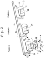
- Figure 2 shows a schematic perspective view a conveyor 5 for vehicle doors 2, the direction arrow C are moved.
- a first assembly position Position a
- the window lifter 3 In a first assembly position (Position a) the window lifter 3 is in the door body 20 used and with the inner or a carrier plate the vehicle door 2 connected.
- the vehicle door 2 After installing the window regulator 3 in the door body 20 the vehicle door 2 is in position b by means of a rotating arm 51 according to the arrow E through 180 ° Longitudinal axis of the vehicle door 2 rotated so that the Lower edge 22 of the vehicle door 2 above the upper edge 21 located.
- a rotating arm 51 according to the arrow E through 180 ° Longitudinal axis of the vehicle door 2 rotated so that the Lower edge 22 of the vehicle door 2 above the upper edge 21 located.
- the door body 20 In the "upside down position" the door body 20 is in the following position c above one of several window panes 1 containing magazine 7, which on guide rail 9 9 in the direction of arrow F perpendicular to the conveying direction C of Conveyor 5 is moved so that one in each a "upside-down position" held in the magazine 7 window pane 1 with its lower edge below the upper edge 21, that is, below that in the upper edge 21 of the door body 20 trained slot is arranged.
- the window panes 1 are either in each window pane 1 assigned teaching held within magazine 7 or the magazine 7 is designed so that it is simultaneously Lessons for the window panes 1 arranged therein forms.
- a window pane 1 becomes raised and shifted into the door shaft of the door body 20 until the lower edge 11 of the window pane 1 in the Adjustment and clamping position of the window lifter drivers 3 is added. In this position you can manually the clamping of the window pane 1 in the drivers of Window lifters 3 take place or with an automatic Recording the window pane 1 in the driver of the window regulator 3 blind assembly can be carried out.
- the conveyor 5 by means of a lifting and lowering arm 50 in the direction of arrow D are moved so that the vehicle door 2 to the adjustment and Clamping position is approximated.
- both lifting devices possible, so that both the window pane 1 is raised by means of the lifting device 8 as well as the relevant vehicle door 2 by means of Lifting and lowering arm 50 is lowered.
- the window panes 1 are in the magazine 7 in the "Upside down position" in which they are immediately before assembly be brought by a mechanic who is the window panes in an apprenticeship with preferably three support points uses so that the window panes 1 in the mounting direction be aligned.
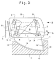
- Figure 3 illustrates the "upside down assembly” in a schematic Representation and shows that by means of the rotary arm 51st the conveyor 5 held in the "upside down position" Vehicle door 2, so that in the mounting position on the vehicle upper edge 21 of the door body 20 below the lower edge 22 of the door body 20 is arranged.
- the one with the window body 3 connected window lifters 3 with the in Guide rails 31, 32 guided drivers 33, 34 and Deflection rollers 35 to 38, a window lift drive 30 and a window regulator cable 39 is located with the door body 20 also in the "upside down position".
- the window pane 1 is used in a teaching 6 that is designed so that the upper edge due to gravity 12 and at least one of the side edges 13, 14 on contact edges or points 61 to 63 of teaching 6 and so on align the window pane 1 in a predetermined position. In this position, the window pane 1 in the Teach 6 held until the vehicle door 2 a target position has reached in the vehicle shaft in the door body 20 is aligned with the window pane 1.
- the window regulator 3 located drivers 33, 34 reduced up in the Adjustment and clamping position A the attachment points 15, 16 the window pane 1 non-positively and / or positively to the Carriers 33, 34 of the window regulator 3 can be set.
- the window regulator 3 can then be moved to position B be moved so that the window pane 1 in the dashed position. In this position the Window pane 1 lifted out of gauge 6, which then by means of the lifting device shown in Figure 2 8 can be returned to the starting position.
- the window can be clamped firmly 1, that is, the connection of the fastening points 15, 16 of the window pane 1 with the drivers 33, 34 one Undergo review. Since the window pane 1 located below the vehicle door 2 would be an insufficient one Clamping the window pane 1 in the drivers 33, 34 when approaching position B to loosen the fastening points 15, 16 from the carriers 33, 34 due to the Effect gravity and the window pane 1 in teaching 6 remain.
Landscapes
- Engineering & Computer Science (AREA)
- Manufacturing & Machinery (AREA)
- Chemical & Material Sciences (AREA)
- Combustion & Propulsion (AREA)
- Transportation (AREA)
- Mechanical Engineering (AREA)
- Automobile Manufacture Line, Endless Track Vehicle, Trailer (AREA)
- Automatic Assembly (AREA)
- Window Of Vehicle (AREA)
Applications Claiming Priority (2)
| Application Number | Priority Date | Filing Date | Title |
|---|---|---|---|
| DE19836077 | 1998-07-30 | ||
| DE19836077A DE19836077C2 (de) | 1998-07-30 | 1998-07-30 | Vorrichtung zum Verbinden einer Fensterscheibe mit einem Fensterheber |
Publications (3)
| Publication Number | Publication Date |
|---|---|
| EP0976646A2 true EP0976646A2 (fr) | 2000-02-02 |
| EP0976646A3 EP0976646A3 (fr) | 2001-10-04 |
| EP0976646B1 EP0976646B1 (fr) | 2003-09-24 |
Family
ID=7877005
Family Applications (1)
| Application Number | Title | Priority Date | Filing Date |
|---|---|---|---|
| EP99250244A Expired - Lifetime EP0976646B1 (fr) | 1998-07-30 | 1999-07-22 | Méthode et dispositif pour fixer un panneau de fenêtre avec un lève-vitre |
Country Status (4)
| Country | Link |
|---|---|
| US (1) | US6247218B1 (fr) |
| EP (1) | EP0976646B1 (fr) |
| DE (2) | DE19836077C2 (fr) |
| ES (1) | ES2209328T3 (fr) |
Families Citing this family (4)
| Publication number | Priority date | Publication date | Assignee | Title |
|---|---|---|---|---|
| DE50110269D1 (de) * | 2001-07-05 | 2006-08-03 | Ford Global Tech Llc | Verfahren und Vorrichtung zur Herstellung einer Tür oder Klappe |
| FR2875211B1 (fr) * | 2004-09-15 | 2006-12-22 | Peugeot Citroen Automobiles Sa | Dispositif et procede d'assistance a la fixation d'un element de vitrage a une porte sans cadre d'un vehicule automobile |
| EP1935558A1 (fr) * | 2006-12-19 | 2008-06-25 | Pilkington Italia S.p.A. | Procédé et système de fabrication de fenêtres sans cadre |
| EP1936088A1 (fr) * | 2006-12-19 | 2008-06-25 | Pilkington Italia S.p.A. | Fenêtre sans cadre et son procédé de fabrication |
Family Cites Families (13)
| Publication number | Priority date | Publication date | Assignee | Title |
|---|---|---|---|---|
| US3858381A (en) * | 1973-07-18 | 1975-01-07 | Xerox Corp | Envelope stuffing apparatus |
| US4295262A (en) * | 1980-03-21 | 1981-10-20 | Thermoplastics, Inc. | Method of making truck bed cover assembly |
| US4609093A (en) * | 1985-06-28 | 1986-09-02 | Mazda Motor Corporation | Hanger conveyance in automobile assembly line |
| JPS62247260A (ja) * | 1986-04-19 | 1987-10-28 | Fuji Photo Film Co Ltd | 分析用スライド装填装置 |
| US4716682A (en) * | 1986-08-06 | 1988-01-05 | American Motors Corporation | Modular door structure |
| DE3782216T2 (de) * | 1986-08-25 | 1993-02-25 | Mazda Motor | Fahrzeugtueraufbau und verfahren zu ihrem zusammenbau. |
| US5121534A (en) * | 1990-07-30 | 1992-06-16 | Ford Motor Company | Method of assembling a unitized window system for a vehicle door |
| JP2765297B2 (ja) * | 1991-10-03 | 1998-06-11 | 株式会社ダイフク | ドア搬送設備 |
| JPH06227460A (ja) * | 1993-01-30 | 1994-08-16 | Mazda Motor Corp | 車両ドアの組立装置 |
| US5507085A (en) * | 1993-05-13 | 1996-04-16 | Cybex Technologies Corp. | Method and apparatus for automatically placing lids on component packages |
| US5348147A (en) * | 1993-09-08 | 1994-09-20 | Moore Business Forms, Inc. | Carton for bulk pack cut single paper |
| US5621960A (en) * | 1994-04-15 | 1997-04-22 | Owens-Illinois Plastic Products Inc. | Method and apparatus for forming an assembly of a flexible tube and closure |
| JPH09207845A (ja) * | 1996-01-31 | 1997-08-12 | Mazda Motor Corp | ドアガラスの位置決め方法および装置 |
-
1998
- 1998-07-30 DE DE19836077A patent/DE19836077C2/de not_active Expired - Fee Related
-
1999
- 1999-07-22 EP EP99250244A patent/EP0976646B1/fr not_active Expired - Lifetime
- 1999-07-22 DE DE59907090T patent/DE59907090D1/de not_active Expired - Fee Related
- 1999-07-22 ES ES99250244T patent/ES2209328T3/es not_active Expired - Lifetime
- 1999-07-29 US US09/363,537 patent/US6247218B1/en not_active Expired - Fee Related
Non-Patent Citations (1)
| Title |
|---|
| None |
Also Published As
| Publication number | Publication date |
|---|---|
| DE19836077C2 (de) | 2000-05-31 |
| DE59907090D1 (de) | 2003-10-30 |
| US6247218B1 (en) | 2001-06-19 |
| EP0976646B1 (fr) | 2003-09-24 |
| DE19836077A1 (de) | 2000-02-10 |
| EP0976646A3 (fr) | 2001-10-04 |
| ES2209328T3 (es) | 2004-06-16 |
Similar Documents
| Publication | Publication Date | Title |
|---|---|---|
| EP1340878B1 (fr) | Lève-vitre à câble pour manoeuvrer des vitres à courbure sphérique | |
| EP0999974B1 (fr) | Procede de pose de charnieres de portiere sur des carrosseries de vehicule et dispositif pour executer ce procede | |
| EP0593719A1 (fr) | Procede et dispositif de montage de portieres dans des carrosseries d'automobiles | |
| DE19650265C1 (de) | Vorrichtung zum Verbinden eines Armfensterhebers mit der verschiebbaren Fensterscheibe eines Kraftfahrzeugs | |
| EP3687934A1 (fr) | Dispositif d'alignement et procédé de montage d'un rail de guidage dans une cage d'ascenseur d'une installation d'ascenseur | |
| EP0147530A2 (fr) | Procédé pour positionner et fixer un corps plan dans l'espace à au moins un autre corps et dispositif pour la mise en oeuvre du procédé | |
| DE102009037215A1 (de) | Verfahren zur Dichtungsapplikation an Bauteilen und Anlage zur Durchführung des Verfahrens | |
| DE102009034276A1 (de) | Vorrichtung zur Ausrichtung von Kfz-Türen auf der Schlossseite | |
| EP0109621A2 (fr) | Dispositif de fixation d'une vitre de véhicule automobile | |
| EP0226212B1 (fr) | Dispositif et procédé pour le montage par en dessous des groupes de propulsion dans une carrosserie automobile | |
| DE102011110168B4 (de) | Anordnung zur Befestigung einer Fensterscheibe an einem Fensterheber eines Fahrzeugs sowie Scheibenhalter dazu. | |
| EP0976646B1 (fr) | Méthode et dispositif pour fixer un panneau de fenêtre avec un lève-vitre | |
| EP1341642B1 (fr) | Procédé et dispositif pour assembler une portière de véhicule | |
| DE4140574A1 (de) | Selbstzentrierende verbindung zur montage einer vorjustierten funktionseinheit | |
| DE102009008725A1 (de) | Vorrichtung und Verfahren zum Anbringen wenigstens eines Zierelementes an eine Fahrzeugtür oder an einen Kotflügel eines Fahrzeuges | |
| EP0939704B1 (fr) | Procede et dispositif pour le montage des profiles d'etancheite sur le bord d'une ouverture | |
| DE19860555A1 (de) | Verfahren und Montagevorrichtung zur positionsgenauen Montage von Fahrzeugfenstern | |
| DE102008047810A1 (de) | Vorrichtung zum Befestigen von elektrischen, auch vorkonfektionierten Anschlussteilen wie Lötfahnen, Lötkante, Steckverbinder oder dergleichen Elemente | |
| EP0384019B1 (fr) | Compensateur de jeu d'un dispositif d'entraînement | |
| DE60109832T2 (de) | Einrichtung für die Positionierung eines stark gewölbten Teiles in einer vorbestimmten Stellung und Verfahren angewendet auf diese Einrichtung | |
| DE4102941A1 (de) | Vorrichtung zum hoehenverlagern einer fahrzeugfensterscheibe | |
| DE10036628A1 (de) | Vorrichtung zur Montage von Ecklagern und Beschlägen an einen Blendrahmen | |
| EP1617028B1 (fr) | Lève-vitre pour une porte de véhicule | |
| DE4106958C2 (fr) | ||
| DE4233267C2 (de) | Verfahren zum Einstellen einer rahmenlosen in eine Fahrzeugtür absenkbaren Seitenscheibe |
Legal Events
| Date | Code | Title | Description |
|---|---|---|---|
| PUAI | Public reference made under article 153(3) epc to a published international application that has entered the european phase |
Free format text: ORIGINAL CODE: 0009012 |
|
| AK | Designated contracting states |
Kind code of ref document: A2 Designated state(s): AT BE CH CY DE DK ES FI FR GB GR IE IT LI LU MC NL PT SE Kind code of ref document: A2 Designated state(s): DE ES FR GB IT SE |
|
| AX | Request for extension of the european patent |
Free format text: AL;LT;LV;MK;RO;SI |
|
| PUAL | Search report despatched |
Free format text: ORIGINAL CODE: 0009013 |
|
| AK | Designated contracting states |
Kind code of ref document: A3 Designated state(s): AT BE CH CY DE DK ES FI FR GB GR IE IT LI LU MC NL PT SE |
|
| AX | Request for extension of the european patent |
Free format text: AL;LT;LV;MK;RO;SI |
|
| 17P | Request for examination filed |
Effective date: 20010907 |
|
| AKX | Designation fees paid |
Free format text: DE ES FR GB IT SE |
|
| GRAH | Despatch of communication of intention to grant a patent |
Free format text: ORIGINAL CODE: EPIDOS IGRA |
|
| RIN1 | Information on inventor provided before grant (corrected) |
Inventor name: STRAENG, JOERGEN Inventor name: SAUNUS, CHRISTIAN, DIPL.-ING. |
|
| GRAS | Grant fee paid |
Free format text: ORIGINAL CODE: EPIDOSNIGR3 |
|
| GRAA | (expected) grant |
Free format text: ORIGINAL CODE: 0009210 |
|
| AK | Designated contracting states |
Kind code of ref document: B1 Designated state(s): DE ES FR GB IT SE |
|
| REG | Reference to a national code |
Ref country code: GB Ref legal event code: FG4D Free format text: NOT ENGLISH |
|
| REF | Corresponds to: |
Ref document number: 59907090 Country of ref document: DE Date of ref document: 20031030 Kind code of ref document: P |
|
| PG25 | Lapsed in a contracting state [announced via postgrant information from national office to epo] |
Ref country code: SE Free format text: LAPSE BECAUSE OF FAILURE TO SUBMIT A TRANSLATION OF THE DESCRIPTION OR TO PAY THE FEE WITHIN THE PRESCRIBED TIME-LIMIT Effective date: 20031224 |
|
| GBT | Gb: translation of ep patent filed (gb section 77(6)(a)/1977) |
Effective date: 20040109 |
|
| REG | Reference to a national code |
Ref country code: ES Ref legal event code: FG2A Ref document number: 2209328 Country of ref document: ES Kind code of ref document: T3 |
|
| ET | Fr: translation filed | ||
| PLBE | No opposition filed within time limit |
Free format text: ORIGINAL CODE: 0009261 |
|
| STAA | Information on the status of an ep patent application or granted ep patent |
Free format text: STATUS: NO OPPOSITION FILED WITHIN TIME LIMIT |
|
| 26N | No opposition filed |
Effective date: 20040625 |
|
| PGFP | Annual fee paid to national office [announced via postgrant information from national office to epo] |
Ref country code: FR Payment date: 20050708 Year of fee payment: 7 |
|
| PGFP | Annual fee paid to national office [announced via postgrant information from national office to epo] |
Ref country code: GB Payment date: 20050720 Year of fee payment: 7 |
|
| PG25 | Lapsed in a contracting state [announced via postgrant information from national office to epo] |
Ref country code: IT Free format text: LAPSE BECAUSE OF NON-PAYMENT OF DUE FEES;WARNING: LAPSES OF ITALIAN PATENTS WITH EFFECTIVE DATE BEFORE 2007 MAY HAVE OCCURRED AT ANY TIME BEFORE 2007. THE CORRECT EFFECTIVE DATE MAY BE DIFFERENT FROM THE ONE RECORDED. Effective date: 20050722 |
|
| PGFP | Annual fee paid to national office [announced via postgrant information from national office to epo] |
Ref country code: ES Payment date: 20050818 Year of fee payment: 7 |
|
| PG25 | Lapsed in a contracting state [announced via postgrant information from national office to epo] |
Ref country code: GB Free format text: LAPSE BECAUSE OF NON-PAYMENT OF DUE FEES Effective date: 20060722 |
|
| PGFP | Annual fee paid to national office [announced via postgrant information from national office to epo] |
Ref country code: DE Payment date: 20060731 Year of fee payment: 8 |
|
| GBPC | Gb: european patent ceased through non-payment of renewal fee |
Effective date: 20060722 |
|
| REG | Reference to a national code |
Ref country code: FR Ref legal event code: ST Effective date: 20070330 |
|
| REG | Reference to a national code |
Ref country code: ES Ref legal event code: FD2A Effective date: 20060724 |
|
| PG25 | Lapsed in a contracting state [announced via postgrant information from national office to epo] |
Ref country code: ES Free format text: LAPSE BECAUSE OF NON-PAYMENT OF DUE FEES Effective date: 20060724 |
|
| PG25 | Lapsed in a contracting state [announced via postgrant information from national office to epo] |
Ref country code: FR Free format text: LAPSE BECAUSE OF NON-PAYMENT OF DUE FEES Effective date: 20060731 Ref country code: DE Free format text: LAPSE BECAUSE OF NON-PAYMENT OF DUE FEES Effective date: 20080201 |