EP0976668A2 - Scharnierbandkette - Google Patents
Scharnierbandkette Download PDFInfo
- Publication number
- EP0976668A2 EP0976668A2 EP99114841A EP99114841A EP0976668A2 EP 0976668 A2 EP0976668 A2 EP 0976668A2 EP 99114841 A EP99114841 A EP 99114841A EP 99114841 A EP99114841 A EP 99114841A EP 0976668 A2 EP0976668 A2 EP 0976668A2
- Authority
- EP
- European Patent Office
- Prior art keywords
- slat
- conveyor chain
- slat conveyor
- drain holes
- treatment liquid
- Prior art date
- Legal status (The legal status is an assumption and is not a legal conclusion. Google has not performed a legal analysis and makes no representation as to the accuracy of the status listed.)
- Granted
Links
Images




Classifications
-
- B—PERFORMING OPERATIONS; TRANSPORTING
- B65—CONVEYING; PACKING; STORING; HANDLING THIN OR FILAMENTARY MATERIAL
- B65G—TRANSPORT OR STORAGE DEVICES, e.g. CONVEYORS FOR LOADING OR TIPPING, SHOP CONVEYOR SYSTEMS OR PNEUMATIC TUBE CONVEYORS
- B65G17/00—Conveyors having an endless traction element, e.g. a chain, transmitting movement to a continuous or substantially-continuous load-carrying surface or to a series of individual load-carriers; Endless-chain conveyors in which the chains form the load-carrying surface
- B65G17/30—Details; Auxiliary devices
- B65G17/38—Chains or like traction elements; Connections between traction elements and load-carriers
-
- B—PERFORMING OPERATIONS; TRANSPORTING
- B65—CONVEYING; PACKING; STORING; HANDLING THIN OR FILAMENTARY MATERIAL
- B65G—TRANSPORT OR STORAGE DEVICES, e.g. CONVEYORS FOR LOADING OR TIPPING, SHOP CONVEYOR SYSTEMS OR PNEUMATIC TUBE CONVEYORS
- B65G17/00—Conveyors having an endless traction element, e.g. a chain, transmitting movement to a continuous or substantially-continuous load-carrying surface or to a series of individual load-carriers; Endless-chain conveyors in which the chains form the load-carrying surface
- B65G17/06—Conveyors having an endless traction element, e.g. a chain, transmitting movement to a continuous or substantially-continuous load-carrying surface or to a series of individual load-carriers; Endless-chain conveyors in which the chains form the load-carrying surface having a load-carrying surface formed by a series of interconnected, e.g. longitudinal, links, plates, or platforms
- B65G17/08—Conveyors having an endless traction element, e.g. a chain, transmitting movement to a continuous or substantially-continuous load-carrying surface or to a series of individual load-carriers; Endless-chain conveyors in which the chains form the load-carrying surface having a load-carrying surface formed by a series of interconnected, e.g. longitudinal, links, plates, or platforms the surface being formed by the traction element
-
- B—PERFORMING OPERATIONS; TRANSPORTING
- B65—CONVEYING; PACKING; STORING; HANDLING THIN OR FILAMENTARY MATERIAL
- B65G—TRANSPORT OR STORAGE DEVICES, e.g. CONVEYORS FOR LOADING OR TIPPING, SHOP CONVEYOR SYSTEMS OR PNEUMATIC TUBE CONVEYORS
- B65G45/00—Lubricating, cleaning, or clearing devices
- B65G45/02—Lubricating devices
-
- B—PERFORMING OPERATIONS; TRANSPORTING
- B65—CONVEYING; PACKING; STORING; HANDLING THIN OR FILAMENTARY MATERIAL
- B65G—TRANSPORT OR STORAGE DEVICES, e.g. CONVEYORS FOR LOADING OR TIPPING, SHOP CONVEYOR SYSTEMS OR PNEUMATIC TUBE CONVEYORS
- B65G2201/00—Indexing codes relating to handling devices, e.g. conveyors, characterised by the type of product or load being conveyed or handled
- B65G2201/02—Articles
Definitions
- the present invention relates generally to a slat conveyor chain for conveying articles while a treatment liquid such as soap-and-water solution is supplied onto the load-bearing upper surface of the slat conveyor chain. More particularly, this invention relates to such a slat conveyor chain which is particularly suitable for conveyance of PET (polyethylene terephthalate) bottles, cans or the like containers for medicines and beverages.
- PET polyethylene terephthalate
- a slat conveyor chain formed from synthetic resin is used for conveyance of PET bottles, cans or the like containers for medicines and beverages.
- the conventional synthetic resin slat conveyor chain includes a series of slats 1 and chain links 2 formed integrally with respective undersides of the slats 1 and articulated by pins 3 at their reinforcement ribs to form an endless chain.
- the slats 1 are made from an engineering plastics such as polyacetal resin.
- the pins 3 are formed from stainless steel or engineering plastics.
- the conventional slot conveyor chain is looped around a pair of horizontally spaced drive and driven sprockets S1, 52 and is driven by the drive sprocket 1 to transport articles W such as beverage containers carried on respective load-bearing upper surfaces of the slats 1 while respective undersides of the slats 1 are stably guided by a pair of laterally spaced guide rails R, R ( Figure 9) located on opposite sides of the links 3.
- a soap-and-water solution is showered from a nozzle N onto the load-bearing upper surfaces of the slats 1 to lower the friction coefficient of the load-bearing upper surfaces and to lubricate the chain.
- the nozzle N is disposed above the slat conveyor chain at a position near the driven sprocket S2, as shown in Figure 10.
- the PET bottles for which demand has increased in recent years, are relatively soft. Accordingly, when many such relatively soft PET bottles are accumulated on the synthetic resin slat conveyor chain during conveyance, the accumulated PET bottles are likely to deformed or otherwise damaged due to a large line pressure (conveyance resistance) resulting from an increased frictional resistance produced between the load) bearing upper surfaces of the slats 1 and bottom surfaces of the PET bottles.
- Excessive soap-and-water solution which may stay on the load-bearing upper surfaces of the slats or between the undersides of the slats and the guide rails, scatters around a conveyor frame and thus causes contamination of working environment around the conveyor frame. Additionally, the scattered soap-and-water solution may cause corrosion of bearings fitted around drive and drive shafts of a chain drive mechanism and corrosion of a speed reducer of the chain drive unit, resulting in considerable shortening of the service life of the chain drive mechanism. These problems also occur when the articles to be conveyed are bins or when vast amounts of washing liquid are used for washing articles while being conveyed.
- the present invention seeks to provide a slat chain conveyor which can smoothly discharge an excess amount of treatment liquid, such as lubricating liquid or washing liquid, from an upper surface to the underside of each slat to secure smooth and stable conveyance of articles while keeping the surrounding working environment against contamination with the treatment liquid and also preventing reduction of service life of a chain drive unit due to corrosion of parts with the treatment liquid.
- treatment liquid such as lubricating liquid or washing liquid
- a slat conveyor chain for a slat conveyor including a sprocket for driving the slat conveyor chain to travel in a direction along a guide rail of the slat conveyor for conveyance of articles while a treatment liquid is supplied onto an upper surface of the slat conveyor chain
- the slat conveyor chain comprising: a series of slats each having a multiplicity of drain holes extending from an upper surface to an underside of each slat for the passage therethrough of the treatment liquid, the drain holes being distributed in a desired pattern; a series of links formed integrally with the respective undersides of the slats and articulately connected together by pins to form a flexible endless chain driven by the sprocket; and the underside of the slats each having a sliding surface portion facing the guide rail, and at least one discharge groove formed in the sliding surface portion and connected to at least one of the drain holes for discharging the treatment liquid from the upper surface of each s
- the treatment liquid supplied onto the upper surface of the slat conveyor chain for smooth and damage-free conveyance of the articles is smoothly discharged from the discharging groove through said at least one drain hole without scatting around a frame of the slat conveyor.
- This discharging of the treatment liquid bearings and a speed reducer of a chain drive mechanism are protected against corrosion.
- the slat conveyor chain can, therefore, operate smoothly over a long period of use while keeping the surrounding working environment against contamination with the treatment liquid.
- the drain holes each have a flared end opening at the upper surface of each slat, so that the excessive treatment liquid is smoothly introduced into the drain holes.
- the discharge groove may extend in a direction parallel to the direction of travel of the slat conveyor chain.
- the pattern of the drain holes is preferably such that a plurality of drain holes arranged in a row in a direction parallel to the direction of travel of the slat conveyor chain are all connected to the discharge groove.
- the discharge groove may extend obliquely from the vicinity of an outer side edge of each slat to the associated link in a direction opposite to the direction of travel of the slat conveyor chain.
- the obliquely extending discharge groove is particularly suitable when the treatment liquid is a lubricating liquid because a pin-joint portion between two adjacent links can be lubricated with the lubricating liquid.
- the pattern of the drain holes is preferably such that a plurality of drain holes arranged in a row oblique to the direction of travel of the slat conveyor chain are all connected to the discharge groove.
- each slat is partly spaced by a distance from the guide rail at a leading end portion and a trailing end portion of each slat.
- This arrangement achieves smooth delivery of the treatment liquid from the discharge groove in one slat to the discharge groove in a subsequent slat without causing spouting of the treatment liquid over the upper surface of the slat conveyor chain through a joint clearance between the adjacent slats.
- the distance between the sliding surface portion and the guide rail is preferably at lest equal to a depth of the discharge groove.
- the leading end portion and the trailing end portion are complemental in shape, and the trailing end portion of the one slat is interdigitated with the leading end portion of the subsequent slat.
- FIG 1 shows the general arrangement of a slat conveyor 50 used for conveyance of beverage cans W.
- the slat conveyor 50 includes a slat conveyor chain 60 according to the present invention.
- the slat conveyor chain 60 is an endless chain looped around a pair of horizontally spaced driven and driven sprockets S1 and S2.
- the drive sprocket S1 the slat conveyor chain 60 is driven to travel in a direction indicated by the arrow while an upper run of the slat conveyor chain 60 is guided on and along a pair of parallel spaced horizontal rails R extending between the drive and driven sprockets S1, S2.
- the lower free run of the slat conveyor chain 60 is guided by a plurality of guide rollers (not designated).
- a lubricating liquid such as soap-and-water solution is showered from a nozzle N onto the upper surface of the slat conveyor chain 60.
- the nozzle N is disposed above the slat conveyor chain 60 at a position located near the driven sprocket S2.
- the slat conveyor chain 60 is comprised of a series of slats 10, and a series of links 20 each formed integrally with the underside of one of the slats 10 at a central portion of each slat 10.
- the slat 10 and the link 20 in each pair are integrally molded of synthetic resin such as polyacetal resin.
- the adjacent links 20 are articulately connected by pins 30 ( Figures 2 and 5) and thus form a flexible endless slat conveyor chain 60.
- the slat conveyor chain 60 can be used in a production line for achieving various processing operations, such as processing, washing, sorting, inspection and so on, while the articles are transported on the slat conveyor chain 60..
- the slats 10, links 20 and pins 30 may be formed from engineering plastic materials including polyamide, polybutylene terephthalate, polyacetal, polypropylene and polyethylene.
- polyacetal resins are preferable because they have low friction coefficient, high wear resistance and high electric conductivity.
- super engineering plastics are preferable as a material for the slats 10 and links 20.
- the slats 10 each have a multiplicity of drain holes 11 extending from an upper surface 10a to the underside 10b of each slat 10. As shown in Figure 2A, one end lla of each drain hole 11, which opens at the upper surface 10a of the slat 10, is countersunk or flared to guide the lubricating liquid smoothly into the drain hole 11.
- the drain holes 11 are distributed in a desired pattern substantially over the entire area of the slat 10, as shown in Figure 3.
- the upper surfaces 10a of the slats 10 form the load-bearing upper surface of the slat conveyor chain 60 on which the beverage cans (articles) W are carried.
- each slat 10 has a pair of laterally spaced sliding surface portions 13 disposed on opposite sides of the link 20 and facing the guide rails R, R of the slat conveyor, respectively, as shown in Figure 4.
- Each of the sliding surface portions 13 has a plurality (two in the illustrated embodiment) of discharge grooves 12 extending linearly from a leading end (left end in Figure 5) to a trailing end (right end in Figure 5) of the slat 10 in a direction parallel to the direction of chain travel indicated by the profiled arrow shown in Figure 5.
- Each of the discharge grooves 12 is connected to a plurality (three in the illustrated embodiment) of drain holes 11 arranged in a row extending in a direction parallel to the direction of chain travel.
- the lubricating liquid supplied onto the upper surface 10a of the slat 10 is discharged from the discharge grooves 12 through the drain holes 11. Since the discharged grooves 12 are arranged parallel to the direction of chain travel, the lubricating liquid is discharged in a direction opposite to the direction of chain travel without scattering around a frame of the slat conveyor 50 ( Figure 1).
- the lubricating liquid (soap-and-water solution) is supplied from the nozzle N ( Figure 1) onto the upper surface of the slat conveyor chain 60 during operation of the slat conveyor 50 ( Figure 1).
- An excess amount of lubricating liquid which would otherwise tend to stay on the upper surfaces 10a of the slats 10, is smoothly introduced into the drain holes 11 via the flared ends 11a, then discharged from the discharged grooves 12 in a direction opposite to the direction of chain travel. Since the excessive lubricating liquid is removed from the load-bearing upper surfaces 10a of the slats 10 without scatting around the conveyor frame, the working environment around the slat conveyor 50 ( Figure 1) is kept free from contamination with the lubricating liquid.
- the chain drive mechanism since the lubricating liquid does not cause corrosion of bearings (not shown) of a chain drive mechanism including the sprockets S1, S2, nor does it enter a speed reducer (not shown) of the chain drive mechanism, the chain drive mechanism has a long service life and can operate reliably throughout such long service life.
- FIG. 6 shows the underside of part of a slat conveyor chain 70 according to another embodiment of the present invention.
- the slat conveyor chain 70 is substantially the same in construction as the slat conveyor chain 60 of the foregoing embodiment shown in Figure 5 with the exception that discharge grooves 12' formed in each sliding surface portion 13 of one slat 11' extend obliquely from the vicinity of an outer side edge of the slat 11' toward a longitudinal centerline of the slat conveyor chain 70 (on which the link 20 is located) in a direction opposite to the direction of chain travel indicated by the profiled arrow shown in Figure 6.
- the discharge grooves 12' extend at an angle to the longitudinal centerline of the slat conveyor chain 70 such that they converge in the opposite direction to the chain travel.
- Each of the discharge grooves 12' is connected to a plurality of drain holes 11 arranged in a row extending obliquely to the longitudinal centerline of the slat conveyor chain 70.
- the lubricating liquid supplied onto an upper surface of the slat conveyor chain 70 is introduced into the drain holes 11 and subsequently discharged from the discharge grooves 12' in a direction opposite to the direction of chain travel.
- the discharge grooves 12' are converging toward the longitudinal centerline of the slat conveyor chain 70, the lubricating liquid is positively guided toward a central portion of each slat 10' and thus can be used for lubricating a joint portion between each pair of adjacent links 20, 20.
- This centralized discharging of the treatment liquid it becomes possible to recover the lubricating liquid through a filtering unit and then use the recovered lubricating liquid again through a recirculating passage. This may achieve considerable saving of resources and energy used in the production line.
- Figure 7 shows a modification according to the present invention. This modification can be incorporated in the slats 10, 10' described previously with reference to Figures 5 and 6, respectively.
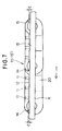
- the sliding surface portions 13 (one being shown) of the slat 10 (10') are spaced from the corresponding guide rails R by a distance C at both leading and trailing end portions 14, 15 of the slat 10 (10').
- the distance C is preferably at least equal to the depth of the discharge grooves 12.
- each slat 10 (10') has a recessed profile complemental to a recessed profile of the trailing end portion 15 of an adjacent slat 10 (10'), so that when two adjacent slats 10 (10') are joined together by the pin 30, the recessed trailing end portion 14 of one slat 10 (10') is interdigitated with the recessed leading end portion 15 of the other slat 10 (10').
- each slat 10 (10') are spaced from the guide rails R by the distance C at the leading and trailing end portions 14, 15 of the slat 10 (19')
- a lubricating liquid is supplied from the nozzle N ( Figure 1) onto the upper surface of the slat conveyor chain 60 (70)
- an excess amount of lubricating liquid discharged from the discharge grooves 12 in one slat 10 (10') is smoothly delivered into the discharge groove 12 in a subsequent slat 10 (10') without spouting over the upper surface of the subsequent slat 10 through a joint clearance between the two adjacent slats 10 (10').
- the frictional resistance between the sliding surface portions 13 of the slats 10 (10') and the guide rails R is considerably decreased and thus insures smooth traveling of the slat conveyor chain.
Landscapes
- Engineering & Computer Science (AREA)
- Mechanical Engineering (AREA)
- Chain Conveyers (AREA)
Applications Claiming Priority (2)
| Application Number | Priority Date | Filing Date | Title |
|---|---|---|---|
| JP21458398A JP3448220B2 (ja) | 1998-07-29 | 1998-07-29 | スラットコンベヤチェーン |
| JP21458398 | 1998-07-29 |
Publications (3)
| Publication Number | Publication Date |
|---|---|
| EP0976668A2 true EP0976668A2 (de) | 2000-02-02 |
| EP0976668A3 EP0976668A3 (de) | 2001-04-18 |
| EP0976668B1 EP0976668B1 (de) | 2003-06-11 |
Family
ID=16658129
Family Applications (1)
| Application Number | Title | Priority Date | Filing Date |
|---|---|---|---|
| EP99114841A Expired - Lifetime EP0976668B1 (de) | 1998-07-29 | 1999-07-29 | Scharnierbandkette |
Country Status (7)
| Country | Link |
|---|---|
| US (1) | US6189686B1 (de) |
| EP (1) | EP0976668B1 (de) |
| JP (1) | JP3448220B2 (de) |
| KR (1) | KR100429038B1 (de) |
| CN (1) | CN1116211C (de) |
| DE (1) | DE69908715T2 (de) |
| TW (1) | TW473447B (de) |
Cited By (9)
| Publication number | Priority date | Publication date | Assignee | Title |
|---|---|---|---|---|
| DE10033499A1 (de) * | 2000-07-05 | 2002-01-24 | Univ Dresden Tech | Fördergurt aus Elementen sowie Element hierfür |
| EP1790592A1 (de) * | 2005-11-25 | 2007-05-30 | Sunbird Investments Limited | Förderer und Schmierverfahren für ein Förderband |
| WO2007090312A1 (en) * | 2006-02-09 | 2007-08-16 | Habasit Ag | .module for a perforated flat top belt with hinge gap for better fluid flow |
| NL2004492C2 (nl) * | 2010-03-31 | 2011-10-04 | Rexnord Flattop Europe Bv | Transporteur. |
| WO2012068699A1 (de) * | 2010-11-26 | 2012-05-31 | Ferag Ag | Plattenelement eines förderers zum ausbilden einer zusammengesetzten förderfläche |
| WO2012001538A3 (en) * | 2010-06-29 | 2012-07-19 | Pulsar S.R.L. | A conveyor with articulated links |
| CN104129602A (zh) * | 2014-07-24 | 2014-11-05 | 江苏永钢集团有限公司 | 改进型移钢链的链条传动装置 |
| CN108001948A (zh) * | 2017-12-05 | 2018-05-08 | 宜都中起重工机械有限公司 | 一种废钢鳞板输送机、输送方法及应用 |
| EP4458736A1 (de) * | 2023-05-05 | 2024-11-06 | Robert Bosch GmbH | Kettenglied für eine kurvengängige förderkette, kurvengängige förderkette und transfersystem mit kurvengängiger förderkette |
Families Citing this family (32)
| Publication number | Priority date | Publication date | Assignee | Title |
|---|---|---|---|---|
| JP3448220B2 (ja) * | 1998-07-29 | 2003-09-22 | 株式会社椿本チエイン | スラットコンベヤチェーン |
| US6382405B1 (en) * | 2000-02-25 | 2002-05-07 | Kvp Plastic Belting, Inc. | Solid top radius conveyor belt |
| JP4010755B2 (ja) * | 2000-08-31 | 2007-11-21 | 株式会社椿本チエイン | コンベヤチェーン |
| ITMI20020586A1 (it) * | 2002-03-20 | 2003-09-22 | Regina Sud Spa | Stampo per maglie di catene di trasporto e maglia |
| US6822207B2 (en) * | 2002-04-19 | 2004-11-23 | Richard F. Schmidt | Continuous product conveyor having a brick baking hearth |
| JP3616625B2 (ja) * | 2002-10-03 | 2005-02-02 | 株式会社椿本チエイン | コンベヤチェーン |
| DE102004021262A1 (de) | 2004-04-30 | 2005-11-17 | Sander Hansen A/S | Pasteur mit Förderband |
| JP4173151B2 (ja) * | 2005-05-23 | 2008-10-29 | 株式会社椿本チエイン | コンベヤチェーン |
| US7360643B1 (en) * | 2007-03-20 | 2008-04-22 | Habasit Ag | Electroconductive modular belt |
| EP2105494B1 (de) * | 2008-03-25 | 2019-05-08 | Diversey, Inc. | Verfahren zum Schmieren eines Förderbands |
| US20120018281A1 (en) * | 2010-07-21 | 2012-01-26 | Mccormick Stephen A | Conveyor belt with articulating transport surface |
| CN102491615A (zh) * | 2011-11-29 | 2012-06-13 | 钱尧翎 | 一种烟气污泥烘干机链板输送机构 |
| JP2014118281A (ja) * | 2012-12-18 | 2014-06-30 | Tsubakimoto Chain Co | チェーン搬送装置 |
| WO2014124489A1 (en) * | 2013-02-13 | 2014-08-21 | Pspt Holdings Pty Ltd | Conveyor support drive system |
| NL2011275C2 (en) * | 2013-08-07 | 2015-02-10 | Rexnord Flattop Europe Bv | A conveyor system, a conveyor and lubricating system, a friction coefficient measuring device and an item base surface friction coefficient measuring device both for use in such a system. |
| MX367836B (es) * | 2013-11-12 | 2019-09-09 | Transnorm System Inc | Tira para un transportador. |
| DE102014118244A1 (de) * | 2014-12-09 | 2016-06-09 | Hauni Maschinenbau Ag | Tragförderkettenglied, Tragförderkette sowie Transfer- und/oder Speichersystem für stabförmige Artikel der Tabak verarbeitenden Industrie |
| ES2594480B1 (es) * | 2015-06-19 | 2017-09-27 | Manufacturas Y Transformados Ab, S.L. | Estructura reticular flexible |
| WO2017145315A1 (ja) * | 2016-02-25 | 2017-08-31 | 株式会社アルス | 搬送コンベヤ |
| CN106276754A (zh) * | 2016-10-28 | 2017-01-04 | 贵州长康农业生态科技有限公司 | 一种灌装红树莓果浆或保健酒的驱动机构 |
| DE102017109451A1 (de) * | 2017-05-03 | 2018-11-08 | Tvi Entwicklung Und Produktion Gmbh | Produkt-Träger, Transportvorrichtung unter Verwendung der Produkt-Träger als Transportschlitten, Betriebs-Verfahren hierfür |
| CN107324858B (zh) * | 2017-07-18 | 2018-11-02 | 金华康扬环境科技有限公司 | 有机固废发酵箱 |
| US10294040B2 (en) * | 2017-07-19 | 2019-05-21 | George W. Massey, Jr. | Split fluid jet head and manifold for receipt of split fluid jet head |
| ES2723748B2 (es) * | 2018-02-23 | 2020-02-28 | Open Mind Ventures S L U | Estructura reticular flexible |
| CN110104379A (zh) * | 2019-04-25 | 2019-08-09 | 深圳市格林晟自动化技术有限公司 | 一种新型爬坡式连续升降机 |
| DE102019116369A1 (de) * | 2019-06-17 | 2020-12-17 | Tsubaki Kabelschlepp GmbH | Leitungsführungseinrichtung mit Vertiefungen |
| CN110686507B (zh) * | 2019-09-29 | 2021-04-30 | 山东嘉和耐火材料有限责任公司 | 一种链板式砖坯连续干燥窑 |
| CN110525882B (zh) * | 2019-10-16 | 2024-09-03 | 江苏华泰重工装备有限公司 | 一种带过滤及干燥功能的管链输送装置 |
| CN110816958B (zh) * | 2019-12-11 | 2025-03-11 | 河南中烟工业有限责任公司 | 用于条烟输送线链板的润滑装置 |
| CN117140366B (zh) * | 2023-10-11 | 2026-01-09 | 山东开泰抛丸机械股份有限公司 | 钢管输送装置和喷砂清理机 |
| CN117416704B (zh) * | 2023-12-04 | 2025-12-09 | 内蒙古日盛民爆集团日昊化工有限公司 | 一种乳化炸药输送防粘连设备 |
| CN118004667A (zh) * | 2024-02-26 | 2024-05-10 | 北京市市政工程设计研究总院有限公司 | 用于垃圾箱的移箱装置、垃圾中转站以及垃圾箱的移箱方法 |
Family Cites Families (7)
| Publication number | Priority date | Publication date | Assignee | Title |
|---|---|---|---|---|
| US1883528A (en) * | 1931-01-17 | 1932-10-18 | Buck Dryer Corp | Conveyer |
| US4394901A (en) * | 1980-12-16 | 1983-07-26 | Ashworth Bros., Inc. | Modular plastic conveyor belt |
| US5253744A (en) * | 1991-03-15 | 1993-10-19 | Hartness International | Accumulator |
| US5213203A (en) * | 1992-06-16 | 1993-05-25 | Kinney D Brooke | Endless conveyor system |
| US5335768A (en) * | 1993-03-12 | 1994-08-09 | Rexnord Corporation | Conveyor chain assembly |
| JP3020869B2 (ja) | 1996-05-31 | 2000-03-15 | 株式会社椿本チエイン | テーブルトップチェーン用支持レール |
| JP3448220B2 (ja) * | 1998-07-29 | 2003-09-22 | 株式会社椿本チエイン | スラットコンベヤチェーン |
-
1998
- 1998-07-29 JP JP21458398A patent/JP3448220B2/ja not_active Expired - Lifetime
-
1999
- 1999-07-26 TW TW088112604A patent/TW473447B/zh not_active IP Right Cessation
- 1999-07-28 CN CN99111670A patent/CN1116211C/zh not_active Expired - Fee Related
- 1999-07-28 KR KR10-1999-0030768A patent/KR100429038B1/ko not_active Expired - Fee Related
- 1999-07-29 US US09/363,428 patent/US6189686B1/en not_active Expired - Fee Related
- 1999-07-29 DE DE69908715T patent/DE69908715T2/de not_active Expired - Fee Related
- 1999-07-29 EP EP99114841A patent/EP0976668B1/de not_active Expired - Lifetime
Cited By (12)
| Publication number | Priority date | Publication date | Assignee | Title |
|---|---|---|---|---|
| DE10033499A1 (de) * | 2000-07-05 | 2002-01-24 | Univ Dresden Tech | Fördergurt aus Elementen sowie Element hierfür |
| EP1790592A1 (de) * | 2005-11-25 | 2007-05-30 | Sunbird Investments Limited | Förderer und Schmierverfahren für ein Förderband |
| US7819236B2 (en) | 2005-11-25 | 2010-10-26 | Sunbird Investments Limited | Conveyor and lubrication process for a conveyor belt of a conveyor for bottles or containers in general |
| WO2007090312A1 (en) * | 2006-02-09 | 2007-08-16 | Habasit Ag | .module for a perforated flat top belt with hinge gap for better fluid flow |
| US7364036B2 (en) | 2006-02-09 | 2008-04-29 | Habasit Ag | Module for a perforated flat top belt with hinge gap for better fluid flow |
| NL2004492C2 (nl) * | 2010-03-31 | 2011-10-04 | Rexnord Flattop Europe Bv | Transporteur. |
| WO2012001538A3 (en) * | 2010-06-29 | 2012-07-19 | Pulsar S.R.L. | A conveyor with articulated links |
| WO2012068699A1 (de) * | 2010-11-26 | 2012-05-31 | Ferag Ag | Plattenelement eines förderers zum ausbilden einer zusammengesetzten förderfläche |
| CN104129602A (zh) * | 2014-07-24 | 2014-11-05 | 江苏永钢集团有限公司 | 改进型移钢链的链条传动装置 |
| CN108001948A (zh) * | 2017-12-05 | 2018-05-08 | 宜都中起重工机械有限公司 | 一种废钢鳞板输送机、输送方法及应用 |
| CN108001948B (zh) * | 2017-12-05 | 2023-11-10 | 宜都中起重工机械有限公司 | 一种废钢鳞板输送机、输送方法及应用 |
| EP4458736A1 (de) * | 2023-05-05 | 2024-11-06 | Robert Bosch GmbH | Kettenglied für eine kurvengängige förderkette, kurvengängige förderkette und transfersystem mit kurvengängiger förderkette |
Also Published As
| Publication number | Publication date |
|---|---|
| JP2000044030A (ja) | 2000-02-15 |
| KR100429038B1 (ko) | 2004-04-28 |
| KR20000012032A (ko) | 2000-02-25 |
| DE69908715D1 (de) | 2003-07-17 |
| CN1247827A (zh) | 2000-03-22 |
| EP0976668A3 (de) | 2001-04-18 |
| TW473447B (en) | 2002-01-21 |
| EP0976668B1 (de) | 2003-06-11 |
| DE69908715T2 (de) | 2004-01-15 |
| CN1116211C (zh) | 2003-07-30 |
| US6189686B1 (en) | 2001-02-20 |
| JP3448220B2 (ja) | 2003-09-22 |
Similar Documents
| Publication | Publication Date | Title |
|---|---|---|
| EP0976668B1 (de) | Scharnierbandkette | |
| US7314132B2 (en) | Rodless conveyor belt or chain | |
| US6585110B2 (en) | Modular conveyor system with side flexing belt having roller support | |
| US3854575A (en) | Conveyor belt system | |
| EP2877413B1 (de) | Modulares förderband mit erweiterten erhöhten rippen | |
| EP1367009A1 (de) | Vereinzelungsförderer | |
| US6578704B1 (en) | Belts and belt modules for spiral conveyors | |
| US20220106125A1 (en) | Modular conveyor belt with hook hinges | |
| US6202834B1 (en) | Modular link conveyor with I-beam guide rail | |
| CA2610855C (en) | Plastic conveyor belts and modules with lateral channels | |
| US3946857A (en) | Conveyor belt system including straight line and curved sections | |
| USRE38543E1 (en) | Chain for a chain conveyor, and conveying system comprising such chain | |
| EP1260459A1 (de) | Lateral biegsames Transportband | |
| US7559421B1 (en) | Modular link conveyor chain with return run support arrangement | |
| US20240278995A1 (en) | Conveyor chain link and conveyor chain comprising such a chain link and conveyor system | |
| JP3795831B2 (ja) | トッププレートチェーン支持用樹脂レール | |
| EP1911694A1 (de) | Achsenlose(s) Förderband oder -kette | |
| CA3080339A1 (en) | Spiral conveyor construction as well as a drive tower | |
| JPH0667422U (ja) | バケットコンベヤ装置 | |
| MXPA01001444A (en) | External guide for reducing conveyor belt drag |
Legal Events
| Date | Code | Title | Description |
|---|---|---|---|
| PUAI | Public reference made under article 153(3) epc to a published international application that has entered the european phase |
Free format text: ORIGINAL CODE: 0009012 |
|
| AK | Designated contracting states |
Kind code of ref document: A2 Designated state(s): AT BE CH LI |
|
| AX | Request for extension of the european patent |
Free format text: AL;LT;LV;MK;RO;SI |
|
| PUAL | Search report despatched |
Free format text: ORIGINAL CODE: 0009013 |
|
| AK | Designated contracting states |
Kind code of ref document: A3 Designated state(s): AT BE CH CY DE DK ES FI FR GB GR IE IT LI LU MC NL PT SE |
|
| AX | Request for extension of the european patent |
Free format text: AL;LT;LV;MK;RO;SI |
|
| 17P | Request for examination filed |
Effective date: 20010508 |
|
| 17Q | First examination report despatched |
Effective date: 20010628 |
|
| AKX | Designation fees paid |
Free format text: AT BE CH LI |
|
| RBV | Designated contracting states (corrected) |
Designated state(s): DE IT NL |
|
| GRAH | Despatch of communication of intention to grant a patent |
Free format text: ORIGINAL CODE: EPIDOS IGRA |
|
| RAP1 | Party data changed (applicant data changed or rights of an application transferred) |
Owner name: TSUBAKIMOTO CHAIN CO. |
|
| RAP1 | Party data changed (applicant data changed or rights of an application transferred) |
Owner name: TSUBAKIMOTO CHAIN CO. |
|
| GRAH | Despatch of communication of intention to grant a patent |
Free format text: ORIGINAL CODE: EPIDOS IGRA |
|
| GRAA | (expected) grant |
Free format text: ORIGINAL CODE: 0009210 |
|
| AK | Designated contracting states |
Designated state(s): DE IT NL |
|
| REF | Corresponds to: |
Ref document number: 69908715 Country of ref document: DE Date of ref document: 20030717 Kind code of ref document: P |
|
| PGFP | Annual fee paid to national office [announced via postgrant information from national office to epo] |
Ref country code: NL Payment date: 20030721 Year of fee payment: 5 |
|
| PGFP | Annual fee paid to national office [announced via postgrant information from national office to epo] |
Ref country code: DE Payment date: 20030926 Year of fee payment: 5 |
|
| RAP2 | Party data changed (patent owner data changed or rights of a patent transferred) |
Owner name: TSUBAKIMOTO CHAIN CO. |
|
| PLBE | No opposition filed within time limit |
Free format text: ORIGINAL CODE: 0009261 |
|
| STAA | Information on the status of an ep patent application or granted ep patent |
Free format text: STATUS: NO OPPOSITION FILED WITHIN TIME LIMIT |
|
| NLT2 | Nl: modifications (of names), taken from the european patent patent bulletin |
Owner name: TSUBAKIMOTO CHAIN CO. |
|
| 26N | No opposition filed |
Effective date: 20040312 |
|
| PG25 | Lapsed in a contracting state [announced via postgrant information from national office to epo] |
Ref country code: NL Free format text: LAPSE BECAUSE OF NON-PAYMENT OF DUE FEES Effective date: 20050201 Ref country code: DE Free format text: LAPSE BECAUSE OF NON-PAYMENT OF DUE FEES Effective date: 20050201 |
|
| NLV4 | Nl: lapsed or anulled due to non-payment of the annual fee |
Effective date: 20050201 |
|
| PG25 | Lapsed in a contracting state [announced via postgrant information from national office to epo] |
Ref country code: IT Free format text: LAPSE BECAUSE OF NON-PAYMENT OF DUE FEES Effective date: 20050729 |