EP0976678A2 - Ensemble de ressorts pour mobilier et matelas et son procédé de fabrication - Google Patents
Ensemble de ressorts pour mobilier et matelas et son procédé de fabrication Download PDFInfo
- Publication number
- EP0976678A2 EP0976678A2 EP98310806A EP98310806A EP0976678A2 EP 0976678 A2 EP0976678 A2 EP 0976678A2 EP 98310806 A EP98310806 A EP 98310806A EP 98310806 A EP98310806 A EP 98310806A EP 0976678 A2 EP0976678 A2 EP 0976678A2
- Authority
- EP
- European Patent Office
- Prior art keywords
- coil springs
- spring
- springs
- coil
- cased
- Prior art date
- Legal status (The legal status is an assumption and is not a legal conclusion. Google has not performed a legal analysis and makes no representation as to the accuracy of the status listed.)
- Withdrawn
Links
Images




Classifications
-
- A—HUMAN NECESSITIES
- A47—FURNITURE; DOMESTIC ARTICLES OR APPLIANCES; COFFEE MILLS; SPICE MILLS; SUCTION CLEANERS IN GENERAL
- A47C—CHAIRS; SOFAS; BEDS
- A47C27/00—Spring, stuffed or fluid mattresses or cushions specially adapted for chairs, beds or sofas
- A47C27/04—Spring, stuffed or fluid mattresses or cushions specially adapted for chairs, beds or sofas with spring inlays
- A47C27/06—Spring inlays or spring units therefor
- A47C27/063—Spring inlays or spring units therefor wrapped or otherwise protected
- A47C27/064—Pocketed springs
-
- A—HUMAN NECESSITIES
- A47—FURNITURE; DOMESTIC ARTICLES OR APPLIANCES; COFFEE MILLS; SPICE MILLS; SUCTION CLEANERS IN GENERAL
- A47C—CHAIRS; SOFAS; BEDS
- A47C27/00—Spring, stuffed or fluid mattresses or cushions specially adapted for chairs, beds or sofas
- A47C27/04—Spring, stuffed or fluid mattresses or cushions specially adapted for chairs, beds or sofas with spring inlays
- A47C27/06—Spring inlays or spring units therefor
- A47C27/062—Spring inlays or spring units therefor of different resiliencies
-
- B—PERFORMING OPERATIONS; TRANSPORTING
- B21—MECHANICAL METAL-WORKING WITHOUT ESSENTIALLY REMOVING MATERIAL; PUNCHING METAL
- B21F—WORKING OR PROCESSING OF METAL WIRE
- B21F33/00—Tools or devices specially designed for handling or processing wire fabrics or the like
- B21F33/02—Mounting of wire network on frames
-
- B—PERFORMING OPERATIONS; TRANSPORTING
- B68—SADDLERY; UPHOLSTERY
- B68G—METHODS, EQUIPMENT, OR MACHINES FOR USE IN UPHOLSTERING; UPHOLSTERY NOT OTHERWISE PROVIDED FOR
- B68G9/00—Placing upholstery springs in pockets; Fitting springs in upholstery
Definitions
- the present invention relates to an inner spring to be fitted inside furniture including chairs and sofas, and bedding including mattresses of beds.
- the oil-tempered wire rods are strong in resilience, thus presenting a problem that the coil springs have to produced at much expense in time and labor. Besides, since those coil springs are low in production and yet the wire rods are expensive, thus presenting a problem of increasing manufacturing costs.
- a row of cased coil springs is produced by the method that each of the coil springs, which are produced continuously by the coil spring producing apparatus, is inserted in order in between a non-woven fabric or sheet as folded into double, and then the non-woven fabric or sheet are sealed. In this method, each individual cased coil spring cannot be changed in diameter.
- each row of inner springs encasing coil springs different in diameter is prepared, among which proper rows of inner springs encasing coil springs of required diameters for required resilient forces are selected to be properly arranged in the widthwise direction W and connected in order, so as to form the mattress of the bed, as shown in FIG. 12.
- the coil springs produced by the inner spring producing apparatus previously proposed by the applicant as well as by the above-described general type ones are all uniform in resilient force. Because of this, the mattress, in which a plurality of rows of conventional coil springs, each having an uniform resilient force, are connected, becomes uniform in resilient force over the whole area, although the distribution of weight through the mattress is not uniform, as illustrated in FIG. 12 showing that the mattress is weighted light at its portions 34, 35 corresponding to the head and legs but is weighted heavy at its portions 36 corresponding to the trunk.
- the mattresses thus produced had a disadvantage of being not able to suit for the non-uniform distribution of weight.
- each of the coil springs separately produced by the coil spring producing apparatuses must be adequately controlled to be accurately held in position in the spring casing portions of the cylindrical casings, thus arising still further problems of needing much time and labor to reduce productivity and of being high in probability of miss-casing to provide reduced quality and reliability.
- the inner spring producing apparatus previously proposed by the applicant in the US Patent Application No. 09/126,446 is provided with a energizing type hardening device which is so structured as to control the time for the coil spring to be energized for the hardening to provide varied resiliency for the coil springs.
- This proposed inner spring producing apparatus is of epoch-making in that it can provide differently varied resiliency of the coil springs in the process of producing the coil springs in the inner springs, to provide a partly varied repulsion with respect to a lengthwise direction L of a mattress.
- This advantageous effect can never be produced by the conventional type of inner spring producing apparatus with no energizing type hardening device, in other words, can never be produced without newly introducing the inner spring producing apparatus having the energizing type hardening device.
- the present invention has been made. It is the object of the invention that varied resiliency of the coil springs in the inner springs can be provided even by the conventional type of inner spring producing apparatus having no hardening device and, besides, a further increased difference in resiliency can be provided by the inner spring producing apparatus having the hardening device.
- the present invention provides a novel inner spring, for use in furniture and bedding, comprising coil springs which are cased, with their axes arranged in parallel, in cylindrical spring casings having a predetermined number of spring casing portions continuously arranged in parallel, characterized by that at least a part of the coil springs cased in the spring casing portions are set at different repulsion by varying their pitches and are set in place in the cylindrical spring casings to form a row of inner springs.
- the coil springs cased in the spring casing portions may be individually or selectively formed at uneven pitches between their coils.
- the present invention also includes a process for producing an inner spring, for use in furniture and bedding, comprising coil springs which are formed from a wire rod in a coiled form in a coil spring producing step and are cased, with their axes arranged in parallel, in cylindrical casings having a predetermined number of spring casing portions continuously arranged in parallel,
- the coil springs cased in the spring casing portions may be individually or selectively formed at uneven pitches between their coils by means of the pitch setting means.
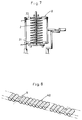
- FIG. 1 is a schematic side view of an inner spring producing apparatus and FIG. 2 is a front view of the same.
- Numeral 1 in the illustration shows the entirety of the inner spring producing apparatus.
- the inner spring producing apparatus 1 comprises a coil spring producing section 3 for forming coil springs 2 from a wire; a coil spring feeding section 6 for feeding the coil springs 2 fed from the coil spring producing section 3 to coil spring supporting bars 5 embedded in a conveyer 4; a conveying section 7 including the conveyer 4 for conveying the coil springs 2 fed from the coil spring feeding section 6 with their supported by the supporting bars 5; a hardening-and-cooling section 8 for successively hardening the coil springs 2 and cooling them by blowing in the process of conveyance; a sheet feeding section 10 for feeding a double folded sheet 9 in which the coil springs 2 are inserted; a compression-and-insertion section 11 for compressing the coil springs 2 as hardened and cooled and inserting them in between the double folded sheet 9; a bonding section 12 for bonding the double folded sheet 9 inserting therein the coil springs 2 together, to form generally rectangular sheet casings casing therein the coil springs 2; a coil spring arraying section 13 via which the coil springs 2 compressed vertical
- the wire 15 is fed through a wire guide 17 to a round tool 19 via a pair of wire feed rollers 18 and is formed into a circular-arc form thereat. Then, the wire 15 formed into the circular-arc form is pressed at one end thereof by a pitch tool 20, to be formed into coils having prescribed pitches.
- the pitch tool 20 also acts as a device for making changes in pitch of the coil springs.
- the pitches of the coils thus successively formed are set in the following manner.
- an operating shaft 25 is rotated by a pitch adjuster 24 which is shifted sliding in contact with a profile of a pitch adjusting eccentric cam 22 which is assembled to a shaft 23 rotatably pivoted by a frame 21 of a part of the coil spring producing section 3.
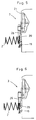
- the coil spring 2 When the pressing force of the pitch tool 20 to the wire 15 is strong, the coil spring 2 will have a large pitch and thus an increased repulsion, as shown in FIG. 4. When the pressing force is decreased, the coil spring 2 will have a small pitch or zero pitch (no gap between the coils) and thus a decreased repulsion, as shown in FIG. 5.
- the pitch of the coil springs can be variously changed by changing the position of the pitch adjuster 24 in the course of producing the coil springs.
- the round tool 19 is moved rightward or leftward in FIG. 3 in a swinging manner via an eccentric cam 28 which is assembled to a coil diameter adjusting shaft 27 pivoted by the frame 20 of a part of the coil spring producing section 3.
- the coil spring 2 formed When the round tool 19 is moved leftward, the coil spring 2 formed will have a reduced outer diameter; and when the round tool 19 is moved rightward, the coil spring 2 will have an increased outer diameter.
- the coil spring 2 of a barrel shape as shown in FIG. 6 or a hand-drum shape as opposed to the barrel shape, not shown, can be formed with ease.
- the coil springs 2 formed in the coil spring producing section 3 are cut with the cutter 26.
- the coil springs 2 thus cut with the cutter 26 are fed to the conveyer 4 of the conveying section 7 from a feeding guide 29 in front of it.
- the coil springs 2 fed to the conveyer 4 of the conveying section 7 are hardened and cooled by the hardening-and-insertion section 8 on their way to the compression-and-insertion section 11.
- the hardening-and-cooling section 8 comprises electrodes 30, 31 and a blower 32.
- the electrodes 30, 31 are brought into contact with the coil springs 2 at upper and lower portions thereof, to pass a current through the coil springs 2 from the electrodes 30, 31 so that the coil springs can be heated and thus hardened, as shown in FIG. 7.
- the coil springs 2 are cooled down to generally atmospheric temperature by the blower 32 for sending air to the coil springs 2, before the coil springs 2 are fed to the following compression-and-insertion section 11.
- the coil springs 2 fed from the hardening-and-cooling section 8 to the casing insertion section 5 are compressed by a spring press-in section 11 to be inserted in between doubled sheets.
- the casings are sealed at their portions between the coil springs 2 by a vertical sealing section 12.
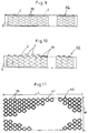
- the coil springs 2 of even in the number of turns (or coils) but different in pitch are then inserted in the cylindrical spring casings 39 of even length. If the spring casings 39 are opened at their insertion openings, the coil springs 2 having large pitches and thus strong repulsion will project greatly from the insertion openings, as shown in FIG. 10.
- the coil springs are partly varied in repulsion by making their pitches different, as mentioned above. Accordingly, when rows of inner springs 40 are so connected via adhesive or hook rings as to have a length extending in the widthwise direction, as shown in FIG. 11, to form a mattress 41 of a bed, the mattress 41 will have resilient forces partly varied with respect to the lengthwise direction L of the mattress 41.
- the mattress 41 of the bed like that shown in FIG. 12 has a variety of sizes, including the so-called, single size, semi-double size, double size, queen size and king size, it commonly has a substantially uniform lengthwise dimension of about 2 m. Accordingly, the way of rows of inner springs being arranged in parallel in the longitudinal direction, as in the example of the invention, enables the width W to be changed with efficiency by simply increasing or decreasing a row of cased inner springs to be connected, without the need for changing the length L of a row of cased inner springs, as in the conventional.
- the mattress 41 of the bed as shown in FIG. 12 may be formed by the inner springs 40 of the invention being arranged in parallel not only in the lengthwise direction but also in the widthwise direction as shown in FIG. 13.
- the embodiment of the invention includes the process of the coil springs being hardened and then cooled down, but the hardening/cooling process may, of course, be omitted.
- the respective sections of the inner spring producing apparatus are arranged in series from the coil spring producing section to the casing insertion section, but those sections may, of course, be separated so that the respective processes can be done in different places.
- the inner springs which in illustration are explained taking the application to the mattress of the bed as an example, may, of course, be applied to sofas or seats used in, for example, trains and motorcars, without limiting to the examples above.
- the invention is so constructed that the repulsion of the coil springs can be varied by varying the pitches of the coil springs to be cased in a predetermined number of spring casing portions.
- This construction enables a mattress of a bed, for example, to have partly varied repulsion with respect to widthwise direction of the mattress of the bed by simply arranging the coil springs of different repulsion in place in the inner springs.
- This enables the inner springs of partly different repulsion to be successively produced, thus providing the advantageous effect of providing improved productivity with significantly reduced manufacturing costs.
- the coil springs having the resiliency suitable for the distribution of weight exerted on the mattress of the bed can be produced with ease, the fatigue of the mattress can be prevented as permanently as possible. This can provide the advantageous effect of providing an improved durability of bedding, such as beds, and furniture and thus an improved quality of goods.
- the repulsion of the coil springs can be varied simply by changing the pitches of the coil springs by means of the pitch setting means, thus producing the effect that varied resiliency of the coil springs in the inner springs can be achieved even by the conventional type of inner spring producing apparatus having no energizing type hardening device.
- the difference in repulsion can be further increased by using the pitch setting means in combination with the energizing type hardening device.
- the coil springs set at different resilient forces by the pitch setting means are inserted in the spring casing portions in the order in which they are set at different resilient forces, the need for each of the coil springs separately produced by several coil spring producing apparatus being adequately controlled, as in the prior art, can be eliminated. Also, since the miss-casing of the coil springs in the spring casing portions of the cylindrical casings can be surely prevented, there can produce the advantageous effect of providing significantly improved reliability of the bedding, such as beds, and furniture.
Landscapes
- Engineering & Computer Science (AREA)
- Mechanical Engineering (AREA)
- Springs (AREA)
- Mattresses And Other Support Structures For Chairs And Beds (AREA)
- Wire Processing (AREA)
Applications Claiming Priority (2)
| Application Number | Priority Date | Filing Date | Title |
|---|---|---|---|
| JP10217814A JP2000041792A (ja) | 1998-07-31 | 1998-07-31 | 家具並びに寝具に装着されるインナースプリング及びその製造方法 |
| JP21781498 | 1998-07-31 |
Publications (2)
| Publication Number | Publication Date |
|---|---|
| EP0976678A2 true EP0976678A2 (fr) | 2000-02-02 |
| EP0976678A3 EP0976678A3 (fr) | 2000-06-28 |
Family
ID=16710164
Family Applications (1)
| Application Number | Title | Priority Date | Filing Date |
|---|---|---|---|
| EP98310806A Withdrawn EP0976678A3 (fr) | 1998-07-31 | 1998-12-31 | Ensemble de ressorts pour mobilier et matelas et son procédé de fabrication |
Country Status (5)
| Country | Link |
|---|---|
| US (1) | US6170807B1 (fr) |
| EP (1) | EP0976678A3 (fr) |
| JP (1) | JP2000041792A (fr) |
| CN (1) | CN1167605C (fr) |
| CA (1) | CA2258713C (fr) |
Families Citing this family (19)
| Publication number | Priority date | Publication date | Assignee | Title |
|---|---|---|---|---|
| US6898813B2 (en) * | 2001-10-24 | 2005-05-31 | Agro Federkernproduktions Gmbh | Innerspring assembly |
| SE524127C2 (sv) * | 2002-10-29 | 2004-06-29 | Stjernfjaedrar Ab | Pocketmadrass med varierande höjd hos de inneslutna fjädrarna, samt en metod och en anordning för tillverkande av en dylik madrass |
| US6862763B2 (en) | 2002-12-02 | 2005-03-08 | L&P Property Management Company | Pocketed bedding or seating product having pockets of differing heights |
| US6813791B2 (en) * | 2003-03-04 | 2004-11-09 | L&P Property Management Company | Posturized pocketed bedding or seating product having pockets of differing heights |
| US6931685B2 (en) * | 2003-09-12 | 2005-08-23 | Dreamwell, Ltd. | One-sided mattress |
| JP3825027B2 (ja) * | 2003-11-07 | 2006-09-20 | ドリームベッド株式会社 | ポケットコイル袋列の製造方法及び該方法を用いるポケットコイル袋列の製造装置、並びにポケットコイルシート。 |
| GB0519009D0 (en) * | 2005-09-17 | 2005-10-26 | Harrison Bedding Ltd | Pocketted spring units |
| CN1962406B (zh) * | 2006-11-17 | 2010-05-12 | 李德锵 | 一种用于袋装弹簧机的压簧机构 |
| GB201102187D0 (en) * | 2011-02-09 | 2011-03-23 | Harrison Spinks Components Ltd | Multi-purpose resiient pad |
| EP3096653B1 (fr) * | 2014-01-22 | 2017-12-06 | Gabor Voros | Matelas fabriqué avec des ressorts en bois et son procédé de production |
| JP6314107B2 (ja) * | 2015-04-16 | 2018-04-18 | フランスベッド株式会社 | ばね体の焼き鈍し装置、ばね体の製造装置 |
| US10357116B2 (en) * | 2015-06-22 | 2019-07-23 | Zeplus, Llc | Pocketed foam systems and methods |
| JP2017202025A (ja) * | 2016-05-09 | 2017-11-16 | 西川産業株式会社 | ポケットコイルマットレスの製造方法 |
| US10477979B2 (en) | 2016-08-19 | 2019-11-19 | L&P Property Management Company | Pocketed spring assembly |
| US10577240B2 (en) * | 2017-04-17 | 2020-03-03 | Macao Commercial & Industrial Spring Mattress Manufacturer Macao TAIWA Machinery | Automatic bagged spring production apparatus |
| CA3060611C (fr) * | 2017-06-07 | 2021-12-28 | Spuhl Gmbh | Procede et appareil de fabrication d'une couche de recouvrement d'un materiau non tisse pour unite de ressorts internes et unite de ressorts internes |
| US10206515B1 (en) | 2017-09-20 | 2019-02-19 | L&P Property Management Company | Pocketed spring assembly |
| US11109686B2 (en) * | 2018-06-13 | 2021-09-07 | L&P Property Management Company | Method of making a continuous string of pocketed springs |
| CN116603955B (zh) * | 2023-06-20 | 2026-04-14 | 宁波市海曙妙盛机械厂(普通合伙) | 一种床网打边设备 |
Citations (1)
| Publication number | Priority date | Publication date | Assignee | Title |
|---|---|---|---|---|
| US5740597A (en) | 1995-12-25 | 1998-04-21 | Matsushita Industrial Co., Ltd. | Pocket coil spring producing apparatus |
Family Cites Families (5)
| Publication number | Priority date | Publication date | Assignee | Title |
|---|---|---|---|---|
| US3626523A (en) * | 1970-09-25 | 1971-12-14 | Harry J Robins | Bed foundation and mattress assembly |
| US5444905A (en) * | 1994-03-14 | 1995-08-29 | Simmons Company | Apparatus for manufacturing mattresses and box springs |
| US5987678A (en) * | 1995-05-10 | 1999-11-23 | Simmons Company | Multiple firmness mattress |
| US5868383A (en) * | 1997-03-27 | 1999-02-09 | L&P Property Management Company | Multiple rate coil spring assembly |
| JP2000015377A (ja) * | 1998-06-26 | 2000-01-18 | Matsushita Kogyo Kk | 収納型コイルバネ製造装置 |
-
1998
- 1998-07-31 JP JP10217814A patent/JP2000041792A/ja active Pending
- 1998-12-23 CN CNB981257895A patent/CN1167605C/zh not_active Expired - Lifetime
- 1998-12-31 US US09/223,713 patent/US6170807B1/en not_active Expired - Lifetime
- 1998-12-31 EP EP98310806A patent/EP0976678A3/fr not_active Withdrawn
-
1999
- 1999-01-14 CA CA002258713A patent/CA2258713C/fr not_active Expired - Lifetime
Patent Citations (1)
| Publication number | Priority date | Publication date | Assignee | Title |
|---|---|---|---|---|
| US5740597A (en) | 1995-12-25 | 1998-04-21 | Matsushita Industrial Co., Ltd. | Pocket coil spring producing apparatus |
Also Published As
| Publication number | Publication date |
|---|---|
| CA2258713A1 (fr) | 2000-01-31 |
| JP2000041792A (ja) | 2000-02-15 |
| CN1243802A (zh) | 2000-02-09 |
| CA2258713C (fr) | 2008-12-09 |
| EP0976678A3 (fr) | 2000-06-28 |
| US6170807B1 (en) | 2001-01-09 |
| CN1167605C (zh) | 2004-09-22 |
Similar Documents
| Publication | Publication Date | Title |
|---|---|---|
| US6170807B1 (en) | Inner springs for use in furniture and bedding and a producing method therefor | |
| US6119322A (en) | Cased coil spring producing apparatus | |
| US10961112B2 (en) | Method and apparatus for the production of a pocketed spring unit | |
| US7426810B2 (en) | Method and apparatus for producing pocket coil bag row | |
| CN109152488B (zh) | 用于制造弹性单元的装置和方法 | |
| EP1068147B1 (fr) | Appareil de production de ressorts helicoidaux dans des poches | |
| US6318416B1 (en) | Spring interior and method of making same | |
| US6758078B2 (en) | Spring coil assembly and system for making the same | |
| US5139054A (en) | Spring interior forming and assembling apparatus | |
| EP0941962A1 (fr) | Noyau à ressorts pour mobilier ou matelas, et méthode pour sa fabrication | |
| US3454054A (en) | Spring seats and the like articles | |
| EP1052920B1 (fr) | Partie interieure de matelas a ressorts et procede de fabrication associe | |
| US5934339A (en) | Varied coil spring interior forming method and apparatus | |
| US4472849A (en) | Bedspring assembly with novel border wire and method of forming the latter | |
| CA1327120C (fr) | Appareil servant a la fabrication de ressorts | |
| HK1033930B (en) | Apparatus for the production of pocketed coil springs |
Legal Events
| Date | Code | Title | Description |
|---|---|---|---|
| PUAI | Public reference made under article 153(3) epc to a published international application that has entered the european phase |
Free format text: ORIGINAL CODE: 0009012 |
|
| AK | Designated contracting states |
Kind code of ref document: A2 Designated state(s): AT BE CH CY DE DK ES FI FR GB GR IE IT LI LU MC NL PT SE |
|
| AX | Request for extension of the european patent |
Free format text: AL;LT;LV;MK;RO;SI |
|
| PUAL | Search report despatched |
Free format text: ORIGINAL CODE: 0009013 |
|
| AK | Designated contracting states |
Kind code of ref document: A3 Designated state(s): AT BE CH CY DE DK ES FI FR GB GR IE IT LI LU MC NL PT SE |
|
| AX | Request for extension of the european patent |
Free format text: AL;LT;LV;MK;RO;SI |
|
| RIC1 | Information provided on ipc code assigned before grant |
Free format text: 7B 68G 9/00 A, 7B 21F 3/02 B |
|
| AKX | Designation fees paid | ||
| REG | Reference to a national code |
Ref country code: DE Ref legal event code: 8566 |
|
| STAA | Information on the status of an ep patent application or granted ep patent |
Free format text: STATUS: THE APPLICATION IS DEEMED TO BE WITHDRAWN |
|
| 18D | Application deemed to be withdrawn |
Effective date: 20001228 |