EP0976873B2 - Ancrage d'injection ou précontrainte - Google Patents
Ancrage d'injection ou précontrainte Download PDFInfo
- Publication number
- EP0976873B2 EP0976873B2 EP98115218A EP98115218A EP0976873B2 EP 0976873 B2 EP0976873 B2 EP 0976873B2 EP 98115218 A EP98115218 A EP 98115218A EP 98115218 A EP98115218 A EP 98115218A EP 0976873 B2 EP0976873 B2 EP 0976873B2
- Authority
- EP
- European Patent Office
- Prior art keywords
- reinforcing elements
- accordance
- grouted
- grouted body
- foregoing
- Prior art date
- Legal status (The legal status is an assumption and is not a legal conclusion. Google has not performed a legal analysis and makes no representation as to the accuracy of the status listed.)
- Expired - Lifetime
Links
- 230000003014 reinforcing effect Effects 0.000 claims description 44
- 239000004570 mortar (masonry) Substances 0.000 claims description 14
- 229910000831 Steel Inorganic materials 0.000 claims description 6
- 239000010959 steel Substances 0.000 claims description 6
- 238000000034 method Methods 0.000 claims description 5
- 238000009826 distribution Methods 0.000 claims description 4
- 238000004519 manufacturing process Methods 0.000 claims description 4
- 239000002184 metal Substances 0.000 claims description 4
- 239000011152 fibreglass Substances 0.000 claims 1
- 238000002347 injection Methods 0.000 description 18
- 239000007924 injection Substances 0.000 description 18
- 239000004744 fabric Substances 0.000 description 16
- 230000002787 reinforcement Effects 0.000 description 9
- 238000010276 construction Methods 0.000 description 7
- 230000006835 compression Effects 0.000 description 6
- 238000007906 compression Methods 0.000 description 6
- 239000000463 material Substances 0.000 description 6
- 230000006978 adaptation Effects 0.000 description 4
- 238000003825 pressing Methods 0.000 description 4
- 238000004873 anchoring Methods 0.000 description 3
- 240000006829 Ficus sundaica Species 0.000 description 2
- 239000000243 solution Substances 0.000 description 2
- 210000002268 wool Anatomy 0.000 description 2
- 235000014443 Pyrus communis Nutrition 0.000 description 1
- 238000009435 building construction Methods 0.000 description 1
- 238000002788 crimping Methods 0.000 description 1
- 230000003628 erosive effect Effects 0.000 description 1
- 230000002349 favourable effect Effects 0.000 description 1
- 238000005429 filling process Methods 0.000 description 1
- 238000005242 forging Methods 0.000 description 1
- 239000011491 glass wool Substances 0.000 description 1
- 239000011440 grout Substances 0.000 description 1
- 229910052500 inorganic mineral Inorganic materials 0.000 description 1
- 238000009434 installation Methods 0.000 description 1
- 239000011707 mineral Substances 0.000 description 1
- 238000005065 mining Methods 0.000 description 1
- 230000002093 peripheral effect Effects 0.000 description 1
- 238000009418 renovation Methods 0.000 description 1
- 239000002689 soil Substances 0.000 description 1
- 239000007787 solid Substances 0.000 description 1
- 238000007711 solidification Methods 0.000 description 1
- 230000008023 solidification Effects 0.000 description 1
- 230000006641 stabilisation Effects 0.000 description 1
- 238000011105 stabilization Methods 0.000 description 1
- 229910001220 stainless steel Inorganic materials 0.000 description 1
- 239000010935 stainless steel Substances 0.000 description 1
- 230000007704 transition Effects 0.000 description 1
- 230000005641 tunneling Effects 0.000 description 1
Images

Classifications
-
- E—FIXED CONSTRUCTIONS
- E02—HYDRAULIC ENGINEERING; FOUNDATIONS; SOIL SHIFTING
- E02D—FOUNDATIONS; EXCAVATIONS; EMBANKMENTS; UNDERGROUND OR UNDERWATER STRUCTURES
- E02D5/00—Bulkheads, piles, or other structural elements specially adapted to foundation engineering
- E02D5/74—Means for anchoring structural elements or bulkheads
- E02D5/80—Ground anchors
-
- E—FIXED CONSTRUCTIONS
- E21—EARTH OR ROCK DRILLING; MINING
- E21D—SHAFTS; TUNNELS; GALLERIES; LARGE UNDERGROUND CHAMBERS
- E21D20/00—Setting anchoring-bolts
- E21D20/02—Setting anchoring-bolts with provisions for grouting
- E21D20/021—Grouting with inorganic components, e.g. cement
-
- E—FIXED CONSTRUCTIONS
- E21—EARTH OR ROCK DRILLING; MINING
- E21D—SHAFTS; TUNNELS; GALLERIES; LARGE UNDERGROUND CHAMBERS
- E21D21/00—Anchoring-bolts for roof, floor in galleries or longwall working, or shaft-lining protection
- E21D21/0026—Anchoring-bolts for roof, floor in galleries or longwall working, or shaft-lining protection characterised by constructional features of the bolts
- E21D21/006—Anchoring-bolts made of cables or wires
-
- E—FIXED CONSTRUCTIONS
- E21—EARTH OR ROCK DRILLING; MINING
- E21D—SHAFTS; TUNNELS; GALLERIES; LARGE UNDERGROUND CHAMBERS
- E21D21/00—Anchoring-bolts for roof, floor in galleries or longwall working, or shaft-lining protection
- E21D21/0026—Anchoring-bolts for roof, floor in galleries or longwall working, or shaft-lining protection characterised by constructional features of the bolts
- E21D21/0073—Anchoring-bolts having an inflatable sleeve, e.g. hollow sleeve expanded by a fluid
-
- E—FIXED CONSTRUCTIONS
- E02—HYDRAULIC ENGINEERING; FOUNDATIONS; SOIL SHIFTING
- E02D—FOUNDATIONS; EXCAVATIONS; EMBANKMENTS; UNDERGROUND OR UNDERWATER STRUCTURES
- E02D2250/00—Production methods
- E02D2250/003—Injection of material
-
- E—FIXED CONSTRUCTIONS
- E02—HYDRAULIC ENGINEERING; FOUNDATIONS; SOIL SHIFTING
- E02D—FOUNDATIONS; EXCAVATIONS; EMBANKMENTS; UNDERGROUND OR UNDERWATER STRUCTURES
- E02D2300/00—Materials
- E02D2300/0026—Metals
- E02D2300/0029—Steel; Iron
-
- E—FIXED CONSTRUCTIONS
- E02—HYDRAULIC ENGINEERING; FOUNDATIONS; SOIL SHIFTING
- E02D—FOUNDATIONS; EXCAVATIONS; EMBANKMENTS; UNDERGROUND OR UNDERWATER STRUCTURES
- E02D2300/00—Materials
- E02D2300/0026—Metals
- E02D2300/0029—Steel; Iron
- E02D2300/0034—Steel; Iron in wire form
-
- E—FIXED CONSTRUCTIONS
- E02—HYDRAULIC ENGINEERING; FOUNDATIONS; SOIL SHIFTING
- E02D—FOUNDATIONS; EXCAVATIONS; EMBANKMENTS; UNDERGROUND OR UNDERWATER STRUCTURES
- E02D37/00—Repair of damaged foundations or foundation structures
-
- E—FIXED CONSTRUCTIONS
- E02—HYDRAULIC ENGINEERING; FOUNDATIONS; SOIL SHIFTING
- E02D—FOUNDATIONS; EXCAVATIONS; EMBANKMENTS; UNDERGROUND OR UNDERWATER STRUCTURES
- E02D5/00—Bulkheads, piles, or other structural elements specially adapted to foundation engineering
- E02D5/22—Piles
- E02D5/54—Piles with prefabricated supports or anchoring parts; Anchoring piles
-
- F—MECHANICAL ENGINEERING; LIGHTING; HEATING; WEAPONS; BLASTING
- F16—ENGINEERING ELEMENTS AND UNITS; GENERAL MEASURES FOR PRODUCING AND MAINTAINING EFFECTIVE FUNCTIONING OF MACHINES OR INSTALLATIONS; THERMAL INSULATION IN GENERAL
- F16H—GEARING
- F16H57/00—General details of gearing
- F16H57/04—Features relating to lubrication or cooling or heating
- F16H57/0402—Cleaning of lubricants, e.g. filters or magnets
- F16H57/0404—Lubricant filters
Definitions
- the invention relates to a grout for Nachbewehrung of historical buildings and for the distribution of mechanical stresses to be used in holes, slots or the like openings, with a centrally disposed filling hose and at least one surrounding this filling hose tissue stocking.
- injection or injection anchors are used for the attachment of building parts on unsafe surfaces.
- injection or injection anchors are according to DIN 4125 to components in which by pressing in injection mortar around the back of a introduced into the ground Stahlzuggliedes a Anpreßanker is made, which is connected via Stahlzugglieder and anchor head with the component to be anchored or mountain part.
- injection anchor Another large area of application is the anchoring of damaged masonry or concrete parts in building construction, bridge construction or civil engineering. Injection or injection anchor are also used in tunneling for anchoring the tunnel inner shells, for grouting and for needling of the hanging wall in mining. Such injection anchors are listed, for example, in DIN 4125 and 4128.
- an injection anchor to be inserted into a predrilled hole will have a centrally located anchor bolt which is tightly enclosed by a tube of flexible material.
- This anchoring bolt which is designed as a solid bolt, can be processed consuming by forging.
- the injection anchor can thus be produced only factory. An adaptation to specific conditions, such as a changed load or torque transfer, is not possible at the construction site.
- the known injection or injection anchor are not or not particularly suitable for this purpose.
- the known injection or injection anchors are factory-made, so that the borehole depths from which special voltage or load transfers should take place, must be known in the armature production, but this raises significant production problems, since this is custom-made. A factory mass production can not be carried out then.
- the invention is based on the object of providing a compact which satisfies the requirements locally, ie. on the site, adapted and assembled in a simple manner, mounted and can be used immediately.
- the stitches of the fabric stocking are designed such that only a small part of the contents can escape radially, whereby this expands and the reinforcing elements are urged in an advantageous manner to the outer periphery.
- the reinforcing elements are advantageously arranged along the longitudinal axis of the pressed body outside of the inner filling hose, which are selectively connected to the tissue of the stocking, so that a positional fixation of the reinforcing elements is ensured after the filling of the pressed body.
- the filling hose and / or the fabric stocking is stretchable, so that an adaptation to the borehole is given, which must be designed according to the loads to be removed or stresses to be displaced. This results in the same basic elements a large margin for an adaptation of the pressed body.
- the filling hose and / or the fabric stocking is formed at least in sections as Metallgewirk, whereby the application possibilities are considerably expanded.
- the knitted fabric is formed, for example, from very thin wires or metal threads, which by their loop position have an expansion possibility of up to 20% of the stocking circumference.
- the inner centrally located filling hose is advantageously formed slightly shorter than the reinforcing elements, so that the filling material flows to the end of the filling hose, there exits undisturbed and within the outer tissue stocking, which is closed at its lower end, flows back until it is in the area Filling input from the borehole swells, indicating that the filling of the pressed body is completed successfully.
- the reinforcing elements are U-shaped, with their bent parts preferably being arranged at one end of the pressed body.
- the reinforcing elements of the compressed body are in its peripheral region. Further advantages of this variant are that the pull-out strength of such a bundle of reinforcing elements is substantially improved.
- the reinforcing elements are formed at least partially deformed over at least part of their length.
- each Reinforcing element has a group of wires and / or rods and / or - pipes at predetermined locations over a predetermined length for voltage shift or load and / or torque transfer from defined zones deformations. For example, if load or torque erosion in certain hinterbraterise areas of different sizes take place, so can be selected for each area wires, tubes or rods whose strength and number is determined according to the load or Momentabtragung, with a wire or rod bundles for the load transfer from a single area, while another bundle of wires, tubes or bars takes over the load or moment removal from another area.
- the reinforcing elements such as the wires and / or rods and / or tubes are corrugated, similar to a hairpin, and / or twisted, the deformations are preferably provided at the locations and in the areas in which the individual loads or Moments occur.
- steel or glass wool can be drilled.
- the compression body according to the invention also allows an improvement of the filling process by an end plate connected to the reinforcing elements or an adapter is provided on the head of the pressed body, which is connectable to a vibrating device, such that the generated mechanical vibrations are transferable to the reinforcing elements.
- vibration energy can be brought into all areas of the compressed body, so that the flowability of the filling material is improved.
- the compression body can be made in considerable lengths without problems in the introduction of the contents occur. It can thus be pressed body lengths of the order of 50 m and more produce. This also has the advantage that such compressed bodies on site, i. can be produced on the construction site.
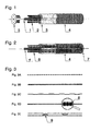
- the FIG. 1 shows an exploded perspective view of a compressed body according to the invention in the filled state.
- the inner filling hose 1 is surrounded by reinforcing elements 2, which may consist of rods, wires, tubes or tinker plates.
- the reinforcing elements 2 are in the present embodiment of rods or rods, which are each slightly shorter than the total length of the compressed body or can consist of sections not shown here.
- the length and the cross section of the reinforcement elements 2 are determined at the construction site on the basis of the determined data.
- a fabric stocking 4 which is closed at the foot of the crater, surrounds the entire body.
- the inner filling hose 1 is correspondingly shorter, so that the introduced through the filling hose 1 mortar leaves the filling hose at the foot of the crutch and is guided along the inner wall of the fabric stocking to the head of the crater until it exits there, so that the end of the compression of the Pressing body is displayed.
- the reinforcing elements they can be attached to the outer wall of the inner fabric stocking.
- the fastening means may be made of the same material as the fabric stocking, for example metal loops into which the reinforcing elements are inserted.
- the reinforcing elements 2 are connected to an end plate 5 in this illustrated embodiment.
- the position of the reinforcing elements is fixed once in the entrance area and on the other vibrational energies can be transmitted in order to facilitate the assembly process and to ensure the distribution and solidification of the mortar.
- the inner tissue and the outer tissue tube may also be made of different materials.
- the outer fabric stocking may be made more elastic than the filling tube. This ensures, for example, that the filling hose fully fulfills its transport function, while the fabric stocking adapts well to the unevenness of its surroundings and thus, for example, completely fills its borehole, so that a transition of the stresses or loads from the building to the compressed body is ensured.
- FIG. 2 shows a modified embodiment according to FIG. 1 ,
- the reinforcing elements 6 are formed in the form of wires, rods or rods and bent at one end 7 U-shaped. They extend over the entire length of the pressed body.
- FIG. 3 shows various embodiments of the reinforcing elements. That's how it shows FIG. 3a a deformed pole.
- the deformations may be provided in sections or over their entire length.
- the FIG. 3b shows a Zerrblech in the form of a narrow strip.
- the FIG. 3b represents a corrugated tube or corrugated pole.
- the 3d figure shows twisted wires in the steel wool 8 can be drilled.
- FIG. 3e gives a smooth steel with a reinforcement loop 9 for better adhesion again.
- FIGS. 3a to 3e shown reinforcing elements can be used in all combinations depending on the task.
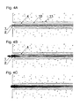
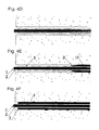
- FIGS. 4 A to D show the injection process in individual phases.
- FIG. 4A To FIG. 4A is located in the building 11, a bore 10 which is to be filled by a compression body according to the invention, for example, to relocate forces from stress fields. Because of this task, the most favorable injection body is determined for this purpose, the reinforcement elements are determined in the type, the size and their number on site and introduced into the wellbore 10. Then the filling is done with mortar, as in FIG. 4B is apparent. Here, the inner inflation hose 1 is inflated to its normal size. Thus, the reinforcing elements 2 take their final position and a predetermined position. It is thus ensured that a predetermined distribution of the reinforcing elements is maintained.
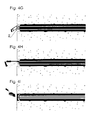
- FIGS. 4E to H show the final assembly of an injection body 13, which is already in the state filled with mortar in a borehole 10 and whose reinforcing elements 2 each have at their end a predetermined breaking point 14. Thereby, the protruding from the borehole 10 reinforcing elements 2 can be tested with a simple tool 15 and canceled and with another tool 16 (s. FIG. 4G ) are bent into each other, so that a filling and a closure of the borehole gets a sufficient grip and a connection with the pressed body (s. FIG. 4H ).
- a building has 17 vertically extending settlement cracks 18, whose stresses are to be absorbed and distributed with the aid of the compression bodies 13.
- the crimping body 13 is constructed as a ring anchor 19 with different reinforcing elements.
- the ring anchor 19 is formed reinforced in the region of the cracks 18, while the remaining regions of the armature have a lower reinforcement.
- the cracks 18 of the building 17 are created by a different background. While the right side of the house rests on a secure ground, subsidence has occurred in the left part, which requires stabilization.
- the injection body is also used according to the invention.
- the flowing back to the filling of the pressed body mortar is prevented by a ring plate 5 on the head part at its outlet and with a second higher pressure level of for example 10 bar further mortar is injected, so that the outer tissue trunk continues to expand and thus compresses the ground and the Pile foundation improved.
- the outer fabric stocking has different expansion radii along its longitudinal axis in accordance with the soil strength.
- the outer shell in its lower part have a pear shape, so that this shape is particularly suitable for piles and pile foundations.
- FIG. 5B shows an enlarged view of a masonry from a vertical crack 18 is traversed.
- FIG. 5C shows a cut to it.
- the injection anchor 13 is reinforced, while the remaining area of the ring anchor is equipped with a base reinforcement 22.
- a compression body which has a large range of applications in civil engineering, which can not be fully listed.
- the great advantage of the invention is that the crater on the spot, i. directly at the construction site the required conditions can be maximally adapted, whereby a very large variability is given.
Landscapes
- Engineering & Computer Science (AREA)
- Mining & Mineral Resources (AREA)
- Structural Engineering (AREA)
- Life Sciences & Earth Sciences (AREA)
- General Life Sciences & Earth Sciences (AREA)
- Geology (AREA)
- Geochemistry & Mineralogy (AREA)
- Civil Engineering (AREA)
- General Engineering & Computer Science (AREA)
- Paleontology (AREA)
- Chemical & Material Sciences (AREA)
- Inorganic Chemistry (AREA)
- Piles And Underground Anchors (AREA)
- Reinforcement Elements For Buildings (AREA)
Claims (11)
- Corps de pression (13) pour l'armature de renforcement de bâtiments historiques et pour assurer la répartition de tensions mécaniques, utilisé dans des trous de forage ou des fentes ou des ouvertures similaires, comportant un tuyau de remplissage (1) disposé au centre, se composant de tissu et ouvert au niveau des deux extrémités, au moins un manchon en tissu (4) entourant le tuyau de remplissage (1) et un remplissage de mortier (3) ainsi qu'un ou plusieurs éléments d'armature (2) exécutés sous forme de fil métallique et/ou de barre et/ou de tube et/ou de bande de tôle de traction et/ou d'acier fileté, conçus de façon à s'adapter sur place à toutes les conditions et disposés entre le tuyau de remplissage (1) et le manchon de tissu (4) et parallèlement à l'axe du corps de pression (13) et fixés en étant connectés au tuyau de remplissage (1) ou au manchon de tissu (4.
- Corps de pression selon la revendication 1, caractérisé en ce que le tuyau de remplissage (1) et le manchon de tissu (4) ont au moins par sections la configuration d'une structure métallique extensible.
- Corps de pression selon les revendications 1 ou 2, caractérisé en ce que le tuyau de remplissage (1) a une longueur légèrement inférieure à celle des éléments d'armature (2.
- Corps de pression selon l'une quelconque des revendications précédentes, caractérisé en ce que les éléments d'armature (2) ont une forme en U, leurs éléments recourbés étant disposés à la base du corps de pressage (13.
- Corps de pression selon l'une quelconque des revendications précédentes, caractérisé en ce que les éléments d'armature (2) ont une configuration déformée sur au moins une partie de leur longueur et présentent entre eux des longueurs différentes.
- Corps de pression selon l'une quelconque des revendications précédentes, caractérisé en ce que chaque élément d'armature (2) ou un groupe d'éléments d'armature (2) est ondulé et/ou torsadé à des endroits prédéfinis sur une longueur déterminée en vue de la transmission ou de l'amortissement de la tension à partir de zones définies de régions définies et sont reliés par de la laine de verre ou d'acier à amortissement de charge.
- Corps de pression selon l'une quelconque des revendications précédentes, caractérisé en ce que les éléments d'armature (2) sont serrés ou fixés mécaniquement par l'intermédiaire d'un dispositif de serrage, assurant ainsi leur fixation par tension, les éléments d'armature (2) situés en dehors du trou de forage (10) présentant des points de rupture théoriques (14) en vue de la détermination de la charge minimale pouvant être appliquée.
- Corps de pression selon l'une quelconque des revendications précédentes, caractérisé en ce que les éléments d'armature (2) sont reliés au niveau de la tête du corps de pression à une plaque d'extrémité (5) ou un adaptateur pouvant être relié(e) à un dispositif vibrant destiné à transmettre les vibrations mécaniques sur les éléments d'armature (2.
- Corps de pression selon l'une quelconque des revendications précédentes, caractérisé en ce que le rayon du manchon de tissu (4) est différent le long de son axe longitudinal.
- Procédé de production d'un corps de pression exécuté conformément aux revendications 1 à 9, caractérisé en ce qu'en fonction des valeurs déterminées des forces de traction, des tensions à transmettre ou des charges à amortir et de la position locale et de l'extension des champs de tension, un nombre calculé d'éléments d'armature (2) d'épaisseur déterminée est découpé à la longueur voulue et monté sur place en fonction de la profondeur des trous de forage et de la taille des fentes, est introduit dans le trou de forage/la fente et est pressé à l'intérieur.
- Procédé selon la revendication 10, caractérisé en ce qu'en fonction de la position et de la taille des champs de charge à amortir ou à transmettre dans le bâtiment, le nombre calculé d'éléments d'armature (2) est pourvu de déformations, un manchon de tissu (4) est tiré sur la disposition d'éléments d'armature (2), celui-ci étant relié par tension à la bordure extérieure d'une plaque d'extrémité (5) ou d'un tube d'extrémité, la bordure d'un alésage situé au centre étant reliée au tuyau de remplissage (1.
Applications Claiming Priority (3)
| Application Number | Priority Date | Filing Date | Title |
|---|---|---|---|
| DE19735457A DE19735457C2 (de) | 1997-08-16 | 1997-08-16 | Injektions- oder Verpreßkörper |
| DE19735457 | 1997-08-16 | ||
| US09/134,749 US6189281B1 (en) | 1997-08-16 | 1998-08-14 | Injection anchor |
Publications (3)
| Publication Number | Publication Date |
|---|---|
| EP0976873A1 EP0976873A1 (fr) | 2000-02-02 |
| EP0976873B1 EP0976873B1 (fr) | 2005-02-09 |
| EP0976873B2 true EP0976873B2 (fr) | 2009-12-16 |
Family
ID=26039170
Family Applications (1)
| Application Number | Title | Priority Date | Filing Date |
|---|---|---|---|
| EP98115218A Expired - Lifetime EP0976873B2 (fr) | 1997-08-16 | 1998-08-13 | Ancrage d'injection ou précontrainte |
Country Status (6)
| Country | Link |
|---|---|
| US (1) | US6189281B1 (fr) |
| EP (1) | EP0976873B2 (fr) |
| AU (1) | AU724785B2 (fr) |
| CA (1) | CA2245121C (fr) |
| DE (2) | DE19735457C2 (fr) |
| ES (1) | ES2236850T5 (fr) |
Families Citing this family (19)
| Publication number | Priority date | Publication date | Assignee | Title |
|---|---|---|---|---|
| ATE451514T1 (de) * | 2000-04-28 | 2009-12-15 | Peter James | Verfahren zur verstärkung einer struktur |
| DE102005005227A1 (de) * | 2005-02-03 | 2006-08-10 | International Intec Patent Holding Ets. | Injektionsanker oder Verpreßkörper zur Übertragung von mechanischen Spannungen in Bauwerken im Hoch- und Tiefbau |
| GB0611548D0 (en) * | 2006-06-12 | 2006-07-19 | Cintec Int Ltd | Method of reinforcing a structure and apparatus therefor |
| GB2462090B (en) * | 2008-07-22 | 2012-05-16 | Hutchinson Engineering Ltd | Support structures |
| CN101748759B (zh) * | 2009-12-16 | 2011-02-09 | 江苏建华管桩有限公司 | 管桩桩头的加固修补方法 |
| CA2838882C (fr) | 2011-06-14 | 2020-05-05 | John M. Wathne | Systeme de liaison, nettoyage et nouvelle cimentation de maconnerie a l'aide d'ancres de babord |
| SE535912C2 (sv) * | 2011-06-30 | 2013-02-12 | Leif Eriksson | Expanderbar bergbult och ett förfarande för tillverkning av en bergbult |
| JP2014051798A (ja) * | 2012-09-06 | 2014-03-20 | Splice Sleeve Japan Ltd | 鉄筋の継手工法 |
| CN103527229B (zh) * | 2013-10-23 | 2015-07-29 | 湖南科技大学 | 一种用于锚索的锚固剂保护破碎装置及锚固方法 |
| CN104532838B (zh) * | 2015-01-06 | 2016-03-16 | 济南轨道交通集团有限公司 | 预制预应力混凝土空心土钉及施工方法 |
| CN105274986A (zh) * | 2015-10-13 | 2016-01-27 | 中国十七冶集团有限公司 | 一种phc管桩的沉桩桩头破损修复方法 |
| CN105544392B (zh) * | 2015-12-22 | 2017-01-04 | 中国科学院武汉岩土力学研究所 | 锚孔内根键式承压机构和组装方法、根键式锚索、向锚孔注浆的方法 |
| CN108468336B (zh) * | 2018-04-16 | 2023-09-01 | 浙江大学 | 用于遗址保护的注浆机及施工方法 |
| CN109098742B (zh) * | 2018-08-20 | 2019-11-08 | 中国矿业大学 | 一种单锚集注式全长锚固的钢丝束及其支护方法 |
| DE202021000550U1 (de) | 2021-02-13 | 2022-05-16 | Gerolda Fulde | Textiles Tragglied zur Einleitung von Zug- oder Druckkräften in den Untergrund, welches für Böschungssicherungen, zur Verankerung von Schutzbauwerken gegen Naturgefahren und bei allgemeinen geotechnischen Anwendungen eingesetzt wird und mit dem Untergrund einen direkten Kraftübertrag herstellt |
| CN113774970B (zh) * | 2021-08-05 | 2023-01-10 | 深圳宏业基岩土科技股份有限公司 | 灌注桩嵌岩段缺陷修复施工方法 |
| CN114108718B (zh) * | 2021-12-10 | 2024-09-24 | 江西联保工程咨询有限公司 | 用于现场位移检测及注浆的泄浆阀装置及缸外注浆方法 |
| CN114718602B (zh) * | 2022-03-31 | 2024-08-13 | 广西北投交通养护科技集团有限公司 | 隧道穿越松散碎石弃土堆的加固处治方法 |
| EP4717822A1 (fr) * | 2024-09-25 | 2026-04-01 | Vidatek B.V. | Procédé et système de fondation d'une construction ou d'une partie de construction sacée |
Citations (3)
| Publication number | Priority date | Publication date | Assignee | Title |
|---|---|---|---|---|
| EP0330114A1 (fr) † | 1988-02-23 | 1989-08-30 | International Intec Patent Holding Establishment | Ancre d'injection à enfoncer dans le trou prépercé de la paroi à plusieurs couches d'un bâtiment |
| DE4112128A1 (de) † | 1991-04-13 | 1992-10-15 | Int Intec Patent Holding Ets | Verfahren und injektionsanker zum sanieren von doppelschaligen gebaeudewaenden |
| US5216857A (en) † | 1990-08-08 | 1993-06-08 | International Intec Patent Holding Establishment | Apparatus and method for enabling a subsequent stabilization of buildings |
Family Cites Families (10)
| Publication number | Priority date | Publication date | Assignee | Title |
|---|---|---|---|---|
| AT344117B (de) * | 1976-01-29 | 1978-07-10 | Gd Anker Gmbh & Co Kg | Verfahren zum setzen eines gebirgsankers sowie schlauch und verankerungselement zur durchfuehrung des verfahrens |
| FR2423591A1 (fr) * | 1978-04-18 | 1979-11-16 | Sif Entreprise Bachy | Ameliorations a la realisation de tirants ancres |
| CH635885A5 (en) * | 1979-02-20 | 1983-04-29 | Stump Bohr Ag | Anchorage for structural members in soil or in rock and method of producing this anchorage |
| US4343399A (en) * | 1981-04-13 | 1982-08-10 | Celtite, Inc. | Two component device for use in anchor bolting and method of anchoring |
| US4424861A (en) * | 1981-10-08 | 1984-01-10 | Halliburton Company | Inflatable anchor element and packer employing same |
| DE3146649A1 (de) * | 1981-11-25 | 1983-06-01 | International Intec Co. Establishment, Vaduz | "in vorgebohrte loecher einzusetzender injektionsanker" |
| CH671790A5 (fr) * | 1986-08-13 | 1989-09-29 | Vsl Int Ag | |
| DE3712463A1 (de) * | 1987-04-13 | 1988-10-27 | Hilti Ag | Befestigung auf hohlraeume aufweisendem untergrund |
| DE3737894A1 (de) * | 1987-11-07 | 1989-05-18 | Ferdinand Dr Lutz | Propeller mit verstellbaren blaettern |
| DE4018703C1 (en) * | 1990-06-12 | 1991-08-01 | Johannes Radtke | Improved cable anchor - includes several laminations and has fixing at end towards bottom of bore hole |
-
1997
- 1997-08-16 DE DE19735457A patent/DE19735457C2/de not_active Expired - Fee Related
-
1998
- 1998-08-13 ES ES98115218T patent/ES2236850T5/es not_active Expired - Lifetime
- 1998-08-13 EP EP98115218A patent/EP0976873B2/fr not_active Expired - Lifetime
- 1998-08-13 DE DE59812561T patent/DE59812561D1/de not_active Expired - Lifetime
- 1998-08-14 US US09/134,749 patent/US6189281B1/en not_active Expired - Lifetime
- 1998-08-14 CA CA002245121A patent/CA2245121C/fr not_active Expired - Fee Related
- 1998-08-14 AU AU79972/98A patent/AU724785B2/en not_active Ceased
Patent Citations (3)
| Publication number | Priority date | Publication date | Assignee | Title |
|---|---|---|---|---|
| EP0330114A1 (fr) † | 1988-02-23 | 1989-08-30 | International Intec Patent Holding Establishment | Ancre d'injection à enfoncer dans le trou prépercé de la paroi à plusieurs couches d'un bâtiment |
| US5216857A (en) † | 1990-08-08 | 1993-06-08 | International Intec Patent Holding Establishment | Apparatus and method for enabling a subsequent stabilization of buildings |
| DE4112128A1 (de) † | 1991-04-13 | 1992-10-15 | Int Intec Patent Holding Ets | Verfahren und injektionsanker zum sanieren von doppelschaligen gebaeudewaenden |
Also Published As
| Publication number | Publication date |
|---|---|
| ES2236850T3 (es) | 2005-07-16 |
| CA2245121A1 (fr) | 1999-02-16 |
| DE59812561D1 (de) | 2005-03-17 |
| EP0976873A1 (fr) | 2000-02-02 |
| AU724785B2 (en) | 2000-09-28 |
| DE19735457C2 (de) | 2002-07-18 |
| ES2236850T5 (es) | 2010-04-09 |
| AU7997298A (en) | 1999-02-25 |
| CA2245121C (fr) | 2006-08-01 |
| EP0976873B1 (fr) | 2005-02-09 |
| DE19735457A1 (de) | 1999-02-18 |
| US6189281B1 (en) | 2001-02-20 |
Similar Documents
| Publication | Publication Date | Title |
|---|---|---|
| EP0976873B2 (fr) | Ancrage d'injection ou précontrainte | |
| EP0394179B1 (fr) | Boulon d'ancrage rigide profilé et extensible avec élément d'expansion | |
| DE69837524T2 (de) | Verfahren zur Herstellung einer Verankerung, Verankerungsteil und Spannelement zu diesem Zweck | |
| EP0014426A1 (fr) | Ancre de roche | |
| DE2041526B2 (de) | Zugglied fuer einen verpressanker | |
| EP0317547A1 (fr) | Boulon d'ancrage de roche | |
| CH635885A5 (en) | Anchorage for structural members in soil or in rock and method of producing this anchorage | |
| CH698304B1 (de) | Drahtseilanker, insbesondere für Steinschlag- oder Lawinenschutzverbauungen. | |
| DE102009001749B4 (de) | Anschlussvorrichtung und Verfahren zur Erstellung eines Anschlusses | |
| DE3320460C1 (de) | Nachgiebiger Gebirgsanker | |
| DE19513202A1 (de) | Vorrichtung zur Verankerung von Bewehrungs- bzw. Spannstählen in Verankerungsgründen | |
| DE3012613C2 (de) | Ankerausbau für Strecken des untertägigen Bergbaus, Tunnel o.dgl. | |
| DE202010004381U1 (de) | Druckrohr sowie daraus hergestellter Erdanker | |
| CH676015A5 (fr) | ||
| EP2829661A1 (fr) | Ancrage de terre ou de rocher | |
| DE2353652C2 (de) | Ausbaubarer Verpreßanker mit verlorenem Ankerkörper | |
| EP0056255A1 (fr) | Dispositif pour l'attachement d'objets à un mur en béton | |
| DE3838880C1 (en) | Method of producing a grouted anchor, and grouted anchor for carrying out the method | |
| EP3848512B1 (fr) | Procédé de création d'un élément de fondation dans le sol et élément de fondation | |
| EP0350454A2 (fr) | Procédé pour former un organe de traction ancrable dans le sol | |
| EP0899382B1 (fr) | Elément d'ancrage d'un tirant ancrage | |
| DD291365A5 (de) | Anordnung von vorgefertigten ankerteilen an erdankern fuer bindige und mittelbindige boeden | |
| DE1634273C3 (de) | Verpreßanker | |
| EP1688545A1 (fr) | Ancrage d'injection ou précontrainte pour la construction en surface et la construction souterraine | |
| EP2808449A1 (fr) | Pieu foré pour fondation |
Legal Events
| Date | Code | Title | Description |
|---|---|---|---|
| PUAI | Public reference made under article 153(3) epc to a published international application that has entered the european phase |
Free format text: ORIGINAL CODE: 0009012 |
|
| AK | Designated contracting states |
Kind code of ref document: A1 Designated state(s): BE CH DE ES FR GB IT LI NL |
|
| AX | Request for extension of the european patent |
Free format text: AL;LT;LV;MK;RO;SI |
|
| 17P | Request for examination filed |
Effective date: 20000308 |
|
| AKX | Designation fees paid |
Free format text: BE CH DE ES FR GB IT LI NL |
|
| 17Q | First examination report despatched |
Effective date: 20020207 |
|
| GRAH | Despatch of communication of intention to grant a patent |
Free format text: ORIGINAL CODE: EPIDOS IGRA |
|
| GRAS | Grant fee paid |
Free format text: ORIGINAL CODE: EPIDOSNIGR3 |
|
| GRAA | (expected) grant |
Free format text: ORIGINAL CODE: 0009210 |
|
| AK | Designated contracting states |
Kind code of ref document: B1 Designated state(s): BE CH DE ES FR GB IT LI NL |
|
| REG | Reference to a national code |
Ref country code: GB Ref legal event code: FG4D Free format text: NOT ENGLISH |
|
| REG | Reference to a national code |
Ref country code: CH Ref legal event code: EP |
|
| REF | Corresponds to: |
Ref document number: 59812561 Country of ref document: DE Date of ref document: 20050317 Kind code of ref document: P |
|
| GBT | Gb: translation of ep patent filed (gb section 77(6)(a)/1977) |
Effective date: 20050418 |
|
| REG | Reference to a national code |
Ref country code: ES Ref legal event code: FG2A Ref document number: 2236850 Country of ref document: ES Kind code of ref document: T3 |
|
| REG | Reference to a national code |
Ref country code: CH Ref legal event code: NV Representative=s name: DR. H. SCHWEIZER RECHTSANWALT |
|
| PLBI | Opposition filed |
Free format text: ORIGINAL CODE: 0009260 |
|
| PLAX | Notice of opposition and request to file observation + time limit sent |
Free format text: ORIGINAL CODE: EPIDOSNOBS2 |
|
| 26 | Opposition filed |
Opponent name: M.TECH PATRIMONIUM SA Effective date: 20051107 |
|
| ET | Fr: translation filed | ||
| NLR1 | Nl: opposition has been filed with the epo |
Opponent name: M.TECH PATRIMONIUM SA |
|
| PLAF | Information modified related to communication of a notice of opposition and request to file observations + time limit |
Free format text: ORIGINAL CODE: EPIDOSCOBS2 |
|
| PLBB | Reply of patent proprietor to notice(s) of opposition received |
Free format text: ORIGINAL CODE: EPIDOSNOBS3 |
|
| PUAH | Patent maintained in amended form |
Free format text: ORIGINAL CODE: 0009272 |
|
| STAA | Information on the status of an ep patent application or granted ep patent |
Free format text: STATUS: PATENT MAINTAINED AS AMENDED |
|
| PGFP | Annual fee paid to national office [announced via postgrant information from national office to epo] |
Ref country code: NL Payment date: 20090814 Year of fee payment: 12 |
|
| 27A | Patent maintained in amended form |
Effective date: 20091216 |
|
| AK | Designated contracting states |
Kind code of ref document: B2 Designated state(s): BE CH DE ES FR GB IT LI NL |
|
| REG | Reference to a national code |
Ref country code: CH Ref legal event code: AEN Free format text: AUFRECHTERHALTUNG DES PATENTES IN GEAENDERTER FORM |
|
| NLR2 | Nl: decision of opposition |
Effective date: 20091216 |
|
| REG | Reference to a national code |
Ref country code: ES Ref legal event code: DC2A Date of ref document: 20100204 Kind code of ref document: T5 |
|
| REG | Reference to a national code |
Ref country code: NL Ref legal event code: VDEP Effective date: 20091216 |
|
| PG25 | Lapsed in a contracting state [announced via postgrant information from national office to epo] |
Ref country code: NL Free format text: LAPSE BECAUSE OF FAILURE TO SUBMIT A TRANSLATION OF THE DESCRIPTION OR TO PAY THE FEE WITHIN THE PRESCRIBED TIME-LIMIT Effective date: 20091216 |
|
| PGFP | Annual fee paid to national office [announced via postgrant information from national office to epo] |
Ref country code: ES Payment date: 20100812 Year of fee payment: 13 Ref country code: CH Payment date: 20100706 Year of fee payment: 13 |
|
| REG | Reference to a national code |
Ref country code: CH Ref legal event code: PL |
|
| PG25 | Lapsed in a contracting state [announced via postgrant information from national office to epo] |
Ref country code: LI Free format text: LAPSE BECAUSE OF NON-PAYMENT OF DUE FEES Effective date: 20110831 Ref country code: CH Free format text: LAPSE BECAUSE OF NON-PAYMENT OF DUE FEES Effective date: 20110831 |
|
| REG | Reference to a national code |
Ref country code: ES Ref legal event code: FD2A Effective date: 20130404 |
|
| PG25 | Lapsed in a contracting state [announced via postgrant information from national office to epo] |
Ref country code: ES Free format text: LAPSE BECAUSE OF NON-PAYMENT OF DUE FEES Effective date: 20110814 |
|
| PGFP | Annual fee paid to national office [announced via postgrant information from national office to epo] |
Ref country code: FR Payment date: 20140821 Year of fee payment: 17 |
|
| PGFP | Annual fee paid to national office [announced via postgrant information from national office to epo] |
Ref country code: BE Payment date: 20140820 Year of fee payment: 17 |
|
| REG | Reference to a national code |
Ref country code: FR Ref legal event code: ST Effective date: 20160429 |
|
| PG25 | Lapsed in a contracting state [announced via postgrant information from national office to epo] |
Ref country code: FR Free format text: LAPSE BECAUSE OF NON-PAYMENT OF DUE FEES Effective date: 20150831 |
|
| PGFP | Annual fee paid to national office [announced via postgrant information from national office to epo] |
Ref country code: DE Payment date: 20160829 Year of fee payment: 19 Ref country code: GB Payment date: 20160819 Year of fee payment: 19 Ref country code: IT Payment date: 20160825 Year of fee payment: 19 |
|
| REG | Reference to a national code |
Ref country code: DE Ref legal event code: R082 Ref document number: 59812561 Country of ref document: DE Representative=s name: HUMBOLDT-PATENT HUEBNER NEUMANN RADWER WENZEL, DE |
|
| PG25 | Lapsed in a contracting state [announced via postgrant information from national office to epo] |
Ref country code: BE Free format text: LAPSE BECAUSE OF NON-PAYMENT OF DUE FEES Effective date: 20150831 |
|
| REG | Reference to a national code |
Ref country code: DE Ref legal event code: R119 Ref document number: 59812561 Country of ref document: DE |
|
| GBPC | Gb: european patent ceased through non-payment of renewal fee |
Effective date: 20170813 |
|
| PG25 | Lapsed in a contracting state [announced via postgrant information from national office to epo] |
Ref country code: DE Free format text: LAPSE BECAUSE OF NON-PAYMENT OF DUE FEES Effective date: 20180301 Ref country code: GB Free format text: LAPSE BECAUSE OF NON-PAYMENT OF DUE FEES Effective date: 20170813 |
|
| PG25 | Lapsed in a contracting state [announced via postgrant information from national office to epo] |
Ref country code: IT Free format text: LAPSE BECAUSE OF NON-PAYMENT OF DUE FEES Effective date: 20170813 |