EP0976893A2 - Zugangspanel für Pfosten - Google Patents
Zugangspanel für Pfosten Download PDFInfo
- Publication number
- EP0976893A2 EP0976893A2 EP99111080A EP99111080A EP0976893A2 EP 0976893 A2 EP0976893 A2 EP 0976893A2 EP 99111080 A EP99111080 A EP 99111080A EP 99111080 A EP99111080 A EP 99111080A EP 0976893 A2 EP0976893 A2 EP 0976893A2
- Authority
- EP
- European Patent Office
- Prior art keywords
- access panel
- pole
- shell
- panel according
- coupling
- Prior art date
- Legal status (The legal status is an assumption and is not a legal conclusion. Google has not performed a legal analysis and makes no representation as to the accuracy of the status listed.)
- Granted
Links
Images



Classifications
-
- E—FIXED CONSTRUCTIONS
- E04—BUILDING
- E04H—BUILDINGS OR LIKE STRUCTURES FOR PARTICULAR PURPOSES; SWIMMING OR SPLASH BATHS OR POOLS; MASTS; FENCING; TENTS OR CANOPIES, IN GENERAL
- E04H12/00—Towers; Masts or poles; Chimney stacks; Water-towers; Methods of erecting such structures
- E04H12/003—Access covers or locks therefor
Definitions
- the present invention relates to an access panel for a pole.
- an opening is formed at a certain easily reachable height of the pole, which allows access to the inside where a terminal strip with associated accessories for connecting the electric components is accommodated;
- said opening usually has a vertically elongated rectangular shape with semicircular short sides, and said opening is closed with an access panel which is fixed by acting on two or more screws for coupling to the pole: coupling is achieved by screwing the screws into internal anchors which, through of the screwing action, clamp the edge of the opening.
- the coupling of the access panel to the pole is of course hermetic to prevent water from entering the pole and reaching the terminal strip.
- pole fixing screws can be actuated with conventional screwdrivers or with screwdrivers with a cross-shaped or star-shaped head or with hexagonal profiles which are easily available and can be replaced with makeshift tools which allow vandals, children or the like to open the access panel.
- the technical aim of the present invention is to obviate the above-cited drawbacks of conventional devices, i.e., to provide an access panel for poles which has a profile with no external elements or edges, has simplified anchors which do not require add-on springs and nuts, has optimum watertightness and in which the fixing screws cannot be operated without a specific tool supplied with the access panel and not commercially available.
- an object of the present invention is to achieve the intended aim with a structure which is simple, relatively easy to provide in practice, safe in use, effective in operation and relatively low in cost.
- the present access panel for poles characterized in that it is constituted by a vertically elongated and shaped wraparound shell which is externally provided, proximate to its ends, with two recessed seats for the snap insertion of rustproof retention bushings for respective effraction-resistant fixing screws which are screwed substantially at the center of corresponding shaped brackets for coupling to the pole which, at the end directed toward the center of the shell, are fork-shaped for a nonrotational coupling with pins located inside the shell, said shell having, toward the pole and in a peripheral region, a perimetric channel for a gasket.
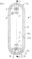
- the reference numeral 1 generally designates an access panel for poles P according to the invention.
- the access panel 1 is constituted by a vertically elongated shell 2 formed by pressing rustproof metal alloys: the shell 2 is shaped so as to have a substantially cylindrical profile which wraps around the pole, has a rectangular and vertically elongated shape in which the shorter side 3a and 3b are semicircular, is peripherally provided, toward the outside, with a smoothly rounded edge 4 and has absolutely no parts that protrude toward the outside of the profile.
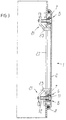
- the shell 2 is externally provided, proximate to its ends, with two recessed seats 5 and 6 which are crossed by respective through holes 7 for the snap insertion of rustproof retention bushings 8 made of a thermoplastic material;
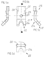
- the bushings 8 have a portion 9 which has a larger diameter, with a recess 10 for the head 11 of an effraction-resistant screw 12; said recess is provided, along its perimeter, with three spaced teeth 13 for retaining the head of the screw;
- the bushings 8 have a portion 14 which has a reduced diameter, is crossed by a hole 15 for the stem of the screw 12, is externally provided, at its end, with an annular raised portion 16 for snap coupling in the through holes 7 of the recessed seats 5 and 6, and is longitudinally provided with three notches 17 which allow its deformation for coupling to the shell 2.
- an axial symmetrical cavity 18 with three sides 19, each of which is cylindrical, has its concavity directed toward the axis of the screw and its radius of curvature arranged so as to coincide with the mutually opposite vertex: in this manner it is impossible to operate the screw with a screwdriver or with tools which are commercially available; if they are inserted, such tools merely turn idly by pivoting in succession on the various edges; any attempt at actuation with improper tools is further ineffective.
- the screws screw into substantially central threaded holes 20 of two corresponding shaped brackets 21, respectively an upper one and a lower one, which are perpendicular to the screw and are designed for coupling to the pole:
- the shaped brackets 21 are obtained by die-pressing high-strength materials, such as steel, and have a portion 21a which is directed toward the center of the shell, is folded toward the outside of the pole and is shaped like a fork 22 for nonrotational coupling to a corresponding pin 23 located inside the shell.
- the bracket On the other portion 21b, the bracket has two complementary lateral folds 24 for adapting to the internal profile of the pole P in order to eliminate the possibility of unauthorized extraction and/or removal.
- the shell 2 is internally provided with a pair of symmetrical pins 25 and 26 which are adapted to center the access panel in the slot 27 of the pole P and to prevent it from sliding downward during the operations for mounting on the pole.
- the shell is peripherally provided, toward the pole, with a perimetric channel 28 for a gasket 29 made of a material such as rubber, which has a substantially elliptical cross-section; the channel 28 is provided with sets of staggered teeth 30a, 30b, 31 distributed on its two facing sides in order to retain the gasket in the access panel.
- a threaded seat 32 for a screw for electrical connection to the ground is provided inside the access panel.
Landscapes
- Engineering & Computer Science (AREA)
- Architecture (AREA)
- Civil Engineering (AREA)
- Structural Engineering (AREA)
- Load-Bearing And Curtain Walls (AREA)
- Specific Sealing Or Ventilating Devices For Doors And Windows (AREA)
- Lock And Its Accessories (AREA)
- Power-Operated Mechanisms For Wings (AREA)
- Motor Or Generator Frames (AREA)
- Iron Core Of Rotating Electric Machines (AREA)
- Rod-Shaped Construction Members (AREA)
- Casings For Electric Apparatus (AREA)
- Gasket Seals (AREA)
Applications Claiming Priority (2)
| Application Number | Priority Date | Filing Date | Title |
|---|---|---|---|
| IT1998BO000466A IT1306270B1 (it) | 1998-07-29 | 1998-07-29 | Portello per palo |
| ITBO980466 | 1998-07-29 |
Publications (3)
| Publication Number | Publication Date |
|---|---|
| EP0976893A2 true EP0976893A2 (de) | 2000-02-02 |
| EP0976893A3 EP0976893A3 (de) | 2000-12-20 |
| EP0976893B1 EP0976893B1 (de) | 2004-03-24 |
Family
ID=11343338
Family Applications (1)
| Application Number | Title | Priority Date | Filing Date |
|---|---|---|---|
| EP99111080A Expired - Lifetime EP0976893B1 (de) | 1998-07-29 | 1999-06-17 | Zugangspanel für Pfosten |
Country Status (5)
| Country | Link |
|---|---|
| EP (1) | EP0976893B1 (de) |
| AT (1) | ATE262633T1 (de) |
| DE (1) | DE69915743D1 (de) |
| ES (1) | ES2214770T3 (de) |
| IT (1) | IT1306270B1 (de) |
Cited By (2)
| Publication number | Priority date | Publication date | Assignee | Title |
|---|---|---|---|---|
| EP1681408A2 (de) | 2005-01-17 | 2006-07-19 | Zaklad Produkcji Sprzetu Oswietleniowego "ROSA"-Stanislaw ROSA | Verschluss eines Hohlraums eines Lamppfosten |
| JP2017002680A (ja) * | 2015-06-16 | 2017-01-05 | 株式会社栃木屋 | 施錠装置 |
Family Cites Families (2)
| Publication number | Priority date | Publication date | Assignee | Title |
|---|---|---|---|---|
| GB2110265A (en) * | 1981-09-30 | 1983-06-15 | Hemcol Limited | Door for a lamp standard column |
| GB2255577B (en) * | 1991-05-10 | 1994-09-07 | British Steel Plc | Closures for support columns |
-
1998
- 1998-07-29 IT IT1998BO000466A patent/IT1306270B1/it active
-
1999
- 1999-06-17 AT AT99111080T patent/ATE262633T1/de not_active IP Right Cessation
- 1999-06-17 EP EP99111080A patent/EP0976893B1/de not_active Expired - Lifetime
- 1999-06-17 DE DE69915743T patent/DE69915743D1/de not_active Expired - Lifetime
- 1999-06-17 ES ES99111080T patent/ES2214770T3/es not_active Expired - Lifetime
Cited By (3)
| Publication number | Priority date | Publication date | Assignee | Title |
|---|---|---|---|---|
| EP1681408A2 (de) | 2005-01-17 | 2006-07-19 | Zaklad Produkcji Sprzetu Oswietleniowego "ROSA"-Stanislaw ROSA | Verschluss eines Hohlraums eines Lamppfosten |
| EP1681408A3 (de) * | 2005-01-17 | 2006-12-06 | Zaklad Produkcji Sprzetu Oswietleniowego "ROSA"-Stanislaw ROSA | Verschluss eines Hohlraums eines Lamppfosten |
| JP2017002680A (ja) * | 2015-06-16 | 2017-01-05 | 株式会社栃木屋 | 施錠装置 |
Also Published As
| Publication number | Publication date |
|---|---|
| ES2214770T3 (es) | 2004-09-16 |
| IT1306270B1 (it) | 2001-06-04 |
| DE69915743D1 (de) | 2004-04-29 |
| EP0976893B1 (de) | 2004-03-24 |
| EP0976893A3 (de) | 2000-12-20 |
| ATE262633T1 (de) | 2004-04-15 |
| ITBO980466A1 (it) | 2000-01-29 |
Similar Documents
| Publication | Publication Date | Title |
|---|---|---|
| EP0653806B1 (de) | Verbindungbefestigung eines elektrischen Kabels | |
| US6634842B2 (en) | Crime prevention screw, embedding material of screw head, screw-use crime prevention seat and crime prevention screw set | |
| CA2349645C (en) | Self-adjustable end cap assembly | |
| CA2497985A1 (en) | Electric box extender | |
| US6652236B2 (en) | Fan blade assembly and method of assembling | |
| CN1966309B (zh) | 挂钩附接单元 | |
| US4881354A (en) | Security grille and manufacturing method | |
| EP0976893B1 (de) | Zugangspanel für Pfosten | |
| ES2301191T3 (es) | Aparato electrico de empotrar con fijacion por garras. | |
| EP2484848B1 (de) | Aufnahme zum Halten der Einbauten einer Beleuchtungsvorrichtung innerhalb der Öffnung eines Lichtmastes | |
| EP0583611A1 (de) | Leicht montierbarer Metallzaun | |
| US6243977B1 (en) | Knockdown license plate frame | |
| US20100090186A1 (en) | Post Assembly | |
| EP1576636A1 (de) | Leuchtstofflampe mit diebstahlsicherung | |
| EP1736618A2 (de) | Ein einstellbarer Handgriff und ein Montageverfahren eines solchen Handgriffes | |
| KR101698005B1 (ko) | 보안등 고정구 | |
| DE9203739U1 (de) | Gehäuse für elektrische Kondensatoren | |
| JP4114872B2 (ja) | 塀上フェンス | |
| CN219180825U (zh) | 一种防水隐藏式多功能插座 | |
| JPH0636195Y2 (ja) | キャップ | |
| JP3077767U (ja) | 爪付きナットの構造 | |
| KR200392571Y1 (ko) | 코너용 멀티 콘센트기구 | |
| KR200306776Y1 (ko) | 자물쇠 고정구가 일체로 된 사물함용 손잡이 | |
| KR200295810Y1 (ko) | 차량용 도어풀핸들의 마운팅구조 | |
| CN203729741U (zh) | 后插式翻盖隐形弹簧翻转装置 |
Legal Events
| Date | Code | Title | Description |
|---|---|---|---|
| PUAI | Public reference made under article 153(3) epc to a published international application that has entered the european phase |
Free format text: ORIGINAL CODE: 0009012 |
|
| AK | Designated contracting states |
Kind code of ref document: A2 Designated state(s): AT DE ES FR GB GR PT |
|
| AX | Request for extension of the european patent |
Free format text: AL;LT;LV;MK;RO;SI |
|
| PUAL | Search report despatched |
Free format text: ORIGINAL CODE: 0009013 |
|
| AK | Designated contracting states |
Kind code of ref document: A3 Designated state(s): AT BE CH CY DE DK ES FI FR GB GR IE IT LI LU MC NL PT SE |
|
| AX | Request for extension of the european patent |
Free format text: AL;LT;LV;MK;RO;SI |
|
| RIC1 | Information provided on ipc code assigned before grant |
Free format text: 7E 04H 12/00 A, 7E 05B 65/00 B |
|
| 17P | Request for examination filed |
Effective date: 20010611 |
|
| AKX | Designation fees paid |
Free format text: AT DE ES FR GB GR PT |
|
| GRAP | Despatch of communication of intention to grant a patent |
Free format text: ORIGINAL CODE: EPIDOSNIGR1 |
|
| GRAS | Grant fee paid |
Free format text: ORIGINAL CODE: EPIDOSNIGR3 |
|
| GRAA | (expected) grant |
Free format text: ORIGINAL CODE: 0009210 |
|
| AK | Designated contracting states |
Kind code of ref document: B1 Designated state(s): AT DE ES FR GB GR PT |
|
| PG25 | Lapsed in a contracting state [announced via postgrant information from national office to epo] |
Ref country code: AT Free format text: LAPSE BECAUSE OF FAILURE TO SUBMIT A TRANSLATION OF THE DESCRIPTION OR TO PAY THE FEE WITHIN THE PRESCRIBED TIME-LIMIT Effective date: 20040324 |
|
| REG | Reference to a national code |
Ref country code: GB Ref legal event code: FG4D |
|
| REF | Corresponds to: |
Ref document number: 69915743 Country of ref document: DE Date of ref document: 20040429 Kind code of ref document: P |
|
| REG | Reference to a national code |
Ref country code: GR Ref legal event code: EP Ref document number: 20040401672 Country of ref document: GR |
|
| PG25 | Lapsed in a contracting state [announced via postgrant information from national office to epo] |
Ref country code: GB Free format text: LAPSE BECAUSE OF NON-PAYMENT OF DUE FEES Effective date: 20040624 |
|
| PG25 | Lapsed in a contracting state [announced via postgrant information from national office to epo] |
Ref country code: DE Free format text: LAPSE BECAUSE OF FAILURE TO SUBMIT A TRANSLATION OF THE DESCRIPTION OR TO PAY THE FEE WITHIN THE PRESCRIBED TIME-LIMIT Effective date: 20040625 |
|
| REG | Reference to a national code |
Ref country code: ES Ref legal event code: FG2A Ref document number: 2214770 Country of ref document: ES Kind code of ref document: T3 |
|
| ET | Fr: translation filed | ||
| PLBE | No opposition filed within time limit |
Free format text: ORIGINAL CODE: 0009261 |
|
| STAA | Information on the status of an ep patent application or granted ep patent |
Free format text: STATUS: NO OPPOSITION FILED WITHIN TIME LIMIT |
|
| GBPC | Gb: european patent ceased through non-payment of renewal fee |
Effective date: 20040624 |
|
| 26N | No opposition filed |
Effective date: 20041228 |
|
| PG25 | Lapsed in a contracting state [announced via postgrant information from national office to epo] |
Ref country code: PT Free format text: LAPSE BECAUSE OF NON-PAYMENT OF DUE FEES Effective date: 20040824 |
|
| REG | Reference to a national code |
Ref country code: FR Ref legal event code: PLFP Year of fee payment: 18 |
|
| PGFP | Annual fee paid to national office [announced via postgrant information from national office to epo] |
Ref country code: ES Payment date: 20160531 Year of fee payment: 18 Ref country code: GR Payment date: 20160524 Year of fee payment: 18 |
|
| PGFP | Annual fee paid to national office [announced via postgrant information from national office to epo] |
Ref country code: FR Payment date: 20160530 Year of fee payment: 18 |
|
| REG | Reference to a national code |
Ref country code: FR Ref legal event code: ST Effective date: 20180228 |
|
| PG25 | Lapsed in a contracting state [announced via postgrant information from national office to epo] |
Ref country code: GR Free format text: LAPSE BECAUSE OF NON-PAYMENT OF DUE FEES Effective date: 20180111 Ref country code: FR Free format text: LAPSE BECAUSE OF NON-PAYMENT OF DUE FEES Effective date: 20170630 |
|
| REG | Reference to a national code |
Ref country code: ES Ref legal event code: FD2A Effective date: 20181106 |
|
| PG25 | Lapsed in a contracting state [announced via postgrant information from national office to epo] |
Ref country code: ES Free format text: LAPSE BECAUSE OF NON-PAYMENT OF DUE FEES Effective date: 20170618 |