EP0976900A1 - Schloss, insbesondere Handschuhkastenschloss eines Kraftfahrzeuges - Google Patents
Schloss, insbesondere Handschuhkastenschloss eines Kraftfahrzeuges Download PDFInfo
- Publication number
- EP0976900A1 EP0976900A1 EP99112675A EP99112675A EP0976900A1 EP 0976900 A1 EP0976900 A1 EP 0976900A1 EP 99112675 A EP99112675 A EP 99112675A EP 99112675 A EP99112675 A EP 99112675A EP 0976900 A1 EP0976900 A1 EP 0976900A1
- Authority
- EP
- European Patent Office
- Prior art keywords
- coupling
- lock
- unlocking
- transmission element
- coupling element
- Prior art date
- Legal status (The legal status is an assumption and is not a legal conclusion. Google has not performed a legal analysis and makes no representation as to the accuracy of the status listed.)
- Granted
Links
- 230000008878 coupling Effects 0.000 claims abstract description 53
- 238000010168 coupling process Methods 0.000 claims abstract description 53
- 238000005859 coupling reaction Methods 0.000 claims abstract description 53
- 230000005540 biological transmission Effects 0.000 claims description 45
- 238000006073 displacement reaction Methods 0.000 claims description 3
- 230000003993 interaction Effects 0.000 description 3
- 230000001419 dependent effect Effects 0.000 description 1
- MYVIATVLJGTBFV-UHFFFAOYSA-M thiamine(1+) chloride Chemical compound [Cl-].CC1=C(CCO)SC=[N+]1CC1=CN=C(C)N=C1N MYVIATVLJGTBFV-UHFFFAOYSA-M 0.000 description 1
Images
Classifications
-
- E—FIXED CONSTRUCTIONS
- E05—LOCKS; KEYS; WINDOW OR DOOR FITTINGS; SAFES
- E05B—LOCKS; ACCESSORIES THEREFOR; HANDCUFFS
- E05B83/00—Vehicle locks specially adapted for particular types of wing or vehicle
- E05B83/28—Locks for glove compartments, console boxes, fuel inlet covers or the like
- E05B83/30—Locks for glove compartments, console boxes, fuel inlet covers or the like for glove compartments
-
- E—FIXED CONSTRUCTIONS
- E05—LOCKS; KEYS; WINDOW OR DOOR FITTINGS; SAFES
- E05B—LOCKS; ACCESSORIES THEREFOR; HANDCUFFS
- E05B81/00—Power-actuated vehicle locks
- E05B81/54—Electrical circuits
- E05B81/90—Manual override in case of power failure
-
- E—FIXED CONSTRUCTIONS
- E05—LOCKS; KEYS; WINDOW OR DOOR FITTINGS; SAFES
- E05B—LOCKS; ACCESSORIES THEREFOR; HANDCUFFS
- E05B77/00—Vehicle locks characterised by special functions or purposes
- E05B77/46—Locking several wings simultaneously
- E05B77/48—Locking several wings simultaneously by electrical means
Definitions
- the invention relates to a lock, in particular a glove box lock Motor vehicle, with the features specified in the preamble of claim 1.
- the current BMW vehicles of the 3 and 5 series are in the passenger compartment In front of the passenger seat on the dashboard, a glove box that is adjustable in height provided, which can be locked via a key-operated lock is.
- the lock has a transmission element rotatable by the lock cylinder on that from an outer handle approximately perpendicular to the axis of the lock cylinder is adjustable.
- the transmission element can then only with an unlocking element unlocking of the lock interact when the transmission element from the lock cylinder from an idle stroke position into an actuation position is twisted.
- the vehicle can be equipped with a central locking device be with which the lock cannot be locked or unlocked.
- the invention has for its object a castle with the features in the preamble of claim 1 specify that via a central locking device can be locked and / or unlocked. In the event of a failure of the central locking device an emergency release of the lock should be possible.
- the coupling element can be a central locking element Central locking device can be adjusted to the idle stroke position in which an unlocking Interaction of the driver with the contact surface is not possible.
- the transmission element of the Adjustment device for example, via a key-operated lock cylinder mechanically vest in an emergency release position, in which an unlocking interaction of the driver on the transmission element with the contact surface of the Coupling element is possible when the handle is actuated.
- the coupling element can be a simple sliding part that has only one contact surface and one Driving surface to be manufactured.
- the lock shown in Figure 1 is on the in the passenger compartment of a motor vehicle Height-adjustable glove box in front of the front passenger seat on the dashboard provided and has a key-operated lock cylinder transmission element 2 rotatable about an axis 1.
- the transmission element 2 is received by a housing, not shown, by a outer, also not shown handle pivotable about the transverse axis 4 is.
- the transmission element shifts 2 in an area on which a driver 5 is formed, for example perpendicular to the longitudinal axis 1 in the direction of the arrow 3 downwards.
- a coupling element 7 is supported on two bearing points 8, 8 'in a longitudinally adjustable manner.
- the unlocking element 6 is pivotally supported on a pivot axis 9 and causes one Pivotal movement in a position shown by an interrupted outline 6 ' Withdraw two oppositely adjustable locking elements, not shown in an unlocked position in which the glove box opens leaves.
- the coupling element 7 is from a spring 10 to the one on the Coupling element 7 formed driver surface 11 on the unlocking element 6 loaded against the unlocking element 6, which in turn has a stronger Spring element is held in the normal position shown.
- On the coupling element is a wall 12 is formed, one to the direction of displacement (arrow direction 3) of the transmission element 2 forms an inclined contact surface 13. It is also on the coupling element 7 between the wall 12 and the unlocking element 6 approximately in the direction of movement of the transmission element 2 emergency release web 14 trained.
- a central locking device provided on the motor vehicle has central locking element 16 adjustable in the direction of the double arrow 15, when moving from the central unlocking position shown in Arrow direction 3 in a central locking position with a support shoulder 17 the coupling element 7 cooperates and the coupling element 7 from the illustrated Coupling position in a decoupling position in the figure adjusted to the left. If the transmission element 2 over the handle from its operating position shown pivoted about the transverse axis 4, the driver 5 of the Transmission element 2 in the direction of arrow 3 down and comes to the contact surface 13 of the coupling element 7 to the system.
- the coupling element 7 is by the central locking device in the central locking position shown central locking element 16 in cooperation with the support shoulder 17 in the figure to the left in the decoupling position shown and adjusted by the central locking element 16 recorded.
- the driver 5 of the transmission element 2 is in this decoupling position of the coupling element 7 between the wall 12 and the Emergency unlocking bar 14, so that with a pivoting movement caused by the handle of the transmission element 2 about the transverse axis 4 of the driver 5 its movement in the direction of arrow 3 carries out an idle stroke in which the coupling element 7 is not adjusted in the unlocking direction.
- a key-operated rotation of the transmission element 2 corresponding to FIG. 3 Idle stroke position causes a shift of the switch 20 via the switching lug formed on the transmission element 2 19.
- This is the central locking device connected to a tailgate lock switched so that the tailgate lock over the central locking device does not open.
- the glove box lock can, however, be in this idle stroke position do not open the transmission element 2, since one caused by the handle Pivotal movement of the transmission element 2 about the transverse axis 4 of the Carrier 5 between the wall 12 and the emergency release web 14 an idle stroke executes.
- the transmission element 2 is in the idle stroke position and that Central locking element 16 is from the central locking device in the Central locking position shown adjusted.
- the switch 20 is of the Switch nose 19 operated so that neither the lock of the glove box nor have the lock on the tailgate open. In one caused by the handle Pivotal movement of the transmission element 2 about the transverse axis 4 leads Carrier 5 of the transmission element 2 in the figure to the right of the emergency release bar 14 in the direction of arrow 3 an idle stroke in which the coupling element 7 is not adjusted unlocking.
- the possibly in Adjustment range of the driver 5 located wall 12 can on the driver 5 come to rest and in cooperation with the driver 5, the coupling element 7 can be briefly adjusted in the direction of the coupling position. After this however, the central locking element 16 is no longer in the central locking position is located, the spring 10 can subsequently the coupling element 7 to Adjust the concerns on the unlocking element 6. Will now handle the transmission element 2 pivoted about the transverse axis 4, so the driver 5 interact again unlocking with the contact surface 13 of the coupling element 7 and unlock the lock.
- the adjustable parts of the lock can be rotated or in some other way, for example be linearly adjustable.
- the driver can different Be fashioned and over any projection or paragraph interact with the contact surface.
- the contact surface and the driving surface the coupling element can, for example, simple surfaces or Be edges that have sufficient power transmission to the unlocking element enable.
- the emergency release web can also be formed by the wall.
Landscapes
- Lock And Its Accessories (AREA)
Abstract
Description
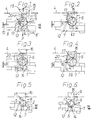
- Figur 1
- eine Schnittansicht durch die Achse des Koppelelements in der nicht verschlossenen Normalstellung,
- Figur 2
- eine Figur 1 entsprechende Ansicht bei zentralverriegeltem Schloß,
- Figur 3
- eine Figur 1 entsprechende Ansicht bei von einem Schlüssel verriegeltem Schloß,
- Figur 4
- eine Figur 1 entsprechende Ansicht bei zentralverriegeltem und von dem Schlüssel verriegeltem Schloß,
- Figur 5
- eine Figur 1 entsprechende Ansicht des zentralverriegelten Schlosses in der Betätigungslage des Übertragungselements und
- Figur 6
- eine Figur 5 entsprechende Ansicht von dem in eine Notentriegelungslage gedrehten Übertragungselement.
Claims (9)
- Schloß, insbesondere Handschuhkastenschloß eines Kraftfahrzeugs, mit einem verstellbaren Übertagungselement, das von einer äußeren Handhabe etwa senkrecht zur Längsachse des Übertragungselements verlagerbar ist und nur dann bei seiner Verlagerung mit einem Entriegelungselement des Schlosses entriegelnd zusammenwirken kann, wenn das Übertragungselement von einer Verstelleinrichtung aus einer Leerhublage in eine Betätigungslage verstellt ist, dadurch gekennzeichnet, daß zwischen dem Übertragungselement (2) und dem Entriegelungselement (6) ein Koppelelement (7) verstellbar angeordnet ist, das eine Anlagefläche (13) und eine Mitnehmerfläche (11) aufweist, und bei einer Verlagerung des Übertragungselements (2) aus seiner Betätigungslage ein Mitnehmer (5) des Übertragungselements (2) mit der Anlagefläche (13) zusammenwirkend das Koppelelement (7) verlagert, das dabei über seine Mitnehmerfläche (11) das Entriegelungselement (6) in eine das Schloß entriegelnde Lage verstellt, und bei einer Verlagerung des Übertragungselements (2) aus der Entkopplungslage der Mitnehmer (5) an der Anlagefläche (13) des Koppelelements (7) vorbei einen Leerhub ausführt.
- Schloß nach Anspruch 1, dadurch gekennzeichnet, daß eine Zentralverriegelungseinrichtung ein Zentralverriegelungselement (16) aufweist, das bei seiner Verlagerung aus einer Zentralentriegelungsstellung in eine Zentralverriegelungsstellung mit einer Stützschulter (17) an dem Koppelelement (7) zusammenwirkt und dabei das Koppelelement (7) aus einer Kopplungslage in eine Entkopplungslage verstellt und in der Entkopplungslage hält, in der ein Zusammenwirken des Mitnehmers (5) mit der Anlagefläche (13) nicht möglich ist.
- Schloß nach Anspruch 1 oder 2, dadurch gekennzeichnet, daß das Koppelelement (7) von einer Feder (10) zu dem Entriegelungselement (6) belastet ist, das von einem der Feder (10) entgegenwirkenden stärkeren Federelement in einer Normallage festgehalten ist.
- Schloß nach einem der Ansprüche 1 bis 3, dadurch gekennzeichnet, daß das Übertragungselement (2) von einem schlüsselbetätigbaren Schließzylinder von der Leerhublage in die Betätigungslage und umgekehrt verdrehbar ist.
- Schloß nach einem der Ansprüche 1 bis 4, das an dem Handschuhkasten eines Kraftfahrzeugs mit Zentralverriegelungseinrichtung vorgesehen ist, dadurch gekennzeichnet, daß das Übertragungselement (2) oder ein damit verbundenes Teil ein Betätigungselement (Schaltnase 19) aufweist, das in der Leerhublage einen Schalter (20) der mit einer Heckklappen-Verriegelungseinrichtung in Verbindung stehenden Zentralverriegelungseinrichtung betätigt, die dadurch so geschaltet wird, daß sich die Heckklappe über die Zentralverriegelungseinrichtung nicht öffnen läßt.
- Schloß nach einem der Ansprüche 1 bis 5, dadurch gekennzeichnet, daß die Anlagefläche (13) durch eine zur Verlagerungsrichtung (Pfeilrichtung 3) des Übertragungselements (2) geneigte Wand (12) an dem Koppelelement (7) gebildet ist.
- Schloß nach einem der Ansprüche 4 bis 6, dadurch gekennzeichnet, daß an dem Koppelelement (7) ein Notentriegelungssteg (14) ausgebildet ist, und das Übertragungselement (2) in der Entkopplungslage des Koppelelements (7) in eine Notentriegelungslage verdrehbar ist und dabei mit dem Notentriegelungssteg (14) zusammenwirkend das Koppelelement (7) zwangsweise in die Kopplungslage verstellt.
- Schloß nach Anspruch 7, dadurch gekennzeichnet, daß bei der Verlagerung des Koppelelements (7) in die Kopplungslage das Koppelelement (7) an dem Zentralverriegelungselement (16) zur Anlage kommt und bei seiner weiteren Bewegung in die Kopplungslage das Zentralverriegelungselement (16) in die Zentralentriegelungsstellung verstellt.
- Schloß nach Anspruch 7 oder 8, dadurch gekennzeichnet, daß beim schlüsselbetätigten Zurückstellen des Übertragungselements (2) aus der Notentriegelungslage in die Kopplungslage oder in die Entkopplungslage das Übertragungselement (2) kurzzeitig das Koppelelement (7) gegen die Kraft der Feder (10) in Richtung der Entkopplungslage verstellt, wenn sich im Verstellbereich des Übertragungselements (2) ein Bereich (Wand 12) des Koppelelements (7) befindet.
Applications Claiming Priority (2)
| Application Number | Priority Date | Filing Date | Title |
|---|---|---|---|
| DE19831727 | 1998-07-15 | ||
| DE19831727A DE19831727C2 (de) | 1998-07-15 | 1998-07-15 | Schloß, insbesondere Handschuhkastenschloß eines Kraftfahrzeugs |
Publications (2)
| Publication Number | Publication Date |
|---|---|
| EP0976900A1 true EP0976900A1 (de) | 2000-02-02 |
| EP0976900B1 EP0976900B1 (de) | 2004-01-02 |
Family
ID=7874119
Family Applications (1)
| Application Number | Title | Priority Date | Filing Date |
|---|---|---|---|
| EP99112675A Expired - Lifetime EP0976900B1 (de) | 1998-07-15 | 1999-07-02 | Schloss, insbesondere Handschuhkastenschloss eines Kraftfahrzeuges |
Country Status (2)
| Country | Link |
|---|---|
| EP (1) | EP0976900B1 (de) |
| DE (2) | DE19831727C2 (de) |
Cited By (2)
| Publication number | Priority date | Publication date | Assignee | Title |
|---|---|---|---|---|
| WO2002046557A3 (de) * | 2000-12-07 | 2003-01-23 | Witte Strattec Llc | Schloss mit von einer sperrklinke in einer geschlossen-stellung gehaltenen falle |
| US7603881B2 (en) | 2005-11-24 | 2009-10-20 | Kabushiki Kaisha Honda Lock | Glove box device |
Families Citing this family (3)
| Publication number | Priority date | Publication date | Assignee | Title |
|---|---|---|---|---|
| JP3940318B2 (ja) | 2002-06-03 | 2007-07-04 | 株式会社パイオラックス | サイドロック装置 |
| KR100622727B1 (ko) * | 2004-03-31 | 2006-09-14 | 현대자동차주식회사 | 자동차용 트렁크리드 래치어셈블리 |
| DE102004042419A1 (de) * | 2004-09-02 | 2006-03-30 | Daimlerchrysler Ag | Verriegelungsvorrichtung für einen Klappdeckel |
Citations (5)
| Publication number | Priority date | Publication date | Assignee | Title |
|---|---|---|---|---|
| DE3504806A1 (de) * | 1985-02-13 | 1986-09-18 | Metallwarenfabrik Karl Simon Gmbh & Co Kg, 7234 Aichhalden | Schloss mit gehaeuse und darin verstellbarem schubriegel |
| EP0258582A2 (de) * | 1986-08-30 | 1988-03-09 | VDO Adolf Schindling AG | Elektromotorisches Stellelement für eine Zentralverriegelungsanlage von Kraftfahrzeugen |
| DE4114988A1 (de) * | 1991-05-08 | 1992-11-12 | Vdo Schindling | Tuerschloss |
| EP0633376A1 (de) * | 1993-07-08 | 1995-01-11 | Mauer GmbH | Elektromagnetisch gesteuertes Sperrschloss |
| DE4407522C1 (de) * | 1994-03-07 | 1995-06-22 | Bayerische Motoren Werke Ag | Verriegelungsvorrichtung für einen schwenkbar gelagerten Aufbewahrungsbehälter in einem Fahrzeug |
Family Cites Families (2)
| Publication number | Priority date | Publication date | Assignee | Title |
|---|---|---|---|---|
| DE2617802C3 (de) * | 1976-04-23 | 1980-07-03 | Bayerische Motoren Werke Ag, 8000 Muenchen | Verriegelungsvorrichtung in Verbindung mit einer Zentralverriegelungsanlage für schwenkbare Teile eines Kraftfahrzeugs |
| DE4408910A1 (de) * | 1994-03-16 | 1995-09-21 | Huelsbeck & Fuerst | Verschlußvorrichtung mit einem zugleich als Druckhandhabe zum Betätigen von Schloßgliedern dienenden Schließzylinder |
-
1998
- 1998-07-15 DE DE19831727A patent/DE19831727C2/de not_active Expired - Fee Related
-
1999
- 1999-07-02 DE DE59908186T patent/DE59908186D1/de not_active Expired - Fee Related
- 1999-07-02 EP EP99112675A patent/EP0976900B1/de not_active Expired - Lifetime
Patent Citations (5)
| Publication number | Priority date | Publication date | Assignee | Title |
|---|---|---|---|---|
| DE3504806A1 (de) * | 1985-02-13 | 1986-09-18 | Metallwarenfabrik Karl Simon Gmbh & Co Kg, 7234 Aichhalden | Schloss mit gehaeuse und darin verstellbarem schubriegel |
| EP0258582A2 (de) * | 1986-08-30 | 1988-03-09 | VDO Adolf Schindling AG | Elektromotorisches Stellelement für eine Zentralverriegelungsanlage von Kraftfahrzeugen |
| DE4114988A1 (de) * | 1991-05-08 | 1992-11-12 | Vdo Schindling | Tuerschloss |
| EP0633376A1 (de) * | 1993-07-08 | 1995-01-11 | Mauer GmbH | Elektromagnetisch gesteuertes Sperrschloss |
| DE4407522C1 (de) * | 1994-03-07 | 1995-06-22 | Bayerische Motoren Werke Ag | Verriegelungsvorrichtung für einen schwenkbar gelagerten Aufbewahrungsbehälter in einem Fahrzeug |
Cited By (2)
| Publication number | Priority date | Publication date | Assignee | Title |
|---|---|---|---|---|
| WO2002046557A3 (de) * | 2000-12-07 | 2003-01-23 | Witte Strattec Llc | Schloss mit von einer sperrklinke in einer geschlossen-stellung gehaltenen falle |
| US7603881B2 (en) | 2005-11-24 | 2009-10-20 | Kabushiki Kaisha Honda Lock | Glove box device |
Also Published As
| Publication number | Publication date |
|---|---|
| DE19831727C2 (de) | 2000-06-15 |
| EP0976900B1 (de) | 2004-01-02 |
| DE19831727A1 (de) | 2000-01-20 |
| DE59908186D1 (de) | 2004-02-05 |
Similar Documents
| Publication | Publication Date | Title |
|---|---|---|
| DE2601149C3 (de) | Verschluß für den Kofferraum eines Kraftfahrzeuges | |
| DE8915994U1 (de) | Kraftfahrzeugtürverschluß mit einem Zentralverriegelungsantrieb | |
| DE102020208733A1 (de) | Bidirektionale türöffnungsstruktur | |
| EP3016844B1 (de) | Schliessbaugruppe für einen gepäckkoffer | |
| DE10158221A1 (de) | Schließsystem mit einer Funktionssteuerungsmechanik | |
| DE4325693C2 (de) | Türschließeinrichtung | |
| DE3743282C2 (de) | ||
| DE3626441C1 (en) | Motor-vehicle door lock | |
| DE102004062758B4 (de) | Kofferraumdeckelverriegelungseinheit für ein Fahrzeug | |
| DE3728960C1 (de) | Abschliessbarer Handschuhkastendeckel fuer Kraftwagen | |
| DE2829770C2 (de) | Türschloßstellantrieb für Kraftfahrzeuge | |
| DE19821752A1 (de) | Verriegelungsvorrichtung für eine Kraftfahrzeugtür | |
| DE10163611A1 (de) | Entriegelungsvorrichtung für einen Fahrzeugsitz | |
| EP0976900A1 (de) | Schloss, insbesondere Handschuhkastenschloss eines Kraftfahrzeuges | |
| DE2911680A1 (de) | Kraftfahrzeugtuerverschluss | |
| DE2261029B2 (de) | SchnallenschloB | |
| DE4108507C2 (de) | Kraftfahrzeugtürverschluß mit Zentralverriegelungsantrieb | |
| EP1725725B1 (de) | Kraftfahrzeug mit einer zentralverriegelung | |
| DE3006151A1 (de) | Schloss, insbesondere fuer kraftfahrzeug-heckklappentuer | |
| DE69612558T2 (de) | Schliessvorrichtung für handschuhfachdeckel | |
| EP0392070B1 (de) | Zentralverriegelungsanlage | |
| DE3717940C2 (de) | ||
| DE102005047731A1 (de) | Verriegelungseinrichtung für Kraftfahrzeugsitze | |
| DE3732739A1 (de) | Vorrichtung zur blockierung der schwenkbaren rueckenlehne eines kraftfahrzeugsitzes | |
| DE1198236B (de) | Bedienungseinrichtung fuer hydraulisch wirkende Schwenk- und Schliessvorrichtung von schwenkbaren Klappen od. dgl. an Kraftfahrzeugen |
Legal Events
| Date | Code | Title | Description |
|---|---|---|---|
| PUAI | Public reference made under article 153(3) epc to a published international application that has entered the european phase |
Free format text: ORIGINAL CODE: 0009012 |
|
| AK | Designated contracting states |
Kind code of ref document: A1 Designated state(s): DE FR GB |
|
| AX | Request for extension of the european patent |
Free format text: AL;LT;LV;MK;RO;SI |
|
| 17P | Request for examination filed |
Effective date: 20000714 |
|
| AKX | Designation fees paid |
Free format text: DE FR GB |
|
| 17Q | First examination report despatched |
Effective date: 20010511 |
|
| GRAP | Despatch of communication of intention to grant a patent |
Free format text: ORIGINAL CODE: EPIDOSNIGR1 |
|
| GRAS | Grant fee paid |
Free format text: ORIGINAL CODE: EPIDOSNIGR3 |
|
| GRAA | (expected) grant |
Free format text: ORIGINAL CODE: 0009210 |
|
| AK | Designated contracting states |
Kind code of ref document: B1 Designated state(s): DE FR GB |
|
| REG | Reference to a national code |
Ref country code: GB Ref legal event code: FG4D Free format text: NOT ENGLISH |
|
| GBT | Gb: translation of ep patent filed (gb section 77(6)(a)/1977) |
Effective date: 20040102 |
|
| REF | Corresponds to: |
Ref document number: 59908186 Country of ref document: DE Date of ref document: 20040205 Kind code of ref document: P |
|
| ET | Fr: translation filed | ||
| PLBE | No opposition filed within time limit |
Free format text: ORIGINAL CODE: 0009261 |
|
| STAA | Information on the status of an ep patent application or granted ep patent |
Free format text: STATUS: NO OPPOSITION FILED WITHIN TIME LIMIT |
|
| 26N | No opposition filed |
Effective date: 20041005 |
|
| PGFP | Annual fee paid to national office [announced via postgrant information from national office to epo] |
Ref country code: FR Payment date: 20050728 Year of fee payment: 7 |
|
| PGFP | Annual fee paid to national office [announced via postgrant information from national office to epo] |
Ref country code: GB Payment date: 20060727 Year of fee payment: 8 |
|
| PGFP | Annual fee paid to national office [announced via postgrant information from national office to epo] |
Ref country code: DE Payment date: 20060830 Year of fee payment: 8 |
|
| GBPC | Gb: european patent ceased through non-payment of renewal fee |
Effective date: 20070702 |
|
| PG25 | Lapsed in a contracting state [announced via postgrant information from national office to epo] |
Ref country code: DE Free format text: LAPSE BECAUSE OF NON-PAYMENT OF DUE FEES Effective date: 20080201 |
|
| PG25 | Lapsed in a contracting state [announced via postgrant information from national office to epo] |
Ref country code: GB Free format text: LAPSE BECAUSE OF NON-PAYMENT OF DUE FEES Effective date: 20070702 |
|
| REG | Reference to a national code |
Ref country code: FR Ref legal event code: ST Effective date: 20080331 |
|
| PG25 | Lapsed in a contracting state [announced via postgrant information from national office to epo] |
Ref country code: FR Free format text: LAPSE BECAUSE OF NON-PAYMENT OF DUE FEES Effective date: 20070731 |
|
| PG25 | Lapsed in a contracting state [announced via postgrant information from national office to epo] |
Ref country code: FR Free format text: LAPSE BECAUSE OF NON-PAYMENT OF DUE FEES Effective date: 20060731 |