EP0976972B1 - Drehknopf eines Steuergerätes - Google Patents
Drehknopf eines Steuergerätes Download PDFInfo
- Publication number
- EP0976972B1 EP0976972B1 EP99107613A EP99107613A EP0976972B1 EP 0976972 B1 EP0976972 B1 EP 0976972B1 EP 99107613 A EP99107613 A EP 99107613A EP 99107613 A EP99107613 A EP 99107613A EP 0976972 B1 EP0976972 B1 EP 0976972B1
- Authority
- EP
- European Patent Office
- Prior art keywords
- light
- rotary knob
- conducting element
- scale
- rotary
- Prior art date
- Legal status (The legal status is an assumption and is not a legal conclusion. Google has not performed a legal analysis and makes no representation as to the accuracy of the status listed.)
- Expired - Lifetime
Links
- 238000000149 argon plasma sintering Methods 0.000 claims description 2
- 239000002245 particle Substances 0.000 claims description 2
- 238000005286 illumination Methods 0.000 description 5
- 230000002093 peripheral effect Effects 0.000 description 4
- 238000004519 manufacturing process Methods 0.000 description 2
- 238000004378 air conditioning Methods 0.000 description 1
- 238000010276 construction Methods 0.000 description 1
- 238000011161 development Methods 0.000 description 1
- 230000018109 developmental process Effects 0.000 description 1
Images
Classifications
-
- G—PHYSICS
- G02—OPTICS
- G02B—OPTICAL ELEMENTS, SYSTEMS OR APPARATUS
- G02B6/00—Light guides; Structural details of arrangements comprising light guides and other optical elements, e.g. couplings
- G02B6/0001—Light guides; Structural details of arrangements comprising light guides and other optical elements, e.g. couplings specially adapted for lighting devices or systems
- G02B6/0011—Light guides; Structural details of arrangements comprising light guides and other optical elements, e.g. couplings specially adapted for lighting devices or systems the light guides being planar or of plate-like form
- G02B6/0033—Means for improving the coupling-out of light from the light guide
-
- G—PHYSICS
- G05—CONTROLLING; REGULATING
- G05G—CONTROL DEVICES OR SYSTEMS INSOFAR AS CHARACTERISED BY MECHANICAL FEATURES ONLY
- G05G1/00—Controlling members, e.g. knobs or handles; Assemblies or arrangements thereof; Indicating position of controlling members
- G05G1/08—Controlling members for hand actuation by rotary movement, e.g. hand wheels
- G05G1/10—Details, e.g. of discs, knobs, wheels or handles
- G05G1/105—Details, e.g. of discs, knobs, wheels or handles comprising arrangements for illumination
-
- H—ELECTRICITY
- H01—ELECTRIC ELEMENTS
- H01H—ELECTRIC SWITCHES; RELAYS; SELECTORS; EMERGENCY PROTECTIVE DEVICES
- H01H19/00—Switches operated by an operating part which is rotatable about a longitudinal axis thereof and which is acted upon directly by a solid body external to the switch, e.g. by a hand
- H01H19/02—Details
- H01H19/025—Light-emitting indicators
-
- H—ELECTRICITY
- H01—ELECTRIC ELEMENTS
- H01H—ELECTRIC SWITCHES; RELAYS; SELECTORS; EMERGENCY PROTECTIVE DEVICES
- H01H2219/00—Legends
- H01H2219/054—Optical elements
- H01H2219/06—Reflector
-
- H—ELECTRICITY
- H01—ELECTRIC ELEMENTS
- H01H—ELECTRIC SWITCHES; RELAYS; SELECTORS; EMERGENCY PROTECTIVE DEVICES
- H01H2219/00—Legends
- H01H2219/054—Optical elements
- H01H2219/062—Light conductor
-
- H—ELECTRICITY
- H01—ELECTRIC ELEMENTS
- H01H—ELECTRIC SWITCHES; RELAYS; SELECTORS; EMERGENCY PROTECTIVE DEVICES
- H01H2219/00—Legends
- H01H2219/054—Optical elements
- H01H2219/062—Light conductor
- H01H2219/0622—Light conductor only an illuminated ring around keys
-
- H—ELECTRICITY
- H01—ELECTRIC ELEMENTS
- H01H—ELECTRIC SWITCHES; RELAYS; SELECTORS; EMERGENCY PROTECTIVE DEVICES
- H01H9/00—Details of switching devices, not covered by groups H01H1/00 - H01H7/00
- H01H9/18—Distinguishing marks on switches, e.g. for indicating switch location in the dark; Adaptation of switches to receive distinguishing marks
- H01H9/182—Illumination of the symbols or distinguishing marks
-
- Y—GENERAL TAGGING OF NEW TECHNOLOGICAL DEVELOPMENTS; GENERAL TAGGING OF CROSS-SECTIONAL TECHNOLOGIES SPANNING OVER SEVERAL SECTIONS OF THE IPC; TECHNICAL SUBJECTS COVERED BY FORMER USPC CROSS-REFERENCE ART COLLECTIONS [XRACs] AND DIGESTS
- Y10—TECHNICAL SUBJECTS COVERED BY FORMER USPC
- Y10S—TECHNICAL SUBJECTS COVERED BY FORMER USPC CROSS-REFERENCE ART COLLECTIONS [XRACs] AND DIGESTS
- Y10S116/00—Signals and indicators
- Y10S116/36—Illuminated dial and pointer
Definitions
- the invention relates to a rotary knob of a control device according to the preamble of the claim 1.
- Such a device is known for example in DE 35 35 881 C2 and has an illumination device there, which is formed by a plurality of light guides and indicates the position of a rotary knob by appropriate illumination of a scale.
- a generic rotary knob is known from US 5,093,764. This has an illumination device, which consists of a light source and two light guide bodies. The light source is arranged off-center of the center of rotation of the rotary knob.
- This device is particularly intended for use in motor vehicles. By twisting however, the light guide experiences a loss of light when the rotary knob is adjusted Lighting device is very complicated.
- a rotating bear Operating button can be removed, which has a light guide, in the center of rotation a light entry surface is formed, in front of which a light source is arranged, wherein the light guide body ends with its peripheral part in a transparent housing part that has a scale visible from the outside. Between the peripheral part of the light guide Rotary knob and the scale there is a housing-fixed light guide body in its light path has a total reflection surface in which the light rays are deflected.
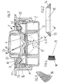
- Fig. 1 shows a section through an inventive knob 1 of a control unit 2 with electrical / electronic components 3 and a lighting device 4, which a light source 5 in front of a first light guide body 6 located in the rotary knob 1 with a in the light entry surface 7 arranged in the center of rotation, the first light guide body 6 ends with its peripheral part 8 in a transparent housing part 9, one from the outside visible scale 10 and a housing-fixed, between scale 10 and peripheral part 8 of Light guide body 6 of the rotary knob 1 arranged second light guide body 11, the has a total reflection surface 13 in its light path 12 (arrow).
- the total reflection surface 13 with its outer Page 14 forms a jacket of a truncated cone or dome 15 on which 90 ° segmented prisms 16 are arranged, d. H. the prisms 16 point with their Longitudinal center towards the fulcrum of the rotary knob 1.
- Fig. 4 shows a plan view of the ring, from which also the segment-shaped 90 ° prisms of the outer side 14 are recognizable.
- the reflection surface 13 is assigned to the scale level in such a way that the truncated cone or dome 15 lies, for example, within a 90 ° angle 17, as shown in Fig. 2, or is tuned so that a certain light exit beam results from the second light guide body 11.
- the first light guide body 6 of the rotary knob 1 has a light exit area 18, which has a light exit beam (arrow) in the direction of a translucent Area 19 with a pointer marking 20 in the rotary knob 1, as in FIG. 1 is visible.
- the two light guide bodies 6, 11 contain light-scattering particles. There is a production for this of the two light guide bodies 6, 11 made of Plexi df from Röhm.
- the inventive design of the rotary knob 1 and its lighting device 4 enable the use of the rotary knob 1 on control units 2, which are used as control units for radios, Air conditioning systems etc. are used in motor vehicles.
Landscapes
- Physics & Mathematics (AREA)
- General Physics & Mathematics (AREA)
- Engineering & Computer Science (AREA)
- Automation & Control Theory (AREA)
- Optics & Photonics (AREA)
- Rotary Switch, Piano Key Switch, And Lever Switch (AREA)
- Mechanical Control Devices (AREA)
- Switch Cases, Indication, And Locking (AREA)
- Arrangements Of Lighting Devices For Vehicle Interiors, Mounting And Supporting Thereof, Circuits Therefore (AREA)
Description
Ein gattungsgemäßer Drehknopf ist aus der US 5,093, 764 bekannt. Dieser weist eine Beleuchtungseinrichtung auf, die aus einer Lichtquelle und zwei Lichtleitkörpern besteht. Die Lichtquelle ist dabei außermittig der Drehmitte des Drehknopfes angeordnet.
einen Schnitt durch einen erfindungsgemäßen Drehknopf,
eine Einzelheit aus Fig. 1 in Schnittdarstellung,
eine Ansicht aus Fig. 2 und 3.
Claims (4)
- Drehknopf (1) für ein Steuergerät mit elektrischen/elektronischen Bauteilen (3) und einer Beleuchtungseinrichtung (4), die aus einer Lichtquelle (5) gebildet ist, die im montierten Zustand vor einem im Drehknopf (1) befindlichen ersten Lichtleitkörper (6) mit einer Lichteintrittsfläche (7) angeordnet ist, wobei der erste, Lichtleitkörper (6) mit seinem Umfangsteil (8) in einem transparenten Gehäuseteil (9) des Drehknopfes endet, das eine von außen sichtbare Skala (10) und einen gehäusefesten, zwischen Skala (10) und Umfangsteil (8) des ersten Lichtleitkörpers (6) des Drehknopfes (1) angeordneten zweiten Lichtleitkörpers (11) aufweist, dadurch gekennzeichnet, daßdie Lichteintrittsfläche (7) des ersten Lichtleitkörpers (6) in der Drehmitte des Drehknopfes angeordnet ist,der zweite Lichtleiterkörper (11) in seinem Lichtgang eine Totalreflexionsfläche (13) aufweist, wobeidie Totalreflexionsfläche (13) mit ihrer außenliegenden Seite (14) einen Mantel eines Kegel- oder Kalottenstumpfes (15) bildet, auf dem segmentförmig 90° Prismen (16) angeordnet sind.
- Drehknopf nach Anspruch 1, dadurch gekennzeichnet, daß der Kegel- oder Kalottenstumpf (15) innerhalb eines in bezug auf einen vorgegebenen Lichtaustrittsstrahl aus dem zweiten Lichtleitkörper (11) abgestimmten Winkels (17) liegt.
- Drehknopf nach Anspruch 1 oder 2, dadurch gekennzeichnet, daß der erste Lichtleitkörper (6) des Drehknopfes (1) einen Lichtaustrittsbereich (18) aufweist, der einen Lichtaustrittsstrahl (Pfeil) in Richtung auf einen lichtdurchlässigen Bereich (19) mit einer Zeigermarkierung (20) im Drehknopf (1) bewirkt.
- Drehknopf nach einem der vorstehenden Ansprüche, dadurch gekennzeichnet, daß beide Lichtleitkörper (6, 11) lichtstreuende Partikel enthalten.
Applications Claiming Priority (2)
| Application Number | Priority Date | Filing Date | Title |
|---|---|---|---|
| DE19834374 | 1998-07-30 | ||
| DE19834374A DE19834374B4 (de) | 1998-07-30 | 1998-07-30 | Drehknopf eines Steuergerätes |
Publications (3)
| Publication Number | Publication Date |
|---|---|
| EP0976972A2 EP0976972A2 (de) | 2000-02-02 |
| EP0976972A3 EP0976972A3 (de) | 2002-03-20 |
| EP0976972B1 true EP0976972B1 (de) | 2004-09-29 |
Family
ID=7875856
Family Applications (1)
| Application Number | Title | Priority Date | Filing Date |
|---|---|---|---|
| EP99107613A Expired - Lifetime EP0976972B1 (de) | 1998-07-30 | 1999-04-16 | Drehknopf eines Steuergerätes |
Country Status (4)
| Country | Link |
|---|---|
| US (1) | US6224221B1 (de) |
| EP (1) | EP0976972B1 (de) |
| JP (1) | JP2000057870A (de) |
| DE (2) | DE19834374B4 (de) |
Families Citing this family (69)
| Publication number | Priority date | Publication date | Assignee | Title |
|---|---|---|---|---|
| DE19915990C1 (de) * | 1999-04-09 | 2000-05-25 | Preh Elektro Feinmechanik | Bedienteil für Steuerungsfunktionen |
| DE19964133A1 (de) | 1999-11-22 | 2001-06-13 | Preh Elektro Feinmechanik | Drehschalter |
| US6585385B2 (en) * | 2000-06-29 | 2003-07-01 | Calsonic Kansei Corporation | Automotive meter with internal illumination structure |
| DE10044901A1 (de) * | 2000-09-12 | 2002-04-25 | Behr Hella Thermocontrol Gmbh | Bedieneinheit für eine Fahrzeugkomponente, insbesondere für eine Fahrzeug-Klimaanlage |
| DE10062931B4 (de) * | 2000-12-16 | 2005-02-10 | Siemens Ag | Drehknopf |
| DE10063875A1 (de) * | 2000-12-21 | 2002-07-04 | Siemens Ag | Anzeigeinstrument |
| DE10064759A1 (de) * | 2000-12-22 | 2002-07-04 | Siemens Ag | Zifferblatt |
| US6565223B2 (en) * | 2001-01-24 | 2003-05-20 | Visteon Global Technologies, Inc. | Integrated light transfer structure for providing halo and end illumination for a control switch assembly |
| DE10127211B4 (de) * | 2001-06-05 | 2006-10-19 | Siemens Ag | Beleuchtbare Bedieneinheit, insbesondere für Kraftfahrzeugklimaanlagen |
| DE20110812U1 (de) | 2001-06-29 | 2001-10-04 | Dr. Franz Schneider Kunststoffwerke GmbH & Co. KG, 96317 Kronach | Stellrad mit mechanischen Kopplungseinrichtungen zur Herstellung einer Wirkverbindung mit Funktionselementen und elektrischen Steuerelementen |
| DE10134395B4 (de) * | 2001-07-14 | 2009-11-12 | Grundig Multimedia B.V. | Dreh-Stelleinrichtung |
| WO2003058659A1 (de) * | 2002-01-08 | 2003-07-17 | BSH Bosch und Siemens Hausgeräte GmbH | Bedienanordnung für ein haushaltsgerät, bedienelement sowie haushaltsgerät |
| US6860224B2 (en) * | 2002-02-08 | 2005-03-01 | Delphi Technologies, Inc. | Indicator knob with overmolded applique |
| DE10236935A1 (de) * | 2002-08-12 | 2004-02-26 | BSH Bosch und Siemens Hausgeräte GmbH | Drehschalter für Haushaltsgeräte |
| DE10243629A1 (de) * | 2002-09-19 | 2004-04-08 | Electrolux Home Products Corporation N.V. | Drehknebel, insbesondere versenkbarer Drehknebel für Haushaltsgeräte |
| DE10255480B3 (de) * | 2002-11-28 | 2004-03-04 | Preh-Werke Gmbh & Co. Kg | Bedienelement |
| DE10323542B4 (de) | 2003-05-24 | 2007-08-30 | Preh Gmbh | Drehknopf eines Bediengerätes |
| DE102005032508B4 (de) * | 2004-07-15 | 2021-05-20 | BSH Hausgeräte GmbH | Bedienelement mit Leuchtquelle |
| JP4383306B2 (ja) * | 2004-10-05 | 2009-12-16 | アルプス電気株式会社 | 照光装置 |
| DE102004052572B4 (de) * | 2004-10-29 | 2008-06-12 | Electrolux Home Products Corp. N.V. | Bedienungseinrichtung für ein Haushaltsgerät |
| JP2006147498A (ja) * | 2004-11-24 | 2006-06-08 | Konica Minolta Business Technologies Inc | 押下釦 |
| FR2884931B1 (fr) * | 2005-04-25 | 2007-07-06 | Valeo Systemes Thermiques | Guide de lumiere d'un bouton de commande equipe d'un index rotatif |
| FR2889767B1 (fr) * | 2005-08-11 | 2011-05-13 | Valeo Systemes Thermiques | Retro eclairage d'un bouton de commande avec guide lumiere. |
| US7222979B1 (en) * | 2005-11-09 | 2007-05-29 | Cfm Corporation | Illuminated dial |
| JP2007163690A (ja) * | 2005-12-12 | 2007-06-28 | Canon Inc | 表示装置及び該表示装置を用いる装置 |
| US20070253185A1 (en) * | 2006-05-01 | 2007-11-01 | Anibal Palacio | Method and system for illuminating an indicator |
| JP4714098B2 (ja) * | 2006-07-06 | 2011-06-29 | 株式会社東海理化電機製作所 | 照明装置 |
| US20080060921A1 (en) * | 2006-09-12 | 2008-03-13 | Motorola, Inc. | Keypad for an electronic device |
| CN101377983B (zh) * | 2007-08-29 | 2012-03-14 | 博西华电器(江苏)有限公司 | 家用电器操作装置和指示单元操作方法 |
| JP5045755B2 (ja) * | 2007-08-30 | 2012-10-10 | 富士通株式会社 | キー操作部の照光構造、電子装置、携帯装置、及びキー操作部の照光方法 |
| DE102007044360A1 (de) | 2007-09-17 | 2009-03-19 | Robert Bosch Gmbh | Verbesserte Beleuchtung für Stellknopf eines Anzeigeinstruments |
| JP4985444B2 (ja) * | 2008-02-12 | 2012-07-25 | 住友電装株式会社 | 照明機能を有する操作装置 |
| ITBO20080061U1 (it) * | 2008-08-05 | 2010-02-06 | Alberici S P A | Punsante luminoso |
| DE102009006434B3 (de) * | 2009-01-22 | 2010-06-17 | E.G.O. Elektro-Gerätebau GmbH | Bedieneinrichtung für ein Elektrogerät und Bedienblende |
| DE102009006421A1 (de) * | 2009-01-22 | 2010-07-29 | E.G.O. Elektro-Gerätebau GmbH | Bedieneinrichtung für ein Elektrogerät |
| JP5136488B2 (ja) * | 2009-03-24 | 2013-02-06 | 住友電装株式会社 | 回転摘み |
| JP5297854B2 (ja) * | 2009-03-25 | 2013-09-25 | スタンレー電気株式会社 | 照明装置 |
| JP5201094B2 (ja) * | 2009-06-30 | 2013-06-05 | 住友電装株式会社 | 回転摘み |
| EP2339602B1 (de) * | 2009-11-06 | 2013-05-22 | RAFI GmbH & Co. KG | Schaltvorrichtung mit Reflektor |
| ES2376447B1 (es) * | 2010-01-08 | 2013-01-29 | Fagor, S. Coop. | Dispositivo de control iluminable adaptado a un panel de mandos de un aparato electrodoméstico. |
| WO2011090844A1 (en) * | 2010-01-21 | 2011-07-28 | Illinois Tool Works Inc. | Light ring for appliance control adjustable for console thickness |
| DE102010001653A1 (de) * | 2010-02-08 | 2011-08-11 | ZF Friedrichshafen AG, 88046 | Beleuchtbare Tastatur |
| JP2011165523A (ja) * | 2010-02-10 | 2011-08-25 | Sony Corp | 周囲発光型ボタン装置及び電子機器 |
| JP2011181327A (ja) * | 2010-03-01 | 2011-09-15 | Sumitomo Wiring Syst Ltd | 操作装置 |
| FR2957692B1 (fr) * | 2010-03-17 | 2012-06-08 | Delphi Tech Inc | Dispositif de commande a commutateur rotatif retro-eclaire par un guide de lumiere |
| US8813676B2 (en) * | 2010-05-07 | 2014-08-26 | Whirlpool Corporation | User interface for a controller |
| WO2012042848A1 (ja) * | 2010-09-29 | 2012-04-05 | パナソニック株式会社 | 電子機器 |
| US8979289B2 (en) * | 2010-12-30 | 2015-03-17 | Arcelik Anonim Sirketi | Illuminated knob for household appliance |
| JP5871669B2 (ja) * | 2012-03-13 | 2016-03-01 | アルプス電気株式会社 | 照光機能付き入力装置 |
| FR2991246B1 (fr) * | 2012-05-30 | 2015-07-17 | Continental Automotive France | Dispositif de commande avec tenue a l'arrachement |
| FR2991247B1 (fr) | 2012-05-30 | 2014-07-04 | Continental Automotive France | Dispositif de commande avec tenue a l'arrachement |
| CN102729827B (zh) * | 2012-06-25 | 2016-01-06 | 惠州市德赛西威汽车电子股份有限公司 | 一种汽车内饰旋钮结构 |
| SG2012095022A (en) * | 2012-12-21 | 2014-07-30 | Schneider Electric South East Asia Hq Pte Ltd | Visual indication for adjustable component |
| DE102013113319B3 (de) * | 2013-12-02 | 2014-11-27 | Trw Automotive Electronics & Components Gmbh | Luftausströmer |
| DE102013113725A1 (de) * | 2013-12-09 | 2015-06-11 | Bürkert Werke GmbH | Steuerkopf |
| WO2015087366A1 (ja) * | 2013-12-11 | 2015-06-18 | 東京コスモス電機株式会社 | 可動部付電子部品 |
| DE102015215769A1 (de) * | 2015-08-19 | 2017-02-23 | BSH Hausgeräte GmbH | Bedienvorrichtung für ein Haushaltsgerät mit einem Lichtleiter zur Mehrzonenbeleuchtung einer Frontkappe mit unterschiedlichen Lichtintensitäten, Haushaltsgerät mit einer derartigen Bedienvorrichtung und Verfahren zum Betreiben einer Bedienvorrichtung |
| CN106558438B (zh) * | 2015-09-29 | 2018-08-10 | 技嘉科技股份有限公司 | 按键装置及导光元件 |
| US10409314B2 (en) * | 2015-09-30 | 2019-09-10 | Haier Us Appliance Solutions, Inc. | Integrated housing for components of a cooking appliance |
| US9835789B2 (en) | 2015-10-12 | 2017-12-05 | Denso International America, Inc. | Illuminated operational device |
| US10281154B2 (en) | 2016-04-21 | 2019-05-07 | Haier Us Appliance Solutions, Inc. | Illuminated knob assembly for an appliance |
| ES2910717T3 (es) | 2016-07-04 | 2022-05-13 | Dormakaba Deutschland Gmbh | Botón de emergencia |
| FR3062221B1 (fr) * | 2017-01-20 | 2021-01-08 | Valeo Comfort & Driving Assistance | Module de commande rotatif pour habitacle de vehicule |
| US10345514B2 (en) * | 2017-02-22 | 2019-07-09 | Haier Us Appliance Solutions, Inc. | Appliance and illuminated knob assembly |
| US10139851B2 (en) * | 2017-02-24 | 2018-11-27 | Joseph Robichaud | Radio decoration system |
| WO2019144008A1 (en) * | 2018-01-19 | 2019-07-25 | Lutron Electronics Co., Inc. | Keypad having illuminated buttons |
| DE102019101264A1 (de) * | 2019-01-18 | 2020-07-23 | Eaton Intelligent Power Limited | Tastschalter-Anordnung mit Kennzeichnung eines Schaltzustandes |
| KR102823769B1 (ko) * | 2020-08-28 | 2025-06-23 | 엘지전자 주식회사 | 조리기기 및 조리기기의 노브 어셈블리 |
| TWI784542B (zh) * | 2021-05-25 | 2022-11-21 | 啓碁科技股份有限公司 | 具有光指示功能之電子裝置 |
Family Cites Families (13)
| Publication number | Priority date | Publication date | Assignee | Title |
|---|---|---|---|---|
| US1566069A (en) * | 1925-05-19 | 1925-12-15 | William C Buchholz | Illuminated dial |
| US2999148A (en) * | 1958-08-21 | 1961-09-05 | Ind Glass Corp | Variable intensity dial illuminator |
| DE2138660A1 (de) * | 1971-08-03 | 1973-03-15 | Kracht Pumpen Motoren | Steuergeraet, insbesondere fuer die betaetigung von klappen und schiebern auf tankerschiffen |
| DE2535080C2 (de) * | 1975-08-06 | 1977-12-08 | Schoeller & Co, Elektrotechnische Fabrik Gmbh & Co, 6000 Frankfurt | Beleuchtungseinrichtung für Zigarrenanzünder |
| JPS53164166U (de) * | 1977-05-30 | 1978-12-22 | ||
| US4215047A (en) * | 1977-06-06 | 1980-07-29 | Ajinomoto Company Incorporated | 7-(Arginylamino)-4-methylcoumarins |
| DE3409260A1 (de) * | 1983-10-10 | 1985-04-11 | Preh, Elektrofeinmechanische Werke Jakob Preh Nachf. Gmbh & Co, 8740 Bad Neustadt | Bedieneinheit |
| DE3535881A1 (de) * | 1985-10-08 | 1987-04-16 | Preh Elektro Feinmechanik | Beleuchtungseinrichtung fuer eine frontplatte |
| IT8653062V0 (it) * | 1986-03-03 | 1986-03-03 | Siette Spa | Ghiera luminosa per accessori di bordo di veicoli |
| JPH03127294U (de) * | 1990-04-05 | 1991-12-20 | ||
| DE4022515A1 (de) * | 1990-07-14 | 1992-01-16 | Helag Electronic Gmbh | Induktiver regler |
| US5697689A (en) * | 1993-08-09 | 1997-12-16 | General Automotive Specialty Co., Inc. | Rotary switch indicator including horseshoe light guide |
| DE19712294C2 (de) * | 1997-03-24 | 1999-08-12 | Preh Elektro Feinmechanik | Drehwiderstand |
-
1998
- 1998-07-30 DE DE19834374A patent/DE19834374B4/de not_active Expired - Fee Related
-
1999
- 1999-04-16 DE DE59910637T patent/DE59910637D1/de not_active Expired - Fee Related
- 1999-04-16 EP EP99107613A patent/EP0976972B1/de not_active Expired - Lifetime
- 1999-06-30 US US09/343,727 patent/US6224221B1/en not_active Expired - Fee Related
- 1999-07-28 JP JP11214078A patent/JP2000057870A/ja not_active Ceased
Also Published As
| Publication number | Publication date |
|---|---|
| US6224221B1 (en) | 2001-05-01 |
| EP0976972A2 (de) | 2000-02-02 |
| DE19834374B4 (de) | 2004-03-04 |
| DE19834374A1 (de) | 2000-02-03 |
| JP2000057870A (ja) | 2000-02-25 |
| EP0976972A3 (de) | 2002-03-20 |
| DE59910637D1 (de) | 2004-11-04 |
Similar Documents
| Publication | Publication Date | Title |
|---|---|---|
| EP0976972B1 (de) | Drehknopf eines Steuergerätes | |
| EP1083090B1 (de) | Lichtleiterpilz | |
| DE2925578C3 (de) | Beleuchtetes Anzeigegerät | |
| EP0900694B1 (de) | Signalleuchte für Fahrzeuge | |
| EP0818066A1 (de) | Elektrisches verbindungsteil mit kontaktstiften oder -buchsen, wie stecker oder kupplung | |
| DE3915119C1 (de) | ||
| DE4227468C2 (de) | Elektrische Schaltereinheit, insbesondere zur Steuerung von Klimaanlagen in Kraftfahrzeugen | |
| DE3300271C2 (de) | Beleuchtetes Anzeigeinstrument | |
| DE19803537A1 (de) | Leuchte für Fahrzeuge | |
| DE2035719C3 (de) | Drehknopf | |
| DE19654651A1 (de) | Beleuchtetes Rändelrad | |
| DE2908453A1 (de) | Farbiges licht abgebende signalleuchte, insbesondere fuer fahrzeuge | |
| DE3201571A1 (de) | Anzeigeeinrichtung | |
| DE2903070A1 (de) | Beleuchtetes anzeigegeraet | |
| DE3533056A1 (de) | Mehrstufiger, beleuchteter schalter an kraftfahrzeugen | |
| DE3113773C2 (de) | ||
| DE1806718B2 (de) | Beleuchtungsvorrichtung fuer eine instrumententafel in einem kraftwagen | |
| DE2144588A1 (de) | Beleuchtung fuer kontroll- oder bedienungselemente von fahrzeugen | |
| DE2750828C3 (de) | Fahrzeugleuchte | |
| DE19606179A1 (de) | Leuchtvorrichtung | |
| DE2203163C3 (de) | Beleuchtungseinrichtung für Zigarrenanzünder, insbesondere für Kraftfahrzeuge | |
| DE102012210443B4 (de) | Lichtdurchlässige Scheibe für eine Leuchte, insbesondere für eine Fahrzeugleuchte | |
| DE202004005457U1 (de) | Kabelverschraubung aus Kunststoff | |
| EP2913698B1 (de) | Lichtleitendes Bauteil sowie Feldbusmodul | |
| DE10143357A1 (de) | Starrer Lichtleiter |
Legal Events
| Date | Code | Title | Description |
|---|---|---|---|
| PUAI | Public reference made under article 153(3) epc to a published international application that has entered the european phase |
Free format text: ORIGINAL CODE: 0009012 |
|
| AK | Designated contracting states |
Kind code of ref document: A2 Designated state(s): AT BE CH CY DE DK ES FI FR GB GR IE IT LI LU MC NL PT SE Kind code of ref document: A2 Designated state(s): DE FR GB IT |
|
| AX | Request for extension of the european patent |
Free format text: AL;LT;LV;MK;RO;SI |
|
| PUAL | Search report despatched |
Free format text: ORIGINAL CODE: 0009013 |
|
| AK | Designated contracting states |
Kind code of ref document: A3 Designated state(s): AT BE CH CY DE DK ES FI FR GB GR IE IT LI LU MC NL PT SE |
|
| AX | Request for extension of the european patent |
Free format text: AL;LT;LV;MK;RO;SI |
|
| 17P | Request for examination filed |
Effective date: 20020206 |
|
| AKX | Designation fees paid |
Free format text: DE FR GB IT |
|
| 17Q | First examination report despatched |
Effective date: 20031009 |
|
| GRAP | Despatch of communication of intention to grant a patent |
Free format text: ORIGINAL CODE: EPIDOSNIGR1 |
|
| RAP1 | Party data changed (applicant data changed or rights of an application transferred) |
Owner name: PREH GMBH |
|
| GRAS | Grant fee paid |
Free format text: ORIGINAL CODE: EPIDOSNIGR3 |
|
| GRAA | (expected) grant |
Free format text: ORIGINAL CODE: 0009210 |
|
| AK | Designated contracting states |
Kind code of ref document: B1 Designated state(s): DE FR GB IT |
|
| PG25 | Lapsed in a contracting state [announced via postgrant information from national office to epo] |
Ref country code: IT Free format text: LAPSE BECAUSE OF FAILURE TO SUBMIT A TRANSLATION OF THE DESCRIPTION OR TO PAY THE FEE WITHIN THE PRESCRIBED TIME-LIMIT;WARNING: LAPSES OF ITALIAN PATENTS WITH EFFECTIVE DATE BEFORE 2007 MAY HAVE OCCURRED AT ANY TIME BEFORE 2007. THE CORRECT EFFECTIVE DATE MAY BE DIFFERENT FROM THE ONE RECORDED. Effective date: 20040929 Ref country code: GB Free format text: LAPSE BECAUSE OF FAILURE TO SUBMIT A TRANSLATION OF THE DESCRIPTION OR TO PAY THE FEE WITHIN THE PRESCRIBED TIME-LIMIT Effective date: 20040929 |
|
| REG | Reference to a national code |
Ref country code: GB Ref legal event code: FG4D Free format text: NOT ENGLISH |
|
| REG | Reference to a national code |
Ref country code: IE Ref legal event code: FG4D Free format text: GERMAN |
|
| REF | Corresponds to: |
Ref document number: 59910637 Country of ref document: DE Date of ref document: 20041104 Kind code of ref document: P |
|
| PGFP | Annual fee paid to national office [announced via postgrant information from national office to epo] |
Ref country code: FR Payment date: 20050412 Year of fee payment: 7 |
|
| REG | Reference to a national code |
Ref country code: IE Ref legal event code: FD4D |
|
| GBV | Gb: ep patent (uk) treated as always having been void in accordance with gb section 77(7)/1977 [no translation filed] |
Effective date: 20040929 |
|
| ET | Fr: translation filed | ||
| PLBE | No opposition filed within time limit |
Free format text: ORIGINAL CODE: 0009261 |
|
| STAA | Information on the status of an ep patent application or granted ep patent |
Free format text: STATUS: NO OPPOSITION FILED WITHIN TIME LIMIT |
|
| 26N | No opposition filed |
Effective date: 20050630 |
|
| REG | Reference to a national code |
Ref country code: FR Ref legal event code: ST Effective date: 20061230 |
|
| PG25 | Lapsed in a contracting state [announced via postgrant information from national office to epo] |
Ref country code: FR Free format text: LAPSE BECAUSE OF NON-PAYMENT OF DUE FEES Effective date: 20060502 |
|
| PGFP | Annual fee paid to national office [announced via postgrant information from national office to epo] |
Ref country code: DE Payment date: 20090202 Year of fee payment: 11 |
|
| PG25 | Lapsed in a contracting state [announced via postgrant information from national office to epo] |
Ref country code: DE Free format text: LAPSE BECAUSE OF NON-PAYMENT OF DUE FEES Effective date: 20101103 |