EP0976981B1 - Brennstoffzuführvorrichtung für Verbrennungsanlage - Google Patents
Brennstoffzuführvorrichtung für Verbrennungsanlage Download PDFInfo
- Publication number
- EP0976981B1 EP0976981B1 EP99112577A EP99112577A EP0976981B1 EP 0976981 B1 EP0976981 B1 EP 0976981B1 EP 99112577 A EP99112577 A EP 99112577A EP 99112577 A EP99112577 A EP 99112577A EP 0976981 B1 EP0976981 B1 EP 0976981B1
- Authority
- EP
- European Patent Office
- Prior art keywords
- guide
- charging
- appliance according
- piston
- charging appliance
- Prior art date
- Legal status (The legal status is an assumption and is not a legal conclusion. Google has not performed a legal analysis and makes no representation as to the accuracy of the status listed.)
- Expired - Lifetime
Links
- 239000000463 material Substances 0.000 title description 2
- 239000000446 fuel Substances 0.000 claims abstract description 11
- 238000002485 combustion reaction Methods 0.000 claims description 16
- 238000002309 gasification Methods 0.000 claims description 15
- 238000009434 installation Methods 0.000 claims 2
- 238000007789 sealing Methods 0.000 abstract description 10
- 239000007789 gas Substances 0.000 description 5
- 239000002893 slag Substances 0.000 description 5
- 238000004519 manufacturing process Methods 0.000 description 4
- 239000003570 air Substances 0.000 description 3
- 238000000034 method Methods 0.000 description 2
- XLYOFNOQVPJJNP-UHFFFAOYSA-N water Substances O XLYOFNOQVPJJNP-UHFFFAOYSA-N 0.000 description 2
- 230000002411 adverse Effects 0.000 description 1
- 239000012080 ambient air Substances 0.000 description 1
- 230000009286 beneficial effect Effects 0.000 description 1
- 230000000903 blocking effect Effects 0.000 description 1
- 238000004140 cleaning Methods 0.000 description 1
- 230000001419 dependent effect Effects 0.000 description 1
- 238000006073 displacement reaction Methods 0.000 description 1
- 230000000694 effects Effects 0.000 description 1
- 230000002349 favourable effect Effects 0.000 description 1
- 238000010304 firing Methods 0.000 description 1
- 230000035515 penetration Effects 0.000 description 1
- 238000007493 shaping process Methods 0.000 description 1
- 239000002341 toxic gas Substances 0.000 description 1
Images




Classifications
-
- F—MECHANICAL ENGINEERING; LIGHTING; HEATING; WEAPONS; BLASTING
- F23—COMBUSTION APPARATUS; COMBUSTION PROCESSES
- F23K—FEEDING FUEL TO COMBUSTION APPARATUS
- F23K3/00—Feeding or distributing of lump or pulverulent fuel to combustion apparatus
- F23K3/08—Feeding or distributing of lump or pulverulent fuel to combustion apparatus for furnaces having movable grate bars
-
- F—MECHANICAL ENGINEERING; LIGHTING; HEATING; WEAPONS; BLASTING
- F23—COMBUSTION APPARATUS; COMBUSTION PROCESSES
- F23G—CREMATION FURNACES; CONSUMING WASTE PRODUCTS BY COMBUSTION
- F23G2205/00—Waste feed arrangements
- F23G2205/10—Waste feed arrangements using ram or pusher
-
- F—MECHANICAL ENGINEERING; LIGHTING; HEATING; WEAPONS; BLASTING
- F23—COMBUSTION APPARATUS; COMBUSTION PROCESSES
- F23K—FEEDING FUEL TO COMBUSTION APPARATUS
- F23K2203/00—Feeding arrangements
- F23K2203/20—Feeding/conveying devices
- F23K2203/203—Feeding/conveying devices using pistons or rams
Definitions
- the invention relates to a loading device for Incineration and gasification plants where the fuel from a feed hopper via a feed table by means of at least one loading element can be introduced into the system, the loading element a thrust part for the movement of the fuel and comprises a guide part, the circular cylindrical shape has and is guided in a guide arrangement and wherein the guide part engages through a sealing arrangement.
- a loading device of this type is known from DE 29 03 199 A. known.
- this known loading device is only the Sealed guide part, so that fine parts during operation between the rectangular cross section and penetrate its adapted guide arrangement can, which can lead to a blockage of the thrust part.
- the thrust part and the guide part are circular cylindrical trained, but it is not a seal for one of the two parts provided so that this loading device neither for incineration plants nor for gasification plants can be used because an outflow of toxic gases from the Gasification system and sucking in ambient air the incinerator are undesirable.
- the loading device has a circular cylindrical thrust piston with a correspondingly designed Guide part, but there is also none Sealing provided.
- This feeder is in set up a water reservoir from the feed hopper, from which out the fuel to be fed through a tubular Chute is conveyed diagonally upwards into the kiln. There is a certain seal through the from the Burning plug formed in the feed chute and through the water reserve, however, such an arrangement is not can be used for all combustion and gasification plants, because in most cases the fuel is humidified before being sent to the incineration or gasification plant is out of the question.
- US 3 863 779 A is a loading device known, which is a square in cross-section thrust piston has in a corresponding channel by means of a guide carriage supported by rollers is guided, however, no seal is also provided here, so that this Feeder for most combustion and Gasification plants is not suitable.
- the object of the invention is to provide a loading device, through the constructive design of the loading element a simple and reliable seal, in particular in terms of gas exchange.
- This task is the beginning of a loading device explained type according to the invention solved in that the loading element overall with a cylindrical piston same diameters for the guide part and the push part is formed and that the sealing arrangement also with the thrust part cooperates.
- the push part has a surface structure has, which differs from that of the guide part.
- a such other surface structure can be machined or can be achieved by another material.
- An advantageous development of the invention consists in that the guide arrangement for the guide part two at a distance mutually arranged sets of three guide rollers each comprises, at least one of these three guide roles is adjustable radially to the guide part.
- the guide arrangement for the Guide part at least one pair of opposing Includes rollers that are rotatably mounted on the guide member and are guided in profile rails. These rails are outside provided and take the seal assembly at least one pair, preferably two pairs, facing each other Guide rollers on whose axes of rotation are vertical are arranged to the thrust piston axis and which are preferably run in U-shaped guide rails.
- the piston with its piston shirt in one guided as a guide arrangement guide cylinder is that with its front in the conveying direction of the piston End at the facing away from the combustion or gasification room Boundary wall of the feeder attached and is arranged outside the same.
- the guide arrangement two spaced apart in the guide cylinder Includes plain bearing bushes.
- the front seal can preferably be used as a wiper be trained.
- the configuration of the loading element as a hollow piston is not only with regard to the manufacture of the loading element advantageous because one draws from pipes during manufacture of such a loading element can go out, but is also a prerequisite for a further advantageous embodiment of the invention, which is that within the hollow Feeding element used a driver tube and on Piston foot is releasably connected to the loading element its front end protruding into the loading element a drive device for the reciprocating movement of the loading element attacks.
- the special advantage is that the point of application of the drive device is far can be placed in the hollow piston, so that the space required at the rear end of the loading element for the arrangement the drive device is reduced.
- the detachable Connection of the driver tube with the loading element also has the advantage that the connection between the drive device and driver tube can be made before it is inserted into the loading element. This has a favorable influence on the assembly of such a loading element.
- the advantageous embodiment is then special cheap if according to further training the invention when using a piston-cylinder drive unit these are almost completely in the retracted end position is accommodated in the driver tube. This is the space requirement behind the loading element is the least since the connection point between the drive device and the loading element be placed very close to its front end can what too large without such a drive tube Assembly problems would result.
- the thrust part of the loading element in an upwardly open guide trough of the feed table, this will relief of the guide arrangement for long displacement distances and on top of that a defined funding area ensured. It is recommended that the delivery rate of the charging element depending on one of the gasification or parameters dependent on the combustion process is. This allows the gasification process and behavior or combustion via a quantity regulation of the to be introduced Fuel are affected.
- the incinerator shown in Figure 1 includes one Firing grate 1, a loading device 2 and a combustion chamber 3 with subsequent throttle cable 4, to which further Throttle cables and units downstream of the incinerator, in particular steam generation and exhaust gas cleaning systems connect, which are not shown and explained here are.
- the furnace grate 1 comprises individual grate levels 5, of which every second with a drive designated 6 in total connected, which allows the stoking speed to be adjusted. Below the grate are both in Underwind chambers divided lengthways and crossways 7.1 to 7.5 are provided, which are separated by individual lines 8.1 to 8.5 are charged with primary air. At the end of The burned-out slag is fired with a grate Slag discharge device, in the illustrated embodiment a slag roller 9 in a slag chute 10 discharged from where the slag in a not shown Detoxifier falls.
- the loading device 2 comprises a feed hopper 11, a feed chute 12, a feed table 13 and at least a loading element 14, which in the feed chute 12 garbage sliding down over a loading edge 13 'of the Task 13 in the firebox 3 on the grate 1 pushes.
- a loading element 14 consists of a Thrust part 15 and a guide part 16. These can be different Shaping like this from the different Embodiments emerges.
- FIG. 2 to 8 consists of a total of one one-piece hollow piston, the front one of which is to be conveyed Fuel 17 in contact with the thrust part 15 and the remaining guide part is designated 16, which is also in the most advanced position 2 always remains in a guide cylinder 18, in which the guide part 16 by means of slide bearings 19th and 20 is led. With 21 and 22 seals are referred to to achieve a gas-tight seal of the loading element.
- the front seal 21 in the first Line serve as a wiper through which the thrust part 15th passes through, while the rear seal 22, which with the Guide part 16 cooperates, which has a smoother surface which provides better sealing against gases, that could either exit the combustion chamber or in the form of ambient or false air in the combustion chamber could be sucked in.
- a driver tube 23 is located within the loading element 14 provided that at the rear end 24 of the loading element 14 and thus at the piston foot facing away from the combustion chamber is releasably attached.
- a joint part 25 for fastening the piston rod 26 a drive unit 27 is provided, which in the retracted State of the loading element 14, as shown in FIG 3 emerges, almost completely in the driver tube 23 is included.
- a drive unit 27 In the pushed forward end position. 2 shows the cylinder arrangement of the drive unit 27 almost completely outside the driver tube 23.
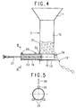
- FIGS. 4 and 5 show a modified configuration of the Guide and sealing arrangement for the loading element 14 shown.
- three are radial Directionally aligned guide rollers 29 provided by which at least one, according to Figure 5, the upper, in Direction of the double arrow 30 is adjustable.
- the feed chute 12 For sealing of the loading element 14 is on the rear wall 31 the feed chute 12 a sealingly enclosing the guide part and wall mounting seal assembly 32 provided.
- FIGS. 6 and 7 show a further embodiment for the Guide arrangement of the feed element 14 shown in the laterally arranged axial rollers 33 in one rail each 34 are performed.
- the seal 32 corresponds to that of Figure 4.
- the loading element When the loading element is designed as a piston as a whole With a circular cylindrical shape, it is necessary to use several Feeding elements 14 to be provided side by side, like this Figures 8 and 9 emerges.
- the loading elements are included in guide troughs 35.
- the loading elements can - as shown - in a horizontal Location can be arranged or it is also possible under a certain angle diagonally upwards or diagonally downwards to arrange.
- the loading element so that it is a thrust part and comprises a guide part, the guide part for guiding the thrust part and sealing the loading element serves so that neither in the combustion or gasification plant resulting gases escape to the outside, still False air can be sucked into the incinerator which adversely affects the combustion process and in particular to an unfavorable influence of a gasification process.
Landscapes
- Engineering & Computer Science (AREA)
- Chemical & Material Sciences (AREA)
- Combustion & Propulsion (AREA)
- Mechanical Engineering (AREA)
- General Engineering & Computer Science (AREA)
- Portable Nailing Machines And Staplers (AREA)
- Vending Machines For Individual Products (AREA)
- Electrical Discharge Machining, Electrochemical Machining, And Combined Machining (AREA)
- Processing Of Solid Wastes (AREA)
- Charge And Discharge Circuits For Batteries Or The Like (AREA)
- Meter Arrangements (AREA)
- Vehicle Body Suspensions (AREA)
- Feeding And Controlling Fuel (AREA)
- Fluidized-Bed Combustion And Resonant Combustion (AREA)
- Gasification And Melting Of Waste (AREA)
- Supplying Of Containers To The Packaging Station (AREA)
- Fuel Cell (AREA)
- Incineration Of Waste (AREA)
- Air-Conditioning For Vehicles (AREA)
- Quick-Acting Or Multi-Walled Pipe Joints (AREA)
- Solid-Fuel Combustion (AREA)
Description
- Figur 1:
- einen Längsschnitt durch eine schematisch dargestellte Verbrennungsanlage;
- Figur 2:
- eine teilweise geschnittene Seitenansicht einer Beschickvorrichtung mit ausgefahrenem Beschickelement;
- Figur 3:
- eine Teilansicht der Darstellung gemäß Figur 2 in zurückgezogener Stellung des Beschickelementes;
- Figur 4:
- ein abgewandeltes Ausführungsbeispiel;
- Figur 5:
- einen Schnitt nach der Linie V-V in Figur 4;
- Figur 6:
- ein weiteres, abgewandeltes Ausführungsbeispiel;
- Figur 7:
- einen Schnitt nach der Linie Va - Va in Figur 6;
- Figur 8:
- eine Teildarstellung einer Vorderansicht einer Beschickvorrichtung nach Figur 2; und
- Figur 9:
- eine gegenüber der Figur 8 geänderte Ausgestaltung.
Claims (13)
- Beschickvorrichtung für Verbrennungs- und Vergasungsanlagen, bei der der Brennstoff aus einem Aufgabetrichter (11) über einen Aufgabetisch mittels mindestens eines Beschickelementes (14) in die Anlage einbringbar ist, wobei das Beschickelement (14) einen Schubteil (15) für die Bewegung des Brennstoffes und einen Führungsteil (16) umfasst, der kreiszylindrische Form aufweist und in einer Führungsanordnung (18, 19, 20) geführt ist, und wobei der Führungsteil (16) durch eine Dichtungsanordnung (21, 22, 32) hindurchgreift, dadurch gekennzeichnet, dass das Beschickelement (14) insgesamt als kreiszylindrischer Kolben (15, 16) mit gleichen Durchmessern für den Führungsteil (16) und den Schubteil (15) ausgebildet ist und dass die Dichtungsanordnung (21, 32) auch mit dem Schubteil (15) zusammenwirkt.
- Beschickvorrichtung nach Anspruch 1, dadurch gekennzeichnet, dass der Schubteil (15,36) eine Oberflächenstruktur aufweist, die von derjenigen des Führungsteiles (16; 37) abweicht.
- Beschickvorrichtung nach Anspruch 1 oder 2, dadurch gekennzeichnet, dass die Führungsanordnung für den Führungsteil (16) zwei mit Abstand zueinander angeordnete Sätze von jeweils drei Führungsrollen (29) umfasst, wobei mindestens eine dieser drei Führungsrollen radial zum Führungsteil (16) einstellbar ist.
- Beschickvorrichtung nach Anspruch 1 oder 2, dadurch gekennzeichnet, dass die Führungsanordnung für den Führungsteil (16) mindestens ein Paar einander gegenüberliegender Laufrollen (33) umfasst, die am Beschickelement (14) drehbar gelagert und in Profilschienen (34) geführt sind.
- Beschickvorrichtung nach Anspruch 1 oder 2, dadurch gekennzeichnet, dass der Kolben (15, 16) mit seinem Kolbenhemd in einem als Führungsanordnung dienenden Führungszylinder (18) geführt ist, der mit seinem in Förderrichtung des Beschickelementes (14) vorderen Ende an der dem Brenn- bzw. Vergasungsraum abgewandten Begrenzungswand (31) der Beschickvorrichtung befestigt und außerhalb derselben angeordnet ist.
- Beschickvorrichtung nach Anspruch 5, dadurch gekennzeichnet, dass die Führungsanordnung zwei mit Abstand zueinander im Führungszylinder (18) angeordnete Gleitlagerbuchsen (19, 20) umfasst.
- Beschickvorrichtung nach Anspruch 5 oder 6, dadurch gekennzeichnet, dass im Führungszylinder (18) zwei mit Abstand zueinander angeordnete Dichtungen (21, 22) vorgesehen sind.
- Beschickvorrichtung nach Anspruch 7, dadurch gekennzeichnet, dass die vordere Dichtung (21) als Abstreifer ausgebildet ist.
- Beschickvorrichtung nach den Ansprüchen 1 bis 8, dadurch gekennzeichnet, dass das Beschickelement (14) als Hohlkolben ausgebildet ist.
- Beschickvorrichtung nach Anspruch 9, dadurch gekennzeichnet, dass innerhalb des hohlen Beschickelementes (14) ein Mitnehmerrohr (23) eingesetzt und am Kolbenfuß (24) mit dem Beschickelement (14) lösbar verbunden ist, an dessen vorderen in das Beschickelement (14) hineinragenden Ende eine Antriebsvorrichtung (27) für die hin- und hergehende Bewegung des Beschickelementes (14) angreift.
- Beschickvorrichtung nach Anspruch 10, dadurch gekennzeichnet, dass bei Verwendung einer Kolben-Zylinder-Antriebseinheit (27) diese in der zurückgezogenen Endstellung nahezu vollständig in dem Mitnehmerrohr (23) aufgenommen ist.
- Beschickvorrichtung nach einem der Ansprüche 1 bis 11, dadurch gekennzeichnet, dass der Schubteil (15) des Beschickelementes (14) in einer nach oben offenen Führungsmulde (35) des Aufgabetisches (13) aufgenommen ist.
- Beschickvorrichtung nach einem der Ansprüche 1 bis 12, dadurch gekennzeichnet, dass die Förderleistung des Beschickelementes (14) in Abhängigkeit eines von dem Vergasungs- bzw. Verbrennungsablauf abhängigen Parameters regelbar ist.
Applications Claiming Priority (2)
| Application Number | Priority Date | Filing Date | Title |
|---|---|---|---|
| DE19834294A DE19834294A1 (de) | 1998-07-29 | 1998-07-29 | Beschickvorrichtung |
| DE19834294 | 1998-07-29 |
Publications (2)
| Publication Number | Publication Date |
|---|---|
| EP0976981A1 EP0976981A1 (de) | 2000-02-02 |
| EP0976981B1 true EP0976981B1 (de) | 2002-10-23 |
Family
ID=7875797
Family Applications (1)
| Application Number | Title | Priority Date | Filing Date |
|---|---|---|---|
| EP99112577A Expired - Lifetime EP0976981B1 (de) | 1998-07-29 | 1999-07-01 | Brennstoffzuführvorrichtung für Verbrennungsanlage |
Country Status (15)
| Country | Link |
|---|---|
| EP (1) | EP0976981B1 (de) |
| JP (1) | JP3450232B2 (de) |
| AT (1) | ATE226707T1 (de) |
| BR (1) | BR9902901A (de) |
| CA (1) | CA2279082C (de) |
| CZ (1) | CZ292384B6 (de) |
| DE (2) | DE19834294A1 (de) |
| DK (1) | DK0976981T3 (de) |
| ES (1) | ES2182434T3 (de) |
| NO (1) | NO316672B1 (de) |
| PL (1) | PL191303B1 (de) |
| PT (1) | PT976981E (de) |
| RU (1) | RU2174651C2 (de) |
| SG (1) | SG79271A1 (de) |
| TW (1) | TW430729B (de) |
Families Citing this family (7)
| Publication number | Priority date | Publication date | Assignee | Title |
|---|---|---|---|---|
| CN102748771A (zh) * | 2012-06-28 | 2012-10-24 | 郭丰亮 | 一种料斗 |
| CN103090110B (zh) * | 2013-01-28 | 2015-04-22 | 中国矿业大学(北京) | 一种浅埋输气管道抗采动变形调整装置 |
| CN104848231B (zh) * | 2015-05-12 | 2017-03-01 | 大连华锐重工集团股份有限公司 | 垃圾焚烧炉用进料口装置 |
| CN105020733A (zh) * | 2015-07-14 | 2015-11-04 | 芜湖鸣人热能设备有限公司 | 热能设备上料装置 |
| CN108301879B (zh) * | 2018-01-30 | 2019-01-25 | 江山华隆能源开发有限公司 | 一种生物燃料发电装置 |
| CN109207201A (zh) * | 2018-09-20 | 2019-01-15 | 哈尔滨锅炉厂有限责任公司 | 正压生物质气化炉给料系统的环套式气封装置及气封方法 |
| CN109323243B (zh) * | 2018-10-15 | 2020-09-25 | 乾安县聚太生物发电有限公司 | 一种生物质颗粒燃烧机及燃烧生物质颗粒的方法 |
Family Cites Families (17)
| Publication number | Priority date | Publication date | Assignee | Title |
|---|---|---|---|---|
| DE473529C (de) * | 1926-09-04 | 1929-03-16 | Erich Roucka | Vorrichtung zum Anfeuchten des Brennstoffes in Beschickungstrichtern von Feuerungen mit mechanisch bewegtem Rost |
| DE542240C (de) * | 1929-12-01 | 1932-01-22 | Babcock & Wilcox Dampfkessel W | Mehrfachretorten-Unterschubfeuerung |
| US2208622A (en) * | 1937-10-25 | 1940-07-23 | Riley Stoker Corp | Automatic stoker |
| DE6606594U (de) * | 1968-05-10 | 1970-10-22 | Mengelbier & Cie Kg Malzfabrik | Vollautomatisch arbeitende unterschubfeuerung fuer hochleistungsdarrren, insbesondere fuer die malzherstellung |
| US3559823A (en) * | 1969-03-14 | 1971-02-02 | Albert Ostrin | Ram feed for incinerators |
| AT300168B (de) * | 1970-01-21 | 1972-07-10 | Oesterr Alpine Montan | Beschickungsvorrichtung für Müllveraschungsanlagen |
| US3863779A (en) * | 1973-09-24 | 1975-02-04 | Air Preheater | Ram type refuse loader |
| DE2903199A1 (de) * | 1976-01-29 | 1980-07-31 | Froeling Siegofa Abfalltech | Ofen zum thermischen behandeln von abfallstoffen |
| CH616735A5 (de) * | 1977-04-06 | 1980-04-15 | Hans Grossniklaus | |
| DE3320475A1 (de) * | 1983-06-07 | 1984-12-13 | Willibald 2800 Bremen Jürgens | Vorrichtung zum pressen zerkleinerter abfallstoffe |
| GB2144205A (en) * | 1983-07-22 | 1985-02-27 | Gordon Michael Priest | Incinerator with loading ram |
| CA1269891A (en) * | 1985-03-11 | 1990-06-05 | Foster Wheeler Energy Corporation | Solid fuel transfer and seal system |
| FR2614397B1 (fr) * | 1987-04-23 | 1989-07-28 | Idee Sarl | Dispositif pour l'alimentation autonome d'un four d'incineration |
| DE3825930C1 (de) * | 1988-07-29 | 1989-12-14 | Martin Gmbh Fuer Umwelt- Und Energietechnik, 8000 Muenchen, De | |
| RU2013705C1 (ru) * | 1991-04-01 | 1994-05-30 | Степанов Леонид Васильевич | Способ заброса твердого измельченного топлива в топку и устройство для его осуществления |
| US5394806A (en) * | 1993-07-12 | 1995-03-07 | Wheelabrator Environmental Systems, Inc. | Ram feeder carriage system |
| DE29521136U1 (de) * | 1995-11-07 | 1996-08-22 | Grundig E.M.V. Elektro-Mechanische Versuchsanstalt Max Grundig GmbH & Co. KG, 90762 Fürth | Vorrichtung zum Eintrag von festen Brennstoffen in Feuerungsanlagen |
-
1998
- 1998-07-29 DE DE19834294A patent/DE19834294A1/de not_active Withdrawn
-
1999
- 1999-06-30 TW TW088111061A patent/TW430729B/zh not_active IP Right Cessation
- 1999-07-01 EP EP99112577A patent/EP0976981B1/de not_active Expired - Lifetime
- 1999-07-01 PT PT99112577T patent/PT976981E/pt unknown
- 1999-07-01 ES ES99112577T patent/ES2182434T3/es not_active Expired - Lifetime
- 1999-07-01 AT AT99112577T patent/ATE226707T1/de active
- 1999-07-01 DE DE59903150T patent/DE59903150D1/de not_active Expired - Lifetime
- 1999-07-01 DK DK99112577T patent/DK0976981T3/da active
- 1999-07-20 SG SG9903485A patent/SG79271A1/en unknown
- 1999-07-22 CZ CZ19992600A patent/CZ292384B6/cs not_active IP Right Cessation
- 1999-07-26 JP JP21102099A patent/JP3450232B2/ja not_active Expired - Fee Related
- 1999-07-27 BR BR9902901-4A patent/BR9902901A/pt not_active IP Right Cessation
- 1999-07-28 NO NO19993677A patent/NO316672B1/no not_active IP Right Cessation
- 1999-07-28 PL PL334651A patent/PL191303B1/pl unknown
- 1999-07-28 RU RU99116325/06A patent/RU2174651C2/ru active
- 1999-07-28 CA CA002279082A patent/CA2279082C/en not_active Expired - Lifetime
Also Published As
| Publication number | Publication date |
|---|---|
| ES2182434T3 (es) | 2003-03-01 |
| PT976981E (pt) | 2003-03-31 |
| PL191303B1 (pl) | 2006-04-28 |
| DE19834294A1 (de) | 2000-02-10 |
| JP3450232B2 (ja) | 2003-09-22 |
| CA2279082C (en) | 2004-07-20 |
| NO993677D0 (no) | 1999-07-28 |
| CZ292384B6 (cs) | 2003-09-17 |
| TW430729B (en) | 2001-04-21 |
| RU2174651C2 (ru) | 2001-10-10 |
| EP0976981A1 (de) | 2000-02-02 |
| ATE226707T1 (de) | 2002-11-15 |
| DE59903150D1 (de) | 2002-11-28 |
| DK0976981T3 (da) | 2003-02-17 |
| CZ260099A3 (cs) | 2000-02-16 |
| PL334651A1 (en) | 2000-01-31 |
| CA2279082A1 (en) | 2000-01-29 |
| NO316672B1 (no) | 2004-03-29 |
| NO993677L (no) | 2000-01-31 |
| SG79271A1 (en) | 2001-03-20 |
| JP2000055343A (ja) | 2000-02-22 |
| BR9902901A (pt) | 2000-03-28 |
Similar Documents
| Publication | Publication Date | Title |
|---|---|---|
| EP0286077B1 (de) | Verfahren zum Verbrennen von Müll | |
| EP0976981B1 (de) | Brennstoffzuführvorrichtung für Verbrennungsanlage | |
| EP0954722B1 (de) | Mit wasser gekühlter verbrennungsrost | |
| DE3219946C2 (de) | ||
| DE3502788C2 (de) | ||
| DE3016531A1 (de) | Vorrichtung zur verbrennung von locker gelagerten feststoffen mittels eines kontinuierlich beschickbaren verbrennungsofen | |
| EP0157920A2 (de) | Rostwalze für den Walzenrost z.B. einer Müllverbrennungsanlage oder dergleichen | |
| DE3234993A1 (de) | Automatische teilbeduesung an schneidend arbeitenden gewinnungsmaschinen | |
| DE3712039A1 (de) | Verbrennungskessel, insbesondere zur muellverbrennung | |
| DE2345838A1 (de) | Brenner | |
| AT395757B (de) | Feuerungsanlage fuer feste brennstoffe | |
| DE2257796A1 (de) | Vorrichtung zum sammeln und abfuehren von rauch- und verbrennungsprodukten von schmelzoefen | |
| DE69714093T2 (de) | Zuführtrichter für empfindliche,zylindrische Gegenstände,insbesondere für Zigaretten und insbesondere in Zigarettenverpackungsmaschinen | |
| DE2554554C3 (de) | Schildausbaueinheit für untertägige Strebbetriebe | |
| EP0733854B1 (de) | Verfahren und Walzenrost zum Verbrennen von Müll | |
| EP0733855A1 (de) | Walzenrost | |
| EP0496094A2 (de) | Düse zum Zuführen von Sekundärluft | |
| DE2312625B2 (de) | Aschenaustragsvorrichtung fuer feuerungen | |
| DE3632494C1 (en) | Apparatus for transporting finely divided or granular material - mixtures of construction material (material to be conveyed) | |
| DE360616C (de) | Unterschubfeuerung | |
| DE583225C (de) | Unterschubfeuerung mit Foerderkolben und Hilfsstoessern | |
| DE3612682A1 (de) | Brennereinrichtung | |
| DE287574C (de) | ||
| DE1751512A1 (de) | Auflockerungs- und Schuervorrichtung fuer eine Muellverbrennungsanlage | |
| DE85739C (de) | Feuerung |
Legal Events
| Date | Code | Title | Description |
|---|---|---|---|
| PUAI | Public reference made under article 153(3) epc to a published international application that has entered the european phase |
Free format text: ORIGINAL CODE: 0009012 |
|
| 17P | Request for examination filed |
Effective date: 19991125 |
|
| AK | Designated contracting states |
Kind code of ref document: A1 Designated state(s): AT BE CH CY DE DK ES FI FR GB GR IE IT LI LU MC NL PT SE |
|
| AX | Request for extension of the european patent |
Free format text: AL;LT;LV;MK;RO;SI |
|
| AKX | Designation fees paid |
Free format text: AT BE CH CY DE DK ES FI FR GB GR IE IT LI LU MC NL PT SE |
|
| 17Q | First examination report despatched |
Effective date: 20011130 |
|
| GRAG | Despatch of communication of intention to grant |
Free format text: ORIGINAL CODE: EPIDOS AGRA |
|
| GRAG | Despatch of communication of intention to grant |
Free format text: ORIGINAL CODE: EPIDOS AGRA |
|
| GRAH | Despatch of communication of intention to grant a patent |
Free format text: ORIGINAL CODE: EPIDOS IGRA |
|
| GRAH | Despatch of communication of intention to grant a patent |
Free format text: ORIGINAL CODE: EPIDOS IGRA |
|
| GRAA | (expected) grant |
Free format text: ORIGINAL CODE: 0009210 |
|
| AK | Designated contracting states |
Kind code of ref document: B1 Designated state(s): AT BE CH CY DE DK ES FI FR GB GR IE IT LI LU MC NL PT SE |
|
| PG25 | Lapsed in a contracting state [announced via postgrant information from national office to epo] |
Ref country code: IE Free format text: LAPSE BECAUSE OF FAILURE TO SUBMIT A TRANSLATION OF THE DESCRIPTION OR TO PAY THE FEE WITHIN THE PRESCRIBED TIME-LIMIT Effective date: 20021023 Ref country code: GR Free format text: LAPSE BECAUSE OF FAILURE TO SUBMIT A TRANSLATION OF THE DESCRIPTION OR TO PAY THE FEE WITHIN THE PRESCRIBED TIME-LIMIT Effective date: 20021023 Ref country code: FI Free format text: LAPSE BECAUSE OF FAILURE TO SUBMIT A TRANSLATION OF THE DESCRIPTION OR TO PAY THE FEE WITHIN THE PRESCRIBED TIME-LIMIT Effective date: 20021023 |
|
| REF | Corresponds to: |
Ref document number: 226707 Country of ref document: AT Date of ref document: 20021115 Kind code of ref document: T |
|
| REG | Reference to a national code |
Ref country code: GB Ref legal event code: FG4D Free format text: NOT ENGLISH |
|
| REG | Reference to a national code |
Ref country code: CH Ref legal event code: NV Representative=s name: MICHELI & CIE INGENIEURS-CONSEILS Ref country code: CH Ref legal event code: EP |
|
| REG | Reference to a national code |
Ref country code: IE Ref legal event code: FG4D Free format text: GERMAN |
|
| REF | Corresponds to: |
Ref document number: 59903150 Country of ref document: DE Date of ref document: 20021128 |
|
| GBT | Gb: translation of ep patent filed (gb section 77(6)(a)/1977) |
Effective date: 20030122 |
|
| ET | Fr: translation filed | ||
| REG | Reference to a national code |
Ref country code: DK Ref legal event code: T3 |
|
| REG | Reference to a national code |
Ref country code: ES Ref legal event code: FG2A Ref document number: 2182434 Country of ref document: ES Kind code of ref document: T3 |
|
| REG | Reference to a national code |
Ref country code: PT Ref legal event code: SC4A Free format text: AVAILABILITY OF NATIONAL TRANSLATION Effective date: 20030120 |
|
| REG | Reference to a national code |
Ref country code: IE Ref legal event code: FD4D Ref document number: 0976981E Country of ref document: IE |
|
| PG25 | Lapsed in a contracting state [announced via postgrant information from national office to epo] |
Ref country code: CY Free format text: LAPSE BECAUSE OF FAILURE TO SUBMIT A TRANSLATION OF THE DESCRIPTION OR TO PAY THE FEE WITHIN THE PRESCRIBED TIME-LIMIT Effective date: 20030701 |
|
| PG25 | Lapsed in a contracting state [announced via postgrant information from national office to epo] |
Ref country code: MC Free format text: LAPSE BECAUSE OF NON-PAYMENT OF DUE FEES Effective date: 20030731 |
|
| PLBE | No opposition filed within time limit |
Free format text: ORIGINAL CODE: 0009261 |
|
| STAA | Information on the status of an ep patent application or granted ep patent |
Free format text: STATUS: NO OPPOSITION FILED WITHIN TIME LIMIT |
|
| 26N | No opposition filed |
Effective date: 20030724 |
|
| REG | Reference to a national code |
Ref country code: FR Ref legal event code: PLFP Year of fee payment: 18 |
|
| REG | Reference to a national code |
Ref country code: FR Ref legal event code: PLFP Year of fee payment: 19 |
|
| REG | Reference to a national code |
Ref country code: FR Ref legal event code: PLFP Year of fee payment: 20 |
|
| PGFP | Annual fee paid to national office [announced via postgrant information from national office to epo] |
Ref country code: PT Payment date: 20180621 Year of fee payment: 20 |
|
| PGFP | Annual fee paid to national office [announced via postgrant information from national office to epo] |
Ref country code: LU Payment date: 20180718 Year of fee payment: 20 |
|
| PGFP | Annual fee paid to national office [announced via postgrant information from national office to epo] |
Ref country code: DE Payment date: 20180723 Year of fee payment: 20 Ref country code: IT Payment date: 20180724 Year of fee payment: 20 Ref country code: FR Payment date: 20180725 Year of fee payment: 20 Ref country code: NL Payment date: 20180719 Year of fee payment: 20 Ref country code: ES Payment date: 20180829 Year of fee payment: 20 |
|
| PGFP | Annual fee paid to national office [announced via postgrant information from national office to epo] |
Ref country code: BE Payment date: 20180718 Year of fee payment: 20 Ref country code: GB Payment date: 20180719 Year of fee payment: 20 Ref country code: SE Payment date: 20180719 Year of fee payment: 20 Ref country code: CH Payment date: 20180719 Year of fee payment: 20 Ref country code: DK Payment date: 20180723 Year of fee payment: 20 Ref country code: AT Payment date: 20180720 Year of fee payment: 20 |
|
| REG | Reference to a national code |
Ref country code: DE Ref legal event code: R071 Ref document number: 59903150 Country of ref document: DE |
|
| REG | Reference to a national code |
Ref country code: NL Ref legal event code: MK Effective date: 20190630 |
|
| REG | Reference to a national code |
Ref country code: DK Ref legal event code: EUP Effective date: 20190701 |
|
| REG | Reference to a national code |
Ref country code: CH Ref legal event code: PL |
|
| REG | Reference to a national code |
Ref country code: BE Ref legal event code: MK Effective date: 20190701 |
|
| REG | Reference to a national code |
Ref country code: GB Ref legal event code: PE20 Expiry date: 20190630 |
|
| REG | Reference to a national code |
Ref country code: AT Ref legal event code: MK07 Ref document number: 226707 Country of ref document: AT Kind code of ref document: T Effective date: 20190701 |
|
| PG25 | Lapsed in a contracting state [announced via postgrant information from national office to epo] |
Ref country code: PT Free format text: LAPSE BECAUSE OF EXPIRATION OF PROTECTION Effective date: 20190710 Ref country code: GB Free format text: LAPSE BECAUSE OF EXPIRATION OF PROTECTION Effective date: 20190630 |
|
| REG | Reference to a national code |
Ref country code: ES Ref legal event code: FD2A Effective date: 20220128 |
|
| PG25 | Lapsed in a contracting state [announced via postgrant information from national office to epo] |
Ref country code: ES Free format text: LAPSE BECAUSE OF EXPIRATION OF PROTECTION Effective date: 20190702 |