EP0977006A1 - Gefechtskopf - Google Patents
Gefechtskopf Download PDFInfo
- Publication number
- EP0977006A1 EP0977006A1 EP98114124A EP98114124A EP0977006A1 EP 0977006 A1 EP0977006 A1 EP 0977006A1 EP 98114124 A EP98114124 A EP 98114124A EP 98114124 A EP98114124 A EP 98114124A EP 0977006 A1 EP0977006 A1 EP 0977006A1
- Authority
- EP
- European Patent Office
- Prior art keywords
- explosive
- housing
- charge
- pressure plate
- warhead according
- Prior art date
- Legal status (The legal status is an assumption and is not a legal conclusion. Google has not performed a legal analysis and makes no representation as to the accuracy of the status listed.)
- Granted
Links
Images

Classifications
-
- F—MECHANICAL ENGINEERING; LIGHTING; HEATING; WEAPONS; BLASTING
- F42—AMMUNITION; BLASTING
- F42B—EXPLOSIVE CHARGES, e.g. FOR BLASTING, FIREWORKS, AMMUNITION
- F42B12/00—Projectiles, missiles or mines characterised by the warhead, the intended effect, or the material
- F42B12/02—Projectiles, missiles or mines characterised by the warhead, the intended effect, or the material characterised by the warhead or the intended effect
- F42B12/20—Projectiles, missiles or mines characterised by the warhead, the intended effect, or the material characterised by the warhead or the intended effect of high-explosive type
- F42B12/22—Projectiles, missiles or mines characterised by the warhead, the intended effect, or the material characterised by the warhead or the intended effect of high-explosive type with fragmentation-hull construction
Definitions
- the invention relates to a warhead according to the preamble of claim 1.
- the effective charge should be be be used with the greatest possible benefit.
- a full-caliber explosive charge in the axial direction of the projectile is arranged, and a special active system - also in Axis direction of the projectile - provided.
- DE-C1-32 16 142 for the targeted orientation of the active part
- the active part on the target is arranged on the end face in the active part Explosive charge and a pulse-driven angular drive on the rear intended.
- the explosive charge serves as a clearing charge by the front part of the projectile is blown off and also brakes the active part from.
- the disadvantage of this is the impairment of the explosive charge of the Active part through the clearing charge, since between the two charges no insulation layers are provided and the large amount of time in the function of the angle drive.
- the invention has for its object to propose a warhead, its active part very quickly from one to the warhead coaxial starting position brought into an angled launch position can be.
- the entire active part including the detonated landing being the desired one Angular position to the main axis of the warhead in the predetermined Take target sector.
- the axis of the active part lies on one Cone shell, the center of which is roughly in the main axis of the warhead lies. This axis can be at any desired within a grid Circumferential point of the cone jacket.
- the prerequisite is a explosives magazine with a sufficiently small grid, i.e. subdivided. With a division into three, six target sectors can already be reached.
- the simple constructive solution for the alignment is surprising to the target with the warhead at an angle.
- the constructive Effort is low with great functional reliability.
- the explosive effects the rosette-shaped explosive chambers are in the required Dimensions insulated so that an unwanted ignition of the main charge is safely avoided from above.
- the pressure plate designed as a fragmentary charge is particularly advantageous, because it combines two functions in one unit are.
- the rosette-shaped explosive chambers have a short overall length the overall arrangement. Cubic fragments have no additional components a large dam when blowing up. Therefore, there is a big one Exit speed before.
- Lateral and target-side insulation is also essential the rosette-shaped explosive chambers, which makes it relatively small Relative amounts of explosives towards the pressure plate long travel ranges of the active part can be achieved.
- a warhead 1 has a cup-shaped one that is open in the direction of action 2 Housing 3.
- At the bottom 4 of the housing 3 there is an ignition line 5 for Ignition element 6 led out with boost charge 7.
- the spacer 10 has a thick base plate 13 and a cylindrical shaft 14 with a flat end face 15.
- the End face 15 is flat, that is to say over the entire surface on the bottom 4 of the housing 3 on.
- the base plate 13 is in the housing 3 with a radial Game led.
- the height 16 of the shaft 14 is 30% of the diameter 8 of the housing 3 and can be up to 50%.
- the free one surrounding the shaft Annulus is designated 17.
- the diameter 18 of the shaft 14 is 10% of the diameter 8. At a greater height 16 is up to one certain limit, an inclination 24 of the shaft 14 of approximately 45 ° is possible.
- a pot-shaped, thin-walled explosive housing 20 contains insensitive, plastic-bound, ie elastic explosive 21 in Form of disks 19, see FIG. 3.
- the housing 20 and the explosive charge 21 there is an end face Pressure plate 30, consisting of cubic heavy metal fragments 31 and a housing 32.
- the housing 32 completely encloses the splitters 31.
- the explosive charge 21 is in four disks 19, see figure 3, before; it is plastic-bound and therefore insensitive to shock and the disks 19 are laterally displaceable against each other.
- An explosive magazine 40 made of thick-walled steel contains a rosette arranged explosive chambers 41 to 56 with explosive 57 and detonators 58 with electrical ignition leads 59. Between the explosive chambers 41-56 are walls 38. In the center of the explosives magazine 40 is a central one in the direction of action 2 to save weight Recess 60 arranged.
- the explosive chambers 51 to 56 are each in the direction of the pressure plate 30 with thin cover plates 61 completed by screws 62.
- a clamping ring 70 screwed to the housing 3 sets the previously described Components in the housing 3 firmly.
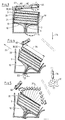
- FIGS. 3 to 5 In order to combat a target 76 approaching in the direction of arrow 75 corresponding to the target sector ignition pulses by a not shown Sensor technology on eight adjacent explosive chambers 42 to 49 given, these explosive chambers 42 to 49 the approaching Target 76 closest. This takes place according to FIGS. 3 to 5 first a tilt position of the assembly consisting of pressure plate 30, explosive housing 20 and base plate 13 towards the target drawn in accordance with arrow direction 75 and drawn to a reduced size 76. The end face 15 first bulges the bottom 4 until this one Opening 25 forms. The shaft 14 is now fixed and forms A pivot bearing 26 in the area of the opening 25.
- the explosive charge 21 is ignited, which is now is aimed at the target 76 so that this target 76 into one Curtain 77 flies in from the splinters 31 and is destroyed.
- This principle makes the function reproducible, almost error-free and maintenance-free, as well as small and inexpensive. It is suitable especially to combat attacking opponents with extreme short control time.
- the pressure plate 30 can also be made of a plastic or of a other material. The prerequisite is that the detonation effect of the explosives magazine 40 under one, for the ignition of the explosive charge 21 permanent threshold is damped.
- the explosive charge 21 can with a suitable, corresponding elastic Explosives consist of one piece.
- the disc shape according to Figure 3 is not necessary.
- the explosive charge 21 can also be used as a spiked or project-forming shaped charge be trained.
- the pressure plate 30 can also be convex or be concave.
Landscapes
- Engineering & Computer Science (AREA)
- Chemical & Material Sciences (AREA)
- Combustion & Propulsion (AREA)
- General Engineering & Computer Science (AREA)
- Aiming, Guidance, Guns With A Light Source, Armor, Camouflage, And Targets (AREA)
- Radar Systems Or Details Thereof (AREA)
Abstract
Description
- Figur 1
- einen Gefechtskopf im Schnitt
- Figur 2
- einen Ausschnitt des Gefechtskopfes nach Figur 1 gemäß der Schnittlinie II-II und
- Figuren 3-5
- Funktionsbilder des gezündeten Gefechtskopfes nach Figur 1.
Claims (11)
- Gefechtskopf bei dem die Sprengladung durch eine Stelleinrichtung auf das Ziel ausrichtbar ist,
dadurch gekennzeichnet,
daß in einem Gehäuse (3) bodenseitig ein etwa stempelförmiger, dickwandiger und schwenkbarer Abstandhalter (10) vorgesehen ist, dessen Schaft (14) mit einer Stirnseite (15) am Boden (4) des Gehäuses (3) anliegt und der Schaft (14) von einem freien Ringraum (17) umgeben ist, wobei eine im Gehäuse (3) geführte Kopfplatte (13) des Abstandshalters (10) die Sprengladung (21) bodenseitig abstützt, und daß eine Druckplatte (30) zwischen der Sprengladung (21) und einem zielseitigen, scheibenförmigen Sprengstoffmagazin (40) mit einzelnen Sprengstoffkammern (41 bis 56) liegt. - Gefechtskopf nach Anspruch 1,
dadurch gekennzeichnet,
daß das Sprengstoffmagazin (40) in Richtung auf die Druckplatte (30) rosettenförmig angeordnete, voneinander separierte Sprengstoffkammern (41 bis 56) aufweist, - Gefechtskopf nach Anspruch 1,
dadurch gekennzeichnet,
daß eine Spannvorrichtung (70) den Abstandhalter (10), die Sprengladung (21), die Druckplatte (30) und das Sprengstoffmagazin in dem Gehäuse (3) axial vorspannt. - Gefechtskopf nach Anspruch 1,
dadurch gekennzeichnet,
daß das Gehäuse (3) topfförmig und in Wirkrichtung (2) offen ausgebildet ist. - Gefechtskopf nach Anspruch 1,
dadurch gekennzeichnet,
daß die Sprengladung (21) vollständig in einem leichten, dünnen und leicht verformbaren Gehäuse (20) gekapselt ist und die Sprengladung (21) aus einem entsprechenden kunststoffgebundenen, elastischen Sprengstoff besteht. - Gefechtskopf nach Anspruch 1,
dadurch gekennzeichnet,
daß die Sprengladung (21) in zylindrischer Form vorliegt oder als Hohlladung oder als projektilbildende Ladung ausgebildet ist. - Gefechtskopf nach Anspruch 1,
dadurch gekennzeichnet,
daß die Druckplatte (30) als Blechgehäuse (32) mit innenliegenden Splittern (31) aus Schwermetall ausgebildet ist. - Gefechtskopf nach Anspruch 1,
dadurch gekennzeichnet,
daß die Sprengladung (21) in einzelnen Scheiben (19) vorliegt. - Gefechtskopf nach Ansprch 1,
dadurch gekennzeichnet,
daß die Druckplatte (30) eben, konvex oder konkav ausgebildet ist. - Gefechtskopf nach Anspruch 1,
dadurch gekennzeichnet,
daß die Sprengstoffkammern (41 bis 56) des Sprengstoffmagazins (40) einzeln oder in beliebiger Anzahl gleichzeitig oder nacheinander zündbar sind,
und die Sprengstoffkammern (41 bis 56) nur in Richtung auf die Druckplatte (30) nahezu unverdämmt sind. - Gefechtskopf nach Anspruch 1,
dadurch gekennzeichnet,
daß die Splitter (31) kubisch oder kugelförmig ausgebildet sind.
Priority Applications (3)
| Application Number | Priority Date | Filing Date | Title |
|---|---|---|---|
| DE4238482A DE4238482C2 (de) | 1992-11-14 | 1992-11-14 | Gefechtskopf |
| EP98114124A EP0977006B1 (de) | 1992-11-14 | 1998-07-29 | Gefechtskopf |
| DE59801693T DE59801693D1 (de) | 1998-07-29 | 1998-07-29 | Gefechtskopf |
Applications Claiming Priority (2)
| Application Number | Priority Date | Filing Date | Title |
|---|---|---|---|
| DE4238482A DE4238482C2 (de) | 1992-11-14 | 1992-11-14 | Gefechtskopf |
| EP98114124A EP0977006B1 (de) | 1992-11-14 | 1998-07-29 | Gefechtskopf |
Publications (2)
| Publication Number | Publication Date |
|---|---|
| EP0977006A1 true EP0977006A1 (de) | 2000-02-02 |
| EP0977006B1 EP0977006B1 (de) | 2001-10-10 |
Family
ID=25920448
Family Applications (1)
| Application Number | Title | Priority Date | Filing Date |
|---|---|---|---|
| EP98114124A Expired - Lifetime EP0977006B1 (de) | 1992-11-14 | 1998-07-29 | Gefechtskopf |
Country Status (2)
| Country | Link |
|---|---|
| EP (1) | EP0977006B1 (de) |
| DE (1) | DE4238482C2 (de) |
Cited By (2)
| Publication number | Priority date | Publication date | Assignee | Title |
|---|---|---|---|---|
| DE102019001597B3 (de) * | 2019-03-07 | 2020-07-30 | TDW Gesellschaft für verteidigungstechnische Wirksysteme mbH | Wirksystem für einen Flugkörper |
| CN117629001A (zh) * | 2024-01-25 | 2024-03-01 | 成都森田自动化设备有限公司 | 一种射孔弹自动称装药机 |
Families Citing this family (4)
| Publication number | Priority date | Publication date | Assignee | Title |
|---|---|---|---|---|
| US7930978B1 (en) | 2008-05-19 | 2011-04-26 | Raytheon Company | Forward firing fragmentation warhead |
| US8006623B2 (en) | 2008-11-17 | 2011-08-30 | Raytheon Company | Dual-mass forward and side firing fragmentation warhead |
| DE102013009789A1 (de) * | 2013-06-12 | 2014-12-18 | Diehl Bgt Defence Gmbh & Co. Kg | Gefechtskopf |
| FR3075946B1 (fr) * | 2017-12-22 | 2021-12-17 | Arianegroup Sas | Dispositif de generation d'eclats |
Citations (8)
| Publication number | Priority date | Publication date | Assignee | Title |
|---|---|---|---|---|
| GB574132A (en) * | 1942-06-12 | 1945-12-21 | Lewis Motley | Improvements in or relating to military land mines |
| US4034673A (en) | 1976-02-23 | 1977-07-12 | Calspan Corporation | Armor penetration shaped-charge projectile |
| DE3525147C1 (de) * | 1985-07-13 | 1987-01-15 | Diehl Gmbh & Co | Sturz-Flugkoerper zum Bekaempfen von insbesondere Radarstellungen |
| DE3605579C1 (en) * | 1986-02-21 | 1987-05-07 | Messerschmitt Boelkow Blohm | Missile for attacking targets underneath the flight path (trajectory) of the missile |
| DE3216142C1 (en) | 1982-04-30 | 1988-06-30 | Messerschmitt Boelkow Blohm | Fast-flying projectile with direction-forming charges |
| DE3820183A1 (de) * | 1988-06-14 | 1990-02-08 | Diehl Gmbh & Co | Flugkoerper mit einem schwenkbaren gefechtskopf |
| DE3515496A1 (de) * | 1985-04-30 | 1992-03-26 | Diehl Gmbh & Co | Hubschrauberabwehr-hohlladungsmine |
| GB2300465A (en) * | 1995-05-04 | 1996-11-06 | Rheinmetall Ind Gmbh | Missile with pivotal warhead |
Family Cites Families (1)
| Publication number | Priority date | Publication date | Assignee | Title |
|---|---|---|---|---|
| JP2554142B2 (ja) * | 1988-10-14 | 1996-11-13 | 三菱重工業株式会社 | 誘導飛しょう体 |
-
1992
- 1992-11-14 DE DE4238482A patent/DE4238482C2/de not_active Expired - Fee Related
-
1998
- 1998-07-29 EP EP98114124A patent/EP0977006B1/de not_active Expired - Lifetime
Patent Citations (8)
| Publication number | Priority date | Publication date | Assignee | Title |
|---|---|---|---|---|
| GB574132A (en) * | 1942-06-12 | 1945-12-21 | Lewis Motley | Improvements in or relating to military land mines |
| US4034673A (en) | 1976-02-23 | 1977-07-12 | Calspan Corporation | Armor penetration shaped-charge projectile |
| DE3216142C1 (en) | 1982-04-30 | 1988-06-30 | Messerschmitt Boelkow Blohm | Fast-flying projectile with direction-forming charges |
| DE3515496A1 (de) * | 1985-04-30 | 1992-03-26 | Diehl Gmbh & Co | Hubschrauberabwehr-hohlladungsmine |
| DE3525147C1 (de) * | 1985-07-13 | 1987-01-15 | Diehl Gmbh & Co | Sturz-Flugkoerper zum Bekaempfen von insbesondere Radarstellungen |
| DE3605579C1 (en) * | 1986-02-21 | 1987-05-07 | Messerschmitt Boelkow Blohm | Missile for attacking targets underneath the flight path (trajectory) of the missile |
| DE3820183A1 (de) * | 1988-06-14 | 1990-02-08 | Diehl Gmbh & Co | Flugkoerper mit einem schwenkbaren gefechtskopf |
| GB2300465A (en) * | 1995-05-04 | 1996-11-06 | Rheinmetall Ind Gmbh | Missile with pivotal warhead |
Cited By (3)
| Publication number | Priority date | Publication date | Assignee | Title |
|---|---|---|---|---|
| DE102019001597B3 (de) * | 2019-03-07 | 2020-07-30 | TDW Gesellschaft für verteidigungstechnische Wirksysteme mbH | Wirksystem für einen Flugkörper |
| CN117629001A (zh) * | 2024-01-25 | 2024-03-01 | 成都森田自动化设备有限公司 | 一种射孔弹自动称装药机 |
| CN117629001B (zh) * | 2024-01-25 | 2024-03-22 | 成都森田自动化设备有限公司 | 一种射孔弹自动称装药机 |
Also Published As
| Publication number | Publication date |
|---|---|
| DE4238482A1 (de) | 1999-03-11 |
| DE4238482C2 (de) | 2000-05-04 |
| EP0977006B1 (de) | 2001-10-10 |
Similar Documents
| Publication | Publication Date | Title |
|---|---|---|
| DE4426014B4 (de) | System zum Schutz eines Zieles gegen Flugkörper | |
| EP0314092B1 (de) | Sprenggeschoss mit einem Geschosskörper | |
| EP0583642B1 (de) | Gefechtskopf mit einer Tandemladung | |
| DE69605539T2 (de) | Zweifach wirkender explosionskopf und verfahren zum betreiben eines solchen gefechtskopfs | |
| EP0255130B1 (de) | Zünder für eine projektilbildende Ladung | |
| DE19524726B4 (de) | Gefechtskopf | |
| DE2809497A1 (de) | Abschussbehaelter fuer die dueppelung von lenkwaffen | |
| EP1292804B1 (de) | Selbstangetriebenes geschoss mit einem durchschlagskern | |
| DE19617221A1 (de) | Als Mörsergeschoß verbringbares Lenkprojektil | |
| DE3042063A1 (de) | Munitionssystem (werfergeschoss) und vorrichtung zum abfeuern desselben | |
| DE3515497A1 (de) | Panzerabwehr-mine | |
| DE2919807A1 (de) | Drallstabilisiertes treibspiegelgeschoss zur ueberwindung eines heterogenen widerstandes | |
| EP0977006B1 (de) | Gefechtskopf | |
| DE102007056785A1 (de) | Geschoss | |
| DE19917144B4 (de) | Kombinationswirksystem | |
| DE2835818C2 (de) | Sprengkörper mit projektilbildenden Belegungen | |
| DE2207840A1 (de) | Lagenunabhaengig wirkende streubare mine | |
| DE69810879T2 (de) | Projektil mit radialer Wirkrichtung | |
| DE3900442A1 (de) | Bomblet | |
| DE3515496C2 (de) | ||
| DE3933442C2 (de) | ||
| DE4011243C1 (de) | Gefechtskopf mit Splitterwirkung | |
| DE102012021671A1 (de) | Wirksysteme gegen SICBM- und RAM-Bedrohungen | |
| DE69618573T2 (de) | Geschoss mit gerichteter Splitterwirkung | |
| DE3934850C1 (de) | Gefechtskopf |
Legal Events
| Date | Code | Title | Description |
|---|---|---|---|
| PUAI | Public reference made under article 153(3) epc to a published international application that has entered the european phase |
Free format text: ORIGINAL CODE: 0009012 |
|
| 17P | Request for examination filed |
Effective date: 19990119 |
|
| AK | Designated contracting states |
Kind code of ref document: A1 Designated state(s): CH DE FR GB IT LI SE |
|
| AX | Request for extension of the european patent |
Free format text: AL;LT;LV;MK;RO;SI |
|
| 17Q | First examination report despatched |
Effective date: 20000314 |
|
| AKX | Designation fees paid |
Free format text: CH DE FR GB IT LI SE |
|
| GRAG | Despatch of communication of intention to grant |
Free format text: ORIGINAL CODE: EPIDOS AGRA |
|
| GRAG | Despatch of communication of intention to grant |
Free format text: ORIGINAL CODE: EPIDOS AGRA |
|
| GRAH | Despatch of communication of intention to grant a patent |
Free format text: ORIGINAL CODE: EPIDOS IGRA |
|
| GRAH | Despatch of communication of intention to grant a patent |
Free format text: ORIGINAL CODE: EPIDOS IGRA |
|
| GRAA | (expected) grant |
Free format text: ORIGINAL CODE: 0009210 |
|
| AK | Designated contracting states |
Kind code of ref document: B1 Designated state(s): CH DE FR GB IT LI SE |
|
| REG | Reference to a national code |
Ref country code: CH Ref legal event code: EP |
|
| REF | Corresponds to: |
Ref document number: 59801693 Country of ref document: DE Date of ref document: 20011115 |
|
| REG | Reference to a national code |
Ref country code: GB Ref legal event code: IF02 |
|
| REG | Reference to a national code |
Ref country code: CH Ref legal event code: NV Representative=s name: A. BRAUN, BRAUN, HERITIER, ESCHMANN AG PATENTANWAE |
|
| GBT | Gb: translation of ep patent filed (gb section 77(6)(a)/1977) |
Effective date: 20020114 |
|
| ET | Fr: translation filed | ||
| PLBE | No opposition filed within time limit |
Free format text: ORIGINAL CODE: 0009261 |
|
| STAA | Information on the status of an ep patent application or granted ep patent |
Free format text: STATUS: NO OPPOSITION FILED WITHIN TIME LIMIT |
|
| 26N | No opposition filed | ||
| PG25 | Lapsed in a contracting state [announced via postgrant information from national office to epo] |
Ref country code: DE Free format text: LAPSE BECAUSE OF NON-PAYMENT OF DUE FEES Effective date: 20030201 |
|
| PGFP | Annual fee paid to national office [announced via postgrant information from national office to epo] |
Ref country code: IT Payment date: 20060731 Year of fee payment: 9 |
|
| PGFP | Annual fee paid to national office [announced via postgrant information from national office to epo] |
Ref country code: SE Payment date: 20060727 Year of fee payment: 9 |
|
| EUG | Se: european patent has lapsed | ||
| PG25 | Lapsed in a contracting state [announced via postgrant information from national office to epo] |
Ref country code: SE Free format text: LAPSE BECAUSE OF NON-PAYMENT OF DUE FEES Effective date: 20070730 |
|
| REG | Reference to a national code |
Ref country code: CH Ref legal event code: PFA Owner name: DIEHL STIFTUNG & CO. Free format text: DIEHL STIFTUNG & CO.#STEPHANSTRASSE 49#90478 NUERNBERG (DE) -TRANSFER TO- DIEHL STIFTUNG & CO.#STEPHANSTRASSE 49#90478 NUERNBERG (DE) |
|
| PG25 | Lapsed in a contracting state [announced via postgrant information from national office to epo] |
Ref country code: IT Free format text: LAPSE BECAUSE OF NON-PAYMENT OF DUE FEES Effective date: 20070729 |
|
| PGFP | Annual fee paid to national office [announced via postgrant information from national office to epo] |
Ref country code: CH Payment date: 20100723 Year of fee payment: 13 |
|
| PGFP | Annual fee paid to national office [announced via postgrant information from national office to epo] |
Ref country code: GB Payment date: 20100624 Year of fee payment: 13 Ref country code: FR Payment date: 20100805 Year of fee payment: 13 |
|
| REG | Reference to a national code |
Ref country code: CH Ref legal event code: PL |
|
| GBPC | Gb: european patent ceased through non-payment of renewal fee |
Effective date: 20110729 |
|
| REG | Reference to a national code |
Ref country code: FR Ref legal event code: ST Effective date: 20120330 |
|
| PG25 | Lapsed in a contracting state [announced via postgrant information from national office to epo] |
Ref country code: FR Free format text: LAPSE BECAUSE OF NON-PAYMENT OF DUE FEES Effective date: 20110801 Ref country code: CH Free format text: LAPSE BECAUSE OF NON-PAYMENT OF DUE FEES Effective date: 20110731 Ref country code: LI Free format text: LAPSE BECAUSE OF NON-PAYMENT OF DUE FEES Effective date: 20110731 |
|
| PG25 | Lapsed in a contracting state [announced via postgrant information from national office to epo] |
Ref country code: GB Free format text: LAPSE BECAUSE OF NON-PAYMENT OF DUE FEES Effective date: 20110729 |