EP0977008A2 - Procédé et dispositif pour la détection de l' épaisseur d' une couche des dépôts - Google Patents
Procédé et dispositif pour la détection de l' épaisseur d' une couche des dépôts Download PDFInfo
- Publication number
- EP0977008A2 EP0977008A2 EP99810675A EP99810675A EP0977008A2 EP 0977008 A2 EP0977008 A2 EP 0977008A2 EP 99810675 A EP99810675 A EP 99810675A EP 99810675 A EP99810675 A EP 99810675A EP 0977008 A2 EP0977008 A2 EP 0977008A2
- Authority
- EP
- European Patent Office
- Prior art keywords
- temperature
- process medium
- thickness
- layer
- peltier element
- Prior art date
- Legal status (The legal status is an assumption and is not a legal conclusion. Google has not performed a legal analysis and makes no representation as to the accuracy of the status listed.)
- Granted
Links
Images


Classifications
-
- G—PHYSICS
- G01—MEASURING; TESTING
- G01B—MEASURING LENGTH, THICKNESS OR SIMILAR LINEAR DIMENSIONS; MEASURING ANGLES; MEASURING AREAS; MEASURING IRREGULARITIES OF SURFACES OR CONTOURS
- G01B21/00—Measuring arrangements or details thereof, where the measuring technique is not covered by the other groups of this subclass, unspecified or not relevant
- G01B21/02—Measuring arrangements or details thereof, where the measuring technique is not covered by the other groups of this subclass, unspecified or not relevant for measuring length, width, or thickness
- G01B21/08—Measuring arrangements or details thereof, where the measuring technique is not covered by the other groups of this subclass, unspecified or not relevant for measuring length, width, or thickness for measuring thickness
- G01B21/085—Measuring arrangements or details thereof, where the measuring technique is not covered by the other groups of this subclass, unspecified or not relevant for measuring length, width, or thickness for measuring thickness using thermal means
-
- G—PHYSICS
- G01—MEASURING; TESTING
- G01B—MEASURING LENGTH, THICKNESS OR SIMILAR LINEAR DIMENSIONS; MEASURING ANGLES; MEASURING AREAS; MEASURING IRREGULARITIES OF SURFACES OR CONTOURS
- G01B21/00—Measuring arrangements or details thereof, where the measuring technique is not covered by the other groups of this subclass, unspecified or not relevant
- G01B21/02—Measuring arrangements or details thereof, where the measuring technique is not covered by the other groups of this subclass, unspecified or not relevant for measuring length, width, or thickness
- G01B21/08—Measuring arrangements or details thereof, where the measuring technique is not covered by the other groups of this subclass, unspecified or not relevant for measuring length, width, or thickness for measuring thickness
Definitions
- the present invention relates to a method for determining the thickness of deposits on the inside of walls of containers and / or pipes, in which a process medium flows.
- the invention also includes a device to perform the above procedure.
- biofilms are particularly strong in the field of paper production pronounced because both the process temperatures are normally in one range are, which is ideal for the formation of cell cultures, and also because, on the other hand, in the process water a large amount of pulp and filler floats, which one offers the ideal breeding ground for these cultures. Also be based on ecological considerations, the process water flows in closed and ever smaller circuits, which further accelerates the formation of biofilms.
- the biofilm fragments detaching from the walls are for the tour of the paper making process but fatal because they usually to a demolition of the new paper webs and thus to production interruptions To give reason. This fact is countered by the fact that the process water Periodically so-called biocides are added, which are able to to kill cell cultures adhering to the walls and thus to break down the biofilm.
- a simple way to monitor the thickness of deposits in process water tanks is to branch off part of the process water in a line and to measure the heat conduction or the thermal resistance between the wall of the line and the process water through such a layer.
- Such a method is described, for example, in Chemical Processing, 4, 1990, pp. 34-38.
- a method for measuring the heat exchange efficiency of pipe systems is e.g. known from US 5,248,198. It becomes the thermal relaxation time there the conduit wall after a short heating of the same. Depending on the efficiency the heat exchange between the process water in the pipe and the Line of relaxation will be shorter or longer. So is with optimal Efficiency to expect a very short relaxation time while in the presence of a thick layer of deposits the heat flow is slowed down, and long relaxation times result.
- a major disadvantage of that described in US 5,248,198 The method is that they are designed for a test line as described there which is branched off from the actual process water circuit and that only a pulsed and no continuous measurement of the Layer thickness is possible.
- the biofilm to be measured may be necessary due to the large temperature deflection thermally destroyed and thereby the measurement be falsified.
- this object is achieved by that at the same time on at least two in contact with the process medium and areas exposed to the deposition process, heat conduction or the thermal resistance is measured between the surfaces and the process medium through the deposit layer is effective, and that for this measurement Means are present which have at least one of these surfaces at a temperature keep lower than the temperature of the process medium, and at least keep another of these surfaces at a temperature higher than the temperature of the process medium.
- the essence of the invention is therefore that through a positive and a negative temperature deflection relative to the process medium temperature Conditions are created that are as close as possible to those are, which prevail on the rest of the walls and yet have a high measuring accuracy allow.
- a first preferred embodiment of the invention is characterized in that that in addition to measuring the heat flows, the temperature of the process medium is measured to determine the thickness of the layer.
- Another preferred embodiment of the invention is characterized in that that the process medium is water and that the layer consists of a biofilm.
- Another preferred embodiment of the invention is characterized in that that the heat flows are measured in a measuring head, which is simply in the process water is immersed and its walls serve as measuring surfaces.
- Another embodiment of the invention has the feature that the temperature difference between the cold and the warm measuring surface is small, whereby one or a few 1 / 10th of a degree Celsius can already suffice.
- the temperature difference in particular should not be above 20 °, but preferably below 10 °, and especially should preferably be set below 5 ° Celsius, especially with biofilms an undisturbed measurement is possible. This e.g. at process medium temperatures of approx. 35 °.
- An additional embodiment of the invention has the feature that the thickness the parameters characterizing the layer are used for the addition to control funds in a regulated and optimal manner, which are able to to influence the thickness of the layer in a degrading or also in a constructive manner.
- the addition can be set such that the regulation to a predetermined layer thickness (setpoint).
- This object is achieved by a device in which at least at the same time two, in contact with the process medium and the deposition process exposed areas measured the heat conduction or the heat conduction resistance between the surfaces and the process medium through the deposit layer is effective, with means available for this measurement, which keep at least one of these surfaces at a temperature lower than that Temperature of the process medium, and at least one other of these surfaces keep at a temperature higher than the temperature of the process medium lies.
- the extent of the surfaces is preferred kept as low as possible in the flow direction of the process medium, so the dwell time of the process medium over the surfaces is as short as possible. Thereby a significant warming of the area sweeping over the areas becomes immediate Process water and an associated reduced heat flow largely prevented, and thus an additional source of error eliminated.
- Another preferred embodiment of the device according to the invention exists in that the cooling or heating of the measuring surfaces through the solder joints of a Peltier element is effected.
- FIG. 1 shows an embodiment of a measuring head 21 which is suitable for the Heat conduction or the heat conduction resistance between two surfaces 28, 29, which Form parts of the outer wall of the measuring head 21 and the process water 26 measure up.
- a section through an essentially cuboid measuring head is shown 21.
- the measuring head 21 is in this case via a fastening means 23 which is simultaneously passed measurement information 44, 54 in the process water flow 25 attached and therefore easily through a hatch or other opening in the Pipe system or a container.
- the measuring head 21 can by its Measuring head cap 20 have a streamlined outer shape.
- the shape of the measuring head 21 is preferably hydrodynamic, so the process water, the measuring surfaces 28, 29 of the measuring head 21 are as laminar as possible flows around.
- this brings The following two advantages: On the one hand, a removal of one Deposition such as a biofilm due to any flow vortices and thus preventing an undesirable reduction in the measurement signal.
- On the other hand can in the process water stream 25 floating, elongated solids (such as Cellulose lasers) pass the measuring head 21 in the laminar flow without collision, whereby an undesirable build-up of a layer of these solids and a associated signal corruption is avoided.
- This second effect will also favored by an optimal width of the sensor, which is larger than that Length of longest solid should be.
- the areas 28, 29 may possibly additionally provided with a suitable coating be so that the process water flow can be largely prevented 25 hindered the deposition process on the surfaces 28, 29, or deposits detaches from the measuring head.
- a suitable coating has, for example a layer of niobium-zirconium nitrite has been proven, which has a thickness of 1.5 - 3 ⁇ m is applied.
- the measuring head 21 is essentially made of a good thermal insulation Material, e.g. a plastic carrier block 24 made of PVDF plastic, in which other parts are embedded. Inside the support block 24 a Peltier element 11 is attached, which via a line 10 from a also in the support block 24 embedded central unit 22 with electrical current is fed.
- a Peltier element 11 is characterized in that it is a closed one Circle of at least two different lines connected in series different metals or alloys. Will the circuit of electrical The Peltier element has current flowing through it when the materials are selected appropriately the remarkable property that one of the solder joints 12 between the different lines cools while the other soldering point 13 heats up (so-called thermoelectric effect).
- the Peltier element 11 embedded in the measuring head 21 stands with its two solder points 12,13 in contact with contact blocks 14,15.
- These contact blocks 14, 15 are also embedded in the support block 24, are made of a thermally highly conductive Material, for example V4A steel (DIN 1.45.71), and form on it the Peltier element facing away from the surfaces exposed to the process water 26 28.29.
- the measuring head 21 or the blocks 14, 15 embedded therein can advantageously sealed with an O-ring construction so that the O-rings in addition to the sealing function also have a spring function. With this spring action of the O-rings are thermal linear expansion between the housing and Blocks 14, 15 balanced such that the contact forces on the Peltier module None exceed tolerance values. It is important that the contact blocks 14, 15 with one another are thermally decoupled.
- the thermal insulation between the two surfaces 28.29 or the contact blocks 14.15 should on the one hand be chosen so thick that good thermal insulation is guaranteed, and on the other hand thin enough be that the proportion of the areas 28, 29 with respect to the entire measuring head surface is as large as possible. This makes the sensitivity of the measuring head 21 overall is increased and possible non-linearities of the raw measurement signal are reduced. So can e.g. with a linearization of the raw signal a better resolution and thus high measurement accuracy can be achieved.
- the areas 28, 29 of the contact blocks 14.15 are the actual measuring surfaces and are exposed to the deposition process. It proves to be advantageous in the construction of the surfaces 28 and 29 to keep it small in its direction of flow 25.
- thermal sensors 16, 17 attached, which measure the temperatures prevailing in the contact blocks.
- the thermal sensors 16, 17 are connected to the central unit 22 via lines 18, 19.
- the principle of action of the measuring head 21 is now as follows: Becomes the Peltier element 11 flows through a current, the one solder joint 12 cools down. This Cooling in turn leads to a cooling of the with the solder joint 12 in thermal Contacting contact blocks 14. In particular, the heat flow leads from the contact block 14 to the solder joint 12 for cooling the process water 26 exposed area 28. If area 28 is free of deposits, this results in a very efficient heat flow from process water 26 to surface 28. As a result the large heat capacity of the process water 26 remains the temperature of the surface 28 near the temperature of the process water. Accordingly one becomes with the thermosensor 16 measure a temperature which is below, but in the vicinity the process water temperature is.
- the difference between the two temperatures measured with the thermal sensors 16 and 17 proves to be a suitable measure for determining the thickness of the deposit.
- the raw signal of the sensor nevertheless shows naturally a saturation behavior with increasing biofilm thickness. This non-linearity can be measured and used as the basis for a linearization algorithm become.
- the arithmetically corrected measurement signal is directly proportional to the biofilm thickness. In any case, there is a calibratable relationship between the difference the temperatures and the layers lying on the surfaces 28 and 29. This enables a simple evaluation of the measurement.
- An advantage of the arrangement proposed here is well, a large measurement signal and associated high measurement accuracy to achieve by the difference in the temperatures of the two surfaces 28 and 29 is used, even with small temperature deflections of surfaces 28 and 29 the process water temperature results in the difference in temperature of the areas 28 and 29 a large measured value. This is basically despite big Measured value has little influence on the growth of the biofilm.
- Another The advantage is given by the fact that a small one that occurs anyway thermal influence of the biofilm growth on the surfaces 28 and 29 in the first Approximation is compensated by the difference. The slightly higher temperature contribution the cooler side 28 with the slightly thicker biofilm is replaced by the slightly lower temperature contribution of the slightly thinner biofilm on the warmer Area 29 compensated.
- Another advantage of the method proposed here is based on the fact that a slight heating of the surface 29 leads to a thermal induced deposition of inorganic materials (such as lime) largely is avoided. These inorganic deposits would become undesirable Lead signal contribution that interferes with the measurement signal of the biofilm.
- the temperature difference between one of surfaces 28 and 29 and the temperature of the process water should be as small as possible should avoid falsification and not induce layer growth or to prevent the use of the difference in temperatures turns out as particularly advantageous. Even with small deviations in temperatures the areas 28 and 29 of the process water temperature already result a large, sensitive reading. In addition, there is the advantage that the use of a cold 28 and a warm 29 contact surface relative to the process water 26 may falsifications of the measured values that still occur induced or prevented layer growth compensated in a first approximation become.
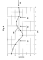
- the first method is based on measuring heat conduction. With her, the through the Peltier element 11 flowing electrical current kept constant and the difference the temperatures measured with the thermal sensors 16 and 17 can then can be used as a measure of the layer thickness. Is the difference in temperatures large, a large layer thickness is to be expected, since the heat or the cold cannot be discharged to the process water 26 via the surfaces 28 and 29. The smaller the difference, the better the heat exchange over the surfaces 28 and 29, and the thinner the deposit layer. The minimum of the temperature difference is to be expected with the deposit-free measuring probe 21. You watch a linear relationship over essential temperature and layer thickness ranges between the temperature difference and the layer thickness (cf. Figure 3b)).
- a parameterizable and calibratable connection can be made between the two sizes find what is particularly relevant for practice is.
- This first method is particularly simple and only requires that the Power supply of the Peltier element 11 is kept exactly constant. The difference is the temperature measured with the thermal sensors 16 and 17 in the simplest possible way.
- it can prove to be a disadvantage of this method that due to the change in temperatures on surfaces 28 and 29 increasing or decreasing deposition layer thickness also the deposition conditions on the surfaces change slightly, which is particularly relevant for biofilms can be.
- the second method is a little more elaborate, but is particularly necessary when needed Deposition characteristics that are as independent of the layer thickness as possible are an advantage. It is based that the difference between those measured with the thermal sensors 16 and 17 Temperatures is kept constant by the Peltier element 11 accordingly is controlled with electric current. With a deposit-free measuring probe 11 is thus closed with a maximum electric current through the Peltier element 11 count, since the heat generated by the Peltier element 11 under these conditions or cold as efficiently as possible through surfaces 28 and 29 to process water 26 can be delivered. If the deposit layer increases, so is the heat flow increasingly hindered by the surfaces 28 and 29, and by the temperature difference to keep constant at the thermal sensors 16 and 17, according to the electrical current through the Peltier element 11 can be reduced.
- the two aforementioned methods can also be used simultaneously if necessary, e.g. two measuring heads of the type of Fig. 1 (one at constant temperature and the other regulated to constant current) and their signals be evaluated together.
- Such an extension could add Information e.g. about the thermal sensitivity of the deposit layer, in particular a microbiological deposit layer.
- Two or more measuring heads could also be used so that the them assigned measuring surface pairs by a total heating and / or cooling with respect to their mean temperature value against each other and / or against each other the temperature of the process medium. For example, the average temperature of a first measuring head by cooling slightly below and one second measuring head by heating slightly above the temperature value of the process medium be moved. In this way, information in particular could be obtained the temperature dependence of the deposit layer.
- Two and more pairs of measuring surfaces could possibly also be in a common measuring head to get integrated.
- Figure 2 shows a structure as it is basically for the controlled addition of a Means can be used that is suitable, the layer thickness of a deposit to influence in a degrading or uplifting manner.
- the remedy involves a shift reduction effecting agent and in particular is a biocide.
- the measuring probe 21 depends on a simple attachment 39 in the process water flow 25, it is but also simply possible on their fastener 23 which is also the Line for the measurement signals represents through a hatch or a hole in a container to hang in the process water 26.
- the deposit layer here a biofilm 55 with a thickness of 56 is shown.
- control unit 30 Through an opening in the container wall 27 the measurement signals which characterize the layer thickness 56 are fed to a control unit 30, which in this case is outside of the container. It is also conceivable to control unit 30 as a whole in the Integrate measuring head 21 and embed it in the central unit 22.
- control unit 30 also has a tank 31 outside the container, which is used as a container for the biocide solution 32 used in the present example serves, and which with the process water tank via a pump 33 and Line communicates via an inlet 38.
- the biocide solution 32 is in the Able to degrade the biofilm when added to the process water 26.
- the control unit 30 has a signal line 34 to the biocide tank 31, by means of which characteristic data about the content of the biocide tank 31, e.g.
- the pump 33 can thus correspond to that of the measuring head 21 obtained data characterizing the deposit layer thickness 56 and if necessary, i.e. e.g. too thick a layer 56, a biocide stream 37 be added to the process water 26.
- a measuring head 21 can be used directly is advantageously preconditioned before the measurement, i.e. that at least that Surfaces 28, 29 or simply the entire measuring head 21 of a physical, undergo chemical and / or biological pretreatment.
- the growth of the biofilm on the areas 28, 29 from the beginning of the Use of sensors on motivated and once grown biofilm adheres well during the entire measurement phase (i.e. between two cleaning of the system).
- the biofilm situation in the water cycle of the system again at any time.
- immersing the measuring head 21 in is suitable medium similar to process medium 26 for a period of days to weeks.
- the otherwise sometimes observed delayed response the measuring heads, i.e. the time between the immersion of the Head into the medium until the initial formation of a biofilm with the associated evaluable measurement signal can be avoided.
- Figure 3a shows the operation of the measuring head 21 and the corresponding biocide addition control the control unit 30 using the first method, i.e. for constant electrical drive current of the Peltier element 11.
- the method is based essentially on the observed and schematically shown in Figure 3b) Calibratable functional relationship between the temperature difference 44 and the layer thickness 56.
- Figure 3b) shows one situation started in which there is no biofilm 55 and therefore the temperature difference 44 is small. The layer growth now leads to an increase with increasing time the temperature difference 44 due to the prevented heat exchange with the process water 26.
- Layer thickness 56 characteristic value 40 of the temperature difference 44 reacts the control unit 30 by adding the biocide 41 into the process water circuit starts.
- the layer thickness 56 then decreases and, of course, the temperature difference 44. falls below the temperature difference after a certain time again the critical value 40, the control unit 30 reacts by stopping the addition of biocide 42.
- the layer becomes the exceed critical value and the control unit 30 will in turn add biocide 32 43.
- the regulation of the addition of biocides will change after a short time level off on the layer growth and the layer thickness 56 will thus result stabilize the optimal biocide addition at the desired critical value.
- no leveling is necessary, but it takes place a continuous approximation of the value of the temperature difference from below to the critical value 40.
- FIG. 4 shows the regulation of the addition of biocide when using the second method, at which the temperature difference measured at the temperature sensors 16 and 17 44 is kept constant by the current flowing through the Peltier element 11 54 is adjusted.
- the graph starts at 0 in a situation without Biofilm 55.
- the layer thickness 56 then increases again, and the current 54 accordingly from until a predetermined, critical value of the current 50, which for a certain layer thickness 56 is characteristic, is undershot, and the control unit reacted with addition of biocide 51.
- FIG. 3 it swings to one the regulation of the addition of biocide to the layer growth, and the natural structure of the layer and biocide-induced degradation are roughly the same at a critical value of 50 the scale.
- control methods described above do not depend on the fact that the exact relationship between the layer thickness 56 and that of the measuring probe 21 determined measured value 44 or 54 is known.
- the measuring probe 21 and the control unit 30 are adapted to the environment in question anyway become. It may point out that the layer thickness 56 on the measuring probe 21 is not exactly identical to that on the critical process water tank walls 27. This does not detract from the procedure, however, because you simply use the critical value 40 or 50 for the measurands 44 or 54 empirically to the local ones Can adjust conditions.
- the dimensioning can be done vertically be chosen larger for the direction of flow. Because local warming or cooling of the process medium can occur when painting over the surfaces to prevent falsification of the measurement signal, make sure that the Process medium has a short residence time over the surface. Such Adulterations can also be taken into account and largely eliminated, by the flow rate of the process medium as a further measurement is taken into account.
Landscapes
- Physics & Mathematics (AREA)
- General Physics & Mathematics (AREA)
- Investigating Or Analyzing Materials Using Thermal Means (AREA)
- Length Measuring Devices With Unspecified Measuring Means (AREA)
- Analysing Materials By The Use Of Radiation (AREA)
- Measurement Of Length, Angles, Or The Like Using Electric Or Magnetic Means (AREA)
Applications Claiming Priority (2)
| Application Number | Priority Date | Filing Date | Title |
|---|---|---|---|
| CH159098 | 1998-07-28 | ||
| CH159098 | 1998-07-28 |
Publications (3)
| Publication Number | Publication Date |
|---|---|
| EP0977008A2 true EP0977008A2 (fr) | 2000-02-02 |
| EP0977008A3 EP0977008A3 (fr) | 2000-12-13 |
| EP0977008B1 EP0977008B1 (fr) | 2003-11-05 |
Family
ID=4213980
Family Applications (1)
| Application Number | Title | Priority Date | Filing Date |
|---|---|---|---|
| EP99810675A Expired - Lifetime EP0977008B1 (fr) | 1998-07-28 | 1999-07-27 | Procédé et dispositif pour la détection de l' épaisseur d' une couche des dépôts |
Country Status (3)
| Country | Link |
|---|---|
| EP (1) | EP0977008B1 (fr) |
| AT (1) | ATE253723T1 (fr) |
| DE (1) | DE59907599D1 (fr) |
Cited By (2)
| Publication number | Priority date | Publication date | Assignee | Title |
|---|---|---|---|---|
| WO2007068698A1 (fr) * | 2005-12-13 | 2007-06-21 | I.R.C.A. S.P.A. Industria Resistenze Corazzate E Affini | Dispositif de diagnostic pour un element de chauffage |
| DE102011080415A1 (de) * | 2011-08-04 | 2013-02-07 | Endress + Hauser Flowtec Ag | Verfahren zum Detektieren einer Belagsbildung oder einer Abrasion in einem Durchflussmessgerät |
Family Cites Families (3)
| Publication number | Priority date | Publication date | Assignee | Title |
|---|---|---|---|---|
| SU437882A1 (ru) * | 1971-07-22 | 1974-07-30 | Московский Ордена Трудового Красного Знамени Институт Нефтехимической И Газовой Промышленности Им.И.М. Губкина | Способ определени толщины сло гр зи парафиновых отложений в нефтепроводах |
| JPS59159008A (ja) * | 1983-03-01 | 1984-09-08 | Kawasaki Steel Corp | 高炉出銑樋耐火物の残厚推定方法 |
| US5360549A (en) * | 1993-04-27 | 1994-11-01 | Nalco Chemical Company | Feed back control deposit inhibitor dosage optimization system |
-
1999
- 1999-07-27 AT AT99810675T patent/ATE253723T1/de not_active IP Right Cessation
- 1999-07-27 EP EP99810675A patent/EP0977008B1/fr not_active Expired - Lifetime
- 1999-07-27 DE DE59907599T patent/DE59907599D1/de not_active Expired - Lifetime
Cited By (3)
| Publication number | Priority date | Publication date | Assignee | Title |
|---|---|---|---|---|
| WO2007068698A1 (fr) * | 2005-12-13 | 2007-06-21 | I.R.C.A. S.P.A. Industria Resistenze Corazzate E Affini | Dispositif de diagnostic pour un element de chauffage |
| DE102011080415A1 (de) * | 2011-08-04 | 2013-02-07 | Endress + Hauser Flowtec Ag | Verfahren zum Detektieren einer Belagsbildung oder einer Abrasion in einem Durchflussmessgerät |
| US9134165B2 (en) | 2011-08-04 | 2015-09-15 | Endress + Hauser Flowtec Ag | Method for detecting accretion or abrasion in a flow measuring device |
Also Published As
| Publication number | Publication date |
|---|---|
| ATE253723T1 (de) | 2003-11-15 |
| EP0977008A3 (fr) | 2000-12-13 |
| DE59907599D1 (de) | 2003-12-11 |
| EP0977008B1 (fr) | 2003-11-05 |
Similar Documents
| Publication | Publication Date | Title |
|---|---|---|
| DE2547832C2 (de) | Anordnung zum Messung des Grades der Verschmutzung in einer Rohrleitung, insbesondere in einem Wärmeaustauscher | |
| DE102014119223B3 (de) | Thermisches Durchflussmessgerät mit Diagnosefunktion | |
| DE102017120941B4 (de) | Thermisches Durchflussmessgerät und Verfahren zum Betreiben eines thermischen Durchflussmessgeräts | |
| DE112010000719T5 (de) | Verfahren und Vorrichtung zur Messung der Dicke von jeglicher Materialablagerung an einerInnenwand einer Struktur | |
| DE3222757C2 (fr) | ||
| EP2169392B1 (fr) | Procédé et dispositif destinés à la mesure de la dureté de l'eau | |
| EP2607892B1 (fr) | Procédé pour déterminer la conductivité thermique et la conductibilité thermique d'un échantillon de mesure | |
| DE4006689A1 (de) | Verfahren und vorrichtung zur erfassung der qualitaet von abwaessern | |
| EP4088077B1 (fr) | Procédé et dispositif de détermination de l'encrassement dans un échangeur de chaleur | |
| DE102007023823A1 (de) | Thermischer Massendurchflussmesser und Verfahren zu seinem Betrieb | |
| EP0180974B1 (fr) | Procédé et dispositif de mesure de vitesses de courant et/ou de débits | |
| EP0977008B1 (fr) | Procédé et dispositif pour la détection de l' épaisseur d' une couche des dépôts | |
| DE19623174C1 (de) | Vorrichtung zum Erfassen eines flüssigen oder gasförmigen Mediums | |
| WO2008142075A1 (fr) | Procédé de diagnostic pour appareils de mesure de débit massique thermiques | |
| DE2751925A1 (de) | Verfahren und vorrichtung zur kontrolle der korrodierenden, erodierenden und/oder inkrustierenden eigenschaften einer fluessigkeit | |
| DE69634604T2 (de) | Vorrichtung und verfahren zur detektion von mikrobiologischer verschmutzung in wässrigen systemen | |
| EP3234519A1 (fr) | Débitmètre thermique muni d'une fonction de diagnostic | |
| DE2810352C2 (de) | Einrichtung zur Überwachung der Korrosion | |
| DE3233329A1 (de) | Verfahren zum messen der stroemungsgeschwindigkeit eines fluids und einrichtung zur durchfuehrung des verfahrens | |
| DE4320395C2 (de) | Kondensatableiter für ein Fernwärmesystem | |
| EP1864109A1 (fr) | Procede pour determiner et pour controler la formation de depots dans un systeme d'eau | |
| WO2022207100A1 (fr) | Procédé et dispositif de détermination d'encrassement dans un échangeur de chaleur | |
| EP4058765B1 (fr) | Procédé de détermination d'une valeur réelle et/ou d'une plage de valeurs réelles d'au moins une variable d'état d'un fluide dans un écoulement de fluide au moyen d'au moins une particule indicatrice, procédé de exploitation d'un système de transport de fluide et système de détermination d'au moins une variable d'état | |
| DE102014111905B3 (de) | Rekonditionierung von beschichteten Sensoren | |
| DE29705673U1 (de) | Vorrichtung zur Messung und Einstellung des Alkoholgehalts im Feuchtmittel für den Offsetdruck |
Legal Events
| Date | Code | Title | Description |
|---|---|---|---|
| PUAI | Public reference made under article 153(3) epc to a published international application that has entered the european phase |
Free format text: ORIGINAL CODE: 0009012 |
|
| AK | Designated contracting states |
Kind code of ref document: A2 Designated state(s): AT BE CH CY DE DK ES FI FR GB GR IE IT LI LU MC NL PT SE |
|
| AX | Request for extension of the european patent |
Free format text: AL;LT;LV;MK;RO;SI |
|
| 17P | Request for examination filed |
Effective date: 20000619 |
|
| PUAL | Search report despatched |
Free format text: ORIGINAL CODE: 0009013 |
|
| AK | Designated contracting states |
Kind code of ref document: A3 Designated state(s): AT BE CH CY DE DK ES FI FR GB GR IE IT LI LU MC NL PT SE |
|
| AX | Request for extension of the european patent |
Free format text: AL;LT;LV;MK;RO;SI |
|
| AKX | Designation fees paid |
Free format text: AT BE CH CY DE DK ES FI FR GB GR IE IT LI LU MC NL PT SE |
|
| 17Q | First examination report despatched |
Effective date: 20030114 |
|
| GRAH | Despatch of communication of intention to grant a patent |
Free format text: ORIGINAL CODE: EPIDOS IGRA |
|
| GRAS | Grant fee paid |
Free format text: ORIGINAL CODE: EPIDOSNIGR3 |
|
| GRAA | (expected) grant |
Free format text: ORIGINAL CODE: 0009210 |
|
| AK | Designated contracting states |
Kind code of ref document: B1 Designated state(s): AT BE CH CY DE DK ES FI FR GB GR IE IT LI LU MC NL PT SE |
|
| PG25 | Lapsed in a contracting state [announced via postgrant information from national office to epo] |
Ref country code: NL Free format text: LAPSE BECAUSE OF FAILURE TO SUBMIT A TRANSLATION OF THE DESCRIPTION OR TO PAY THE FEE WITHIN THE PRESCRIBED TIME-LIMIT Effective date: 20031105 Ref country code: IT Free format text: LAPSE BECAUSE OF FAILURE TO SUBMIT A TRANSLATION OF THE DESCRIPTION OR TO PAY THE FEE WITHIN THE PRE;WARNING: LAPSES OF ITALIAN PATENTS WITH EFFECTIVE DATE BEFORE 2007 MAY HAVE OCCURRED AT ANY TIME BEFORE 2007. THE CORRECT EFFECTIVE DATE MAY BE DIFFERENT FROM THE ONE RECORDED.SCRIBED TIME-LIMIT Effective date: 20031105 Ref country code: IE Free format text: LAPSE BECAUSE OF FAILURE TO SUBMIT A TRANSLATION OF THE DESCRIPTION OR TO PAY THE FEE WITHIN THE PRESCRIBED TIME-LIMIT Effective date: 20031105 Ref country code: GB Free format text: LAPSE BECAUSE OF FAILURE TO SUBMIT A TRANSLATION OF THE DESCRIPTION OR TO PAY THE FEE WITHIN THE PRESCRIBED TIME-LIMIT Effective date: 20031105 Ref country code: CY Free format text: LAPSE BECAUSE OF FAILURE TO SUBMIT A TRANSLATION OF THE DESCRIPTION OR TO PAY THE FEE WITHIN THE PRESCRIBED TIME-LIMIT Effective date: 20031105 |
|
| REG | Reference to a national code |
Ref country code: GB Ref legal event code: FG4D Free format text: NOT ENGLISH |
|
| REG | Reference to a national code |
Ref country code: CH Ref legal event code: EP |
|
| REF | Corresponds to: |
Ref document number: 59907599 Country of ref document: DE Date of ref document: 20031211 Kind code of ref document: P |
|
| REG | Reference to a national code |
Ref country code: CH Ref legal event code: NV Representative=s name: ING. MARCO ZARDI C/O M. ZARDI & CO. S.A. |
|
| REG | Reference to a national code |
Ref country code: IE Ref legal event code: FG4D Free format text: GERMAN |
|
| PG25 | Lapsed in a contracting state [announced via postgrant information from national office to epo] |
Ref country code: SE Free format text: LAPSE BECAUSE OF FAILURE TO SUBMIT A TRANSLATION OF THE DESCRIPTION OR TO PAY THE FEE WITHIN THE PRESCRIBED TIME-LIMIT Effective date: 20040205 Ref country code: GR Free format text: LAPSE BECAUSE OF FAILURE TO SUBMIT A TRANSLATION OF THE DESCRIPTION OR TO PAY THE FEE WITHIN THE PRESCRIBED TIME-LIMIT Effective date: 20040205 Ref country code: DK Free format text: LAPSE BECAUSE OF FAILURE TO SUBMIT A TRANSLATION OF THE DESCRIPTION OR TO PAY THE FEE WITHIN THE PRESCRIBED TIME-LIMIT Effective date: 20040205 |
|
| PG25 | Lapsed in a contracting state [announced via postgrant information from national office to epo] |
Ref country code: ES Free format text: LAPSE BECAUSE OF FAILURE TO SUBMIT A TRANSLATION OF THE DESCRIPTION OR TO PAY THE FEE WITHIN THE PRESCRIBED TIME-LIMIT Effective date: 20040216 |
|
| NLV1 | Nl: lapsed or annulled due to failure to fulfill the requirements of art. 29p and 29m of the patents act | ||
| GBV | Gb: ep patent (uk) treated as always having been void in accordance with gb section 77(7)/1977 [no translation filed] |
Effective date: 20031105 |
|
| ET | Fr: translation filed | ||
| REG | Reference to a national code |
Ref country code: IE Ref legal event code: FD4D |
|
| PG25 | Lapsed in a contracting state [announced via postgrant information from national office to epo] |
Ref country code: LU Free format text: LAPSE BECAUSE OF NON-PAYMENT OF DUE FEES Effective date: 20040727 Ref country code: AT Free format text: LAPSE BECAUSE OF NON-PAYMENT OF DUE FEES Effective date: 20040727 |
|
| PG25 | Lapsed in a contracting state [announced via postgrant information from national office to epo] |
Ref country code: MC Free format text: LAPSE BECAUSE OF NON-PAYMENT OF DUE FEES Effective date: 20040731 Ref country code: BE Free format text: LAPSE BECAUSE OF NON-PAYMENT OF DUE FEES Effective date: 20040731 |
|
| PLBE | No opposition filed within time limit |
Free format text: ORIGINAL CODE: 0009261 |
|
| STAA | Information on the status of an ep patent application or granted ep patent |
Free format text: STATUS: NO OPPOSITION FILED WITHIN TIME LIMIT |
|
| 26N | No opposition filed |
Effective date: 20040806 |
|
| BERE | Be: lapsed |
Owner name: W. *KOLB A.G. Effective date: 20040731 |
|
| REG | Reference to a national code |
Ref country code: CH Ref legal event code: PCAR Free format text: ISLER & PEDRAZZINI AG;POSTFACH 1772;8027 ZUERICH (CH) |
|
| BERE | Be: lapsed |
Owner name: W. *KOLB A.G. Effective date: 20040731 |
|
| PG25 | Lapsed in a contracting state [announced via postgrant information from national office to epo] |
Ref country code: PT Free format text: LAPSE BECAUSE OF NON-PAYMENT OF DUE FEES Effective date: 20040405 |
|
| REG | Reference to a national code |
Ref country code: FR Ref legal event code: PLFP Year of fee payment: 17 |
|
| REG | Reference to a national code |
Ref country code: FR Ref legal event code: PLFP Year of fee payment: 18 |
|
| PGFP | Annual fee paid to national office [announced via postgrant information from national office to epo] |
Ref country code: DE Payment date: 20160722 Year of fee payment: 18 Ref country code: FI Payment date: 20160713 Year of fee payment: 18 Ref country code: CH Payment date: 20160712 Year of fee payment: 18 |
|
| PGFP | Annual fee paid to national office [announced via postgrant information from national office to epo] |
Ref country code: FR Payment date: 20160721 Year of fee payment: 18 |
|
| REG | Reference to a national code |
Ref country code: DE Ref legal event code: R119 Ref document number: 59907599 Country of ref document: DE |
|
| REG | Reference to a national code |
Ref country code: CH Ref legal event code: PL |
|
| REG | Reference to a national code |
Ref country code: FR Ref legal event code: ST Effective date: 20180330 |
|
| PG25 | Lapsed in a contracting state [announced via postgrant information from national office to epo] |
Ref country code: CH Free format text: LAPSE BECAUSE OF NON-PAYMENT OF DUE FEES Effective date: 20170731 Ref country code: DE Free format text: LAPSE BECAUSE OF NON-PAYMENT OF DUE FEES Effective date: 20180201 Ref country code: FI Free format text: LAPSE BECAUSE OF NON-PAYMENT OF DUE FEES Effective date: 20170727 Ref country code: LI Free format text: LAPSE BECAUSE OF NON-PAYMENT OF DUE FEES Effective date: 20170731 |
|
| PG25 | Lapsed in a contracting state [announced via postgrant information from national office to epo] |
Ref country code: FR Free format text: LAPSE BECAUSE OF NON-PAYMENT OF DUE FEES Effective date: 20170731 |