EP0977021B1 - Méthode pour la mesure du débit d'un fluide dans un canal d'écoulement - Google Patents
Méthode pour la mesure du débit d'un fluide dans un canal d'écoulement Download PDFInfo
- Publication number
- EP0977021B1 EP0977021B1 EP99115842A EP99115842A EP0977021B1 EP 0977021 B1 EP0977021 B1 EP 0977021B1 EP 99115842 A EP99115842 A EP 99115842A EP 99115842 A EP99115842 A EP 99115842A EP 0977021 B1 EP0977021 B1 EP 0977021B1
- Authority
- EP
- European Patent Office
- Prior art keywords
- pressure
- pressure difference
- volume flow
- measuring
- measured
- Prior art date
- Legal status (The legal status is an assumption and is not a legal conclusion. Google has not performed a legal analysis and makes no representation as to the accuracy of the status listed.)
- Expired - Lifetime
Links
- 238000000034 method Methods 0.000 title claims abstract description 13
- 239000012530 fluid Substances 0.000 title 1
- 238000005259 measurement Methods 0.000 claims abstract description 15
- 230000003068 static effect Effects 0.000 claims abstract description 15
- 238000009530 blood pressure measurement Methods 0.000 claims description 2
- 238000001514 detection method Methods 0.000 claims description 2
- 238000010079 rubber tapping Methods 0.000 description 16
- 239000003570 air Substances 0.000 description 10
- 238000012544 monitoring process Methods 0.000 description 9
- 239000007789 gas Substances 0.000 description 5
- 230000032683 aging Effects 0.000 description 3
- 238000011109 contamination Methods 0.000 description 3
- 238000012937 correction Methods 0.000 description 3
- 239000012080 ambient air Substances 0.000 description 2
- 230000006835 compression Effects 0.000 description 2
- 238000007906 compression Methods 0.000 description 2
- 238000010438 heat treatment Methods 0.000 description 2
- VNWKTOKETHGBQD-UHFFFAOYSA-N methane Chemical compound C VNWKTOKETHGBQD-UHFFFAOYSA-N 0.000 description 2
- 238000004140 cleaning Methods 0.000 description 1
- 238000010276 construction Methods 0.000 description 1
- 238000013461 design Methods 0.000 description 1
- 238000011161 development Methods 0.000 description 1
- 230000018109 developmental process Effects 0.000 description 1
- 238000010586 diagram Methods 0.000 description 1
- 238000000502 dialysis Methods 0.000 description 1
- 239000000385 dialysis solution Substances 0.000 description 1
- 239000003517 fume Substances 0.000 description 1
- 230000001771 impaired effect Effects 0.000 description 1
- 230000007774 longterm Effects 0.000 description 1
- 238000004519 manufacturing process Methods 0.000 description 1
- 239000012528 membrane Substances 0.000 description 1
- 239000003345 natural gas Substances 0.000 description 1
- 238000012549 training Methods 0.000 description 1
Images


Classifications
-
- G—PHYSICS
- G01—MEASURING; TESTING
- G01F—MEASURING VOLUME, VOLUME FLOW, MASS FLOW OR LIQUID LEVEL; METERING BY VOLUME
- G01F1/00—Measuring the volume flow or mass flow of fluid or fluent solid material wherein the fluid passes through a meter in a continuous flow
- G01F1/05—Measuring the volume flow or mass flow of fluid or fluent solid material wherein the fluid passes through a meter in a continuous flow by using mechanical effects
- G01F1/34—Measuring the volume flow or mass flow of fluid or fluent solid material wherein the fluid passes through a meter in a continuous flow by using mechanical effects by measuring pressure or differential pressure
- G01F1/36—Measuring the volume flow or mass flow of fluid or fluent solid material wherein the fluid passes through a meter in a continuous flow by using mechanical effects by measuring pressure or differential pressure the pressure or differential pressure being created by the use of flow constriction
- G01F1/363—Measuring the volume flow or mass flow of fluid or fluent solid material wherein the fluid passes through a meter in a continuous flow by using mechanical effects by measuring pressure or differential pressure the pressure or differential pressure being created by the use of flow constriction with electrical or electro-mechanical indication
-
- G—PHYSICS
- G01—MEASURING; TESTING
- G01F—MEASURING VOLUME, VOLUME FLOW, MASS FLOW OR LIQUID LEVEL; METERING BY VOLUME
- G01F25/00—Testing or calibration of apparatus for measuring volume, volume flow or liquid level or for metering by volume
- G01F25/10—Testing or calibration of apparatus for measuring volume, volume flow or liquid level or for metering by volume of flowmeters
- G01F25/13—Testing or calibration of apparatus for measuring volume, volume flow or liquid level or for metering by volume of flowmeters using a reference counter
-
- G—PHYSICS
- G01—MEASURING; TESTING
- G01F—MEASURING VOLUME, VOLUME FLOW, MASS FLOW OR LIQUID LEVEL; METERING BY VOLUME
- G01F25/00—Testing or calibration of apparatus for measuring volume, volume flow or liquid level or for metering by volume
- G01F25/10—Testing or calibration of apparatus for measuring volume, volume flow or liquid level or for metering by volume of flowmeters
- G01F25/15—Testing or calibration of apparatus for measuring volume, volume flow or liquid level or for metering by volume of flowmeters specially adapted for gas meters
-
- G—PHYSICS
- G01—MEASURING; TESTING
- G01L—MEASURING FORCE, STRESS, TORQUE, WORK, MECHANICAL POWER, MECHANICAL EFFICIENCY, OR FLUID PRESSURE
- G01L19/00—Details of, or accessories for, apparatus for measuring steady or quasi-steady pressure of a fluent medium insofar as such details or accessories are not special to particular types of pressure gauges
- G01L19/0007—Fluidic connecting means
- G01L19/0015—Fluidic connecting means using switching means
Definitions
- the invention relates to a method for determining the Gas volume flow in a flow channel by measuring the differential pressure over at least one arranged in the flow channel Orifice plate.
- the measurement of the differential pressure of a gas flow over a choke point and in particular the combined measurement of Differential pressure differences arranged one behind the other in the flow channel Throttling points allows the gas volume flow to be determined, which is particularly the case with exhaust air systems such as Deductions to determine and regulate the air flow from Meaning is.
- the sources of error described above also exist for Sensors whose work is based on thermal heating, since the thermal heating also causes signs of aging can come that change the sensor output signal.
- the surfaces can also become dirty with thermal sensors or corrode, which also leads to the corresponding Leads to mistakes.
- From US-A-3 701 280 is a method for measuring a Natural gas flow known in which a super compression correction factor is formed by the measured static pressure with selected functions of pressure, temperature and specific weight multiplied and a selected constant Value is added to this product.
- the super compression correction factor is measured with the from the measured static Pressure formed absolute pressure to an overall correction factor multiplied, which is used to measure the gas flow correct and thereby automatically the supercompressibility over selected ranges of pressure, temperature and specific weight.
- the object underlying the invention is therefore in developing the method of the type mentioned at the beginning, that an error detection is possible.
- the inputs of the pressure difference sensor switched self-monitoring can be carried out, with monitoring based on a self-created control characteristic and errors are reported.
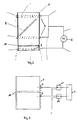
- 1A to 1C is a device schematically for measuring the differential pressure of a gas flow in one Flow channel 1 and shown above a throttle, between the pressure tapping points 3 and 4 in Flow channel 1 is provided, however, not in more detail in FIG. 1A to 1C is shown.
- it can be a device for measuring the differential pressure of a Exhaust air flow of an exhaust system, for example a fume cupboard act.
- the pressure points 3 and 4 which are in the form of bores are available with the inputs of a pressure difference sensor 2 connected.
- 1A is the normal one with the switch position S1 Operating state shown. Is in this operating state the differential pressure sensor 2 with the pressure tapping points 3 and 4 i.e. with the negative pressure tapping point 4 and the positive Pressure tapping point 3 connected so that about the measurement the pressure difference determines the volume flow can be.
- FIG. 1B shows the switching state S2 for the zero point adjustment.
- this switching state S2 the inputs of the Pressure difference sensor 2 connected to a short-circuit line 6, the pressure points 7 and 8 in front of and behind the Throttle point short-circuits.
- switch position S2 is therefore at both inputs of the pressure difference sensor 2 the same pressure, so that theoretically the zero point is measured should be. Results from aging of the sensor, contamination or other error factors a non-zero Measured value in the case of a sensor short circuit, it can be Error value can be determined.
- the device If the device is part of a controller, it can carry out an internal offset and that deviating from zero in the case of a sensor short circuit Subtract the measured value from the actual measured value so that a corresponding one Software carry out a zero adjustment can. It has been shown that such automatic zero point adjustment the accuracy of the determination greatly increased in particular by low volume flows can be.
- FIG. 1C shows a further switching state S3, in which the inputs of the pressure difference sensor 2 with the positive Pressure tapping point 3 and a line leading to the environment 5 are connected.
- this switch position is the Sensor 2 reversed, its negative input is on the positive Pressure tapping point and its positive input is on the ambient pressure.
- the sensor 2 can in this switch position S3 measure the static pressure loss of the measuring point.
- Fig. 2 shows schematically an embodiment of a Arrangement for determining the air volume flow in a flow channel 1.
- a throttle point 10 is in the form of an aperture arranged in the flow channel 1 and at the inputs of a Pressure difference sensor 2 are the effective pressures of pressure tapping points 3 and 4 in front of and behind the throttle point 10.
- the pressure decrease point 4 consists of two parts namely one place before and one place after another Throttle point in the form of a throttle valve 9.
- the orifice 10 is for example a differential pressure orifice and Pressure tapping points 3, 4 consist of bores with Ring channels are interconnected, leading to the pressure difference sensor 2 lead.
- the above measuring device can be part of a Control arrangement for controlling the volume flow in the flow channel 1 be that at the start of operation with a new pressure sensor and unpolluted piping works.
- This Control arrangement is located on an air consumer, for example, especially a deduction.
- the static pressure loss of such a consumer is not known and also not necessary for operation, since the Differential pressure sensor 2 is new and not dirty.
- the volume flow at the control point is then identical to the volume flow at the measuring point. If a first differential pressure difference ⁇ P 1 is then measured at the pressure tapping point 3, a first pair of values can be written into a table.
- a table for the control measuring point can be determined by opening the throttle valve 9 step by step up to 90 °. In this way, the control arrangement creates its own control characteristic depending on the associated consumer.
- Measurements have shown that measured values at the control measuring point and at the normal measuring point by a maximum of 10% from each other may deviate, deviations of more than 10% are to be regarded as errors.
- the pressure tapping point 3 and 4 the volume flow measured. Periodically is by maintaining the position of the throttle valve 9 of the switching position S1 switched to the switching position S3 and the new differential pressure difference ⁇ P at the control point measured.
- the volume flow of the control point be determined. Is there a measurement difference of more than 10% between the volume flow at the control point and at the Measuring point, the measurement of the system is faulty to watch. The system can detect this error and one Trigger alarm signal. The person working on the consumer can then check the system, for example cleaning the measuring device.
- Fig. 3 shows a further embodiment of a Device for measuring the differential pressure in a flow channel 1, in which only a single throttle body in the form a measuring aperture 10 is provided. Instead of the differential pressure measuring orifice 10, a Venturi nozzle can also be provided. in the The differential pressure sensor 2 with the two is normal operation Pressure tapping points 3, 4 in front of and behind the orifice 10 connected. With the help of solenoid valves 11 a zero adjustment can be made done by the inputs of the pressure difference sensor 2 accordingly switched to switch position S2 become.
- the monitoring takes place in that the switching position of the Differential pressure sensor 2 from normal operation in the switch position S1 to the adjustment mode in switch position S2 is switched in at both inputs of the pressure difference sensor 2 is the same pressure.
- the switch position S3 i.e. a control point becomes in the system monitoring operation measured against the ambient pressure.
- FIG. 4 shows an embodiment that with 2/3-way valves 11 works.
- the left 3-way valve is 11 to the positive input of the pressure difference sensor as well as the ambient air line and to the positive pressure tapping point connected.
- the right 3-way valve is on the negative Input of the pressure difference sensor 2 and at the negative Pressure point.
- the solenoid valves are in the rest position 11 set so that the positive and negative Pressure tapping point with the inputs of the pressure difference sensor 2 are connected. If in the middle in Fig. 4 Switch position shown the right solenoid valve 11th is switched, then the same is at both sensor inputs Pressure signal, so that the sensor 2 deliver a zero signal should.
- FIG. 5 shows a corresponding exemplary embodiment, where with the help of 2/2-way solenoid valves 11 a switchover he follows.
- the left normal switch position is the positive pressure tapping point at the positive input of the pressure difference sensor 2 and is the negative pressure point at the negative input of the pressure difference sensor 2. That is the normal case in which a measurement is made.
- Both solenoid valves 11 are opened. Then lies the same at both inputs of the pressure difference sensor 2 Pressure so that a zero adjustment can take place.
- This switch position is shown in the middle of Fig. 5.
- the left solenoid valve becomes a system monitor again closed, as in Fig. 5 in the right switch position is shown. Then it is at the negative input of the pressure difference sensor 2 a positive print while the right one Solenoid valve is switched to passage, so that there sets the lower ambient pressure. The arrangement is switched to system monitoring.
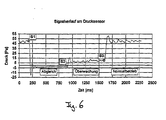
- FIG. 6 shows the course of the output signal at the pressure sensor 2 versus time in different modes of adjustment, monitoring and in normal operation.
- the pressure difference sensor 2 is initially up to point S1 switched to normal operation. It is an example Pressure of 45 Pa. Then the adjustment mode switched so that after a short settling phase the pressure is reduced to -2 Pa. Then it happens an independent zero point adjustment by the value of -2 Pa is set to zero.
- point S2 is on system monitoring changed so that the pressure rises to +7 Pa. This allows the old measuring point to be checked at point S1 become. After a certain time, the system switches again to normal operation. In this way is one complete system monitoring with zero point adjustment been. Is such a comparison not possible or the values differ in monitoring mode and in Normal operation more than +/- 10% of the previously recorded comparison value, a service alarm can be issued.
Landscapes
- Physics & Mathematics (AREA)
- General Physics & Mathematics (AREA)
- Fluid Mechanics (AREA)
- Measuring Volume Flow (AREA)
- Measuring Fluid Pressure (AREA)
- Flow Control (AREA)
Claims (5)
- Procédé de détermination du débit volumique de gaz dans un conduit d'écoulement par mesure de la différence de pression effective au moyen d'au moins un orifice de mesure disposé dans le conduit d'écoulement, caractérisé en ce quependant la mesure de la différence de pression effective, la pression statique en un emplacement de mesure de contrôle, à l'endroit duquel se présente le même débit volumique qu'à l'endroit de l'orifice de mesure, est mesurée à certains intervalles et, à partir de là, le débit volumique est déterminé au moyen d'une courbe caractéristique, recueillie au préalable, de la pression statique en fonction du débit volumique au même emplacement,puis, une indication d'erreur se présente lorsque le débit volumique obtenu d'après la courbe caractéristique à partir de la pression statique mesurée s'écarte, dans une mesure préfixée, du débit volumique obtenu à partir de la différence de pression mesurée à l'endroit de l'orifice de mesure.
- Procédé suivant la revendication 1, caractérisé en ce qu'avant la mesure de la différence de pression effective, une compensation à zéro est effectuée d'une manière telle qu'est mesurée la différence de pression en deux emplacements dans le conduit d'écoulement à l'endroit desquels la même pression règne effectivement et que, lors de la mesure d'une différence de pression différant de zéro, une compensation à zéro correspondante est effectuée.
- Procédé suivant la revendication 1 ou 2, caractérisé en ce qu'un orifice de mesure fixe et un orifice de mesure variable sont disposés dans le conduit d'écoulement et, lors de la mesure de la différence de pression effective, l'une des deux valeurs de mesure à partir desquelles la différence de pression effective est formée est formée à partir de la pression sur l'orifice de mesure variable.
- Procédé suivant la revendication 1, 2 ou 3, caractérisé en ce que la compensation à zéro et la détermination d'erreur s'effectuent automatiquement.
- Procédé suivant la revendication 1, caractérisé en ce qu'il est procédé à une commutation à intervalles réguliers entre la mesure de pression différentielle et la mesure de la pression statique.
Applications Claiming Priority (3)
| Application Number | Priority Date | Filing Date | Title |
|---|---|---|---|
| DE19600291 | 1996-01-05 | ||
| DE19600291A DE19600291C2 (de) | 1996-01-05 | 1996-01-05 | Verfahren zum Bestimmen des Gasvolumenstromes in einem Strömungskanal durch Messung der Wirkdruckdifferenz |
| EP96120811A EP0783098A1 (fr) | 1996-01-05 | 1996-12-23 | Dispositif de mesure de la pression différentielle effective d'un courant de gaz |
Related Parent Applications (1)
| Application Number | Title | Priority Date | Filing Date |
|---|---|---|---|
| EP96120811A Division EP0783098A1 (fr) | 1996-01-05 | 1996-12-23 | Dispositif de mesure de la pression différentielle effective d'un courant de gaz |
Publications (2)
| Publication Number | Publication Date |
|---|---|
| EP0977021A1 EP0977021A1 (fr) | 2000-02-02 |
| EP0977021B1 true EP0977021B1 (fr) | 2001-12-05 |
Family
ID=7782231
Family Applications (2)
| Application Number | Title | Priority Date | Filing Date |
|---|---|---|---|
| EP96120811A Withdrawn EP0783098A1 (fr) | 1996-01-05 | 1996-12-23 | Dispositif de mesure de la pression différentielle effective d'un courant de gaz |
| EP99115842A Expired - Lifetime EP0977021B1 (fr) | 1996-01-05 | 1996-12-23 | Méthode pour la mesure du débit d'un fluide dans un canal d'écoulement |
Family Applications Before (1)
| Application Number | Title | Priority Date | Filing Date |
|---|---|---|---|
| EP96120811A Withdrawn EP0783098A1 (fr) | 1996-01-05 | 1996-12-23 | Dispositif de mesure de la pression différentielle effective d'un courant de gaz |
Country Status (3)
| Country | Link |
|---|---|
| EP (2) | EP0783098A1 (fr) |
| AT (1) | ATE210281T1 (fr) |
| DE (2) | DE19600291C2 (fr) |
Families Citing this family (7)
| Publication number | Priority date | Publication date | Assignee | Title |
|---|---|---|---|---|
| DE19940042B4 (de) * | 1999-08-24 | 2004-03-25 | Waldner Laboreinrichtungen Gmbh & Co | Vorrichtung zum Regeln des Luftvolumenstroms für einen Abzug |
| GB2368398A (en) * | 2000-09-27 | 2002-05-01 | Blease Medical Equipment Ltd | Apparatus and method for measuring fluid flow |
| JP2004525330A (ja) * | 2001-02-05 | 2004-08-19 | バルドナー ラボラインリヒトゥンゲン ゲーエムベーハー ウント ツェーオー.カーゲー | 実験室局所排気装置用の排気体積流量調節装置 |
| DE102006058269B4 (de) * | 2006-12-08 | 2010-09-02 | Endress & Hauser Meßtechnik GmbH & Co. KG | Verfahren zur Kalibrierung mindestens eines Drucksensors und entsprechender Drucksensor |
| CN102003983A (zh) * | 2010-12-09 | 2011-04-06 | 沈阳北星仪表制造有限公司 | 智能差压平衡流量计 |
| DE102013114495A1 (de) * | 2013-12-19 | 2015-06-25 | S.K.I. GmbH | Verfahren sowie Messanordnung nach dem Differenzdruckprinzip mit Nullpunktabgleich |
| CN116202677B (zh) * | 2023-02-08 | 2025-11-21 | 中国航发沈阳发动机研究所 | 一种气压测量仪参考端压力稳定装置 |
Family Cites Families (6)
| Publication number | Priority date | Publication date | Assignee | Title |
|---|---|---|---|---|
| US3596680A (en) * | 1969-02-24 | 1971-08-03 | Donald L Adams | Plug valve manifold |
| US3701280A (en) * | 1970-03-18 | 1972-10-31 | Daniel Ind Inc | Method and apparatus for determining the supercompressibility factor of natural gas |
| US4453417A (en) * | 1982-03-08 | 1984-06-12 | Anderson, Greenwood & Company | Unitized measurement instrument connector apparatus |
| US4879912A (en) * | 1988-03-08 | 1989-11-14 | J. M. Huber Corporation | Unitized instrument manifold |
| SE513524C2 (sv) * | 1994-02-18 | 2000-09-25 | Gambro Med Tech Ab | System jämte förfarande för beräkning och/eller övervakning av ett vätskeflöde i en dialysapparat |
| DE4408421C2 (de) * | 1994-03-12 | 1996-01-11 | Iwk Regler Kompensatoren | Verfahren und Vorrichtung zur Differenzdruckmessung mit periodischem Nullabgleich |
-
1996
- 1996-01-05 DE DE19600291A patent/DE19600291C2/de not_active Expired - Lifetime
- 1996-12-23 EP EP96120811A patent/EP0783098A1/fr not_active Withdrawn
- 1996-12-23 EP EP99115842A patent/EP0977021B1/fr not_active Expired - Lifetime
- 1996-12-23 AT AT99115842T patent/ATE210281T1/de active
- 1996-12-23 DE DE59608397T patent/DE59608397D1/de not_active Expired - Lifetime
Also Published As
| Publication number | Publication date |
|---|---|
| DE59608397D1 (de) | 2002-01-17 |
| EP0783098A1 (fr) | 1997-07-09 |
| DE19600291A1 (de) | 1997-07-17 |
| EP0977021A1 (fr) | 2000-02-02 |
| ATE210281T1 (de) | 2001-12-15 |
| DE19600291C2 (de) | 2000-07-20 |
Similar Documents
| Publication | Publication Date | Title |
|---|---|---|
| DE60211325T2 (de) | Verfahren zur erfassung des gebrochenen ventilschafts | |
| DE2016076C3 (de) | Meßanordnung für ein Durchflußanzeigegerät | |
| EP1730484A1 (fr) | Procede pour surveiller de maniere active des tuyauteries | |
| DE2500262A1 (de) | Verfahren und anordnung zur erfassung eines lecks in einer durch absperrventile in mehrere verschliessbare leitungsabschnitte unterteilten rohrleitung | |
| DE2427230B2 (de) | System zum Mischen von Gasen | |
| WO2020118341A1 (fr) | Système et procédé de mesure d'un débit massique, d'une densité, d'une température ou d'une vitesse d'écoulement | |
| DE1931354B2 (de) | Verfahren zum Mischen von Gasen und Gasmischgerät für Gase, insbesondere für Atmungs- und medizinische Geräte | |
| DE2201520C3 (de) | Gerät zum Feststellen von Lecks an hohlen Werkstücken | |
| DE19600291C2 (de) | Verfahren zum Bestimmen des Gasvolumenstromes in einem Strömungskanal durch Messung der Wirkdruckdifferenz | |
| DE2649682A1 (de) | Verfahren und vorrichtung zur pruefung von vergasern im labor | |
| EP0012961B1 (fr) | Dispositif pour déterminer les défauts influençant la fréquence dans un réseau de distribution d'énergie et application dudit dispositif au réglage de fréquence dans lesdits réseaux | |
| DE3810745C2 (fr) | ||
| DE102010004826A1 (de) | Verfahren zum Betreiben eines Gasbrenners | |
| WO2020221758A1 (fr) | Procédé de contrôle d'un capteur de mélange gazeux et d'un capteur d'ionisation dans un appareil de chauffage fonctionnant au gaz combustible | |
| DE1548653B1 (de) | Elektrischer Messumformer mit automatischer Eicheinrichtung | |
| DE102018219362A1 (de) | Ventil, Steuerungsanordnung, Hydraulisches System und Verfahren | |
| EP0852711B1 (fr) | Dispositif permettant de determiner des profils de concentration de substances liquides ou gazeuses le long d'une section | |
| CH627272A5 (en) | Device for determining the optical transparency of a flowing medium | |
| DE1600509B1 (de) | Verfahren und Vorrichtung zur Pruefung der Dichtigkeit von zwei in Serie geschalteten Abschlussventilen in einer Gasleitung | |
| DE3716259C2 (fr) | ||
| EP4356011B1 (fr) | Procédé et système pour diagnostiquer des fluctuations de pression d'air d'alimentation et/ou des fuites à la sortie dans un surpresseur d'air à double cône commandé | |
| EP2741002B1 (fr) | Dispositifs et procédé pour la determination redondante du débit d'un fluide dans un système de régulation | |
| DE1648875C3 (de) | Vorrichtung zur Korrektur des MeBergebnisses eines Gasanalysators | |
| DE1548653C (de) | Elektrischer Meßumformer mit automa tischer Eicheinrichtung | |
| DE2127893C3 (de) | Anlage zum Prüfen von Druckmeßgeräten mit pneumatischem Ausgangssignal |
Legal Events
| Date | Code | Title | Description |
|---|---|---|---|
| PUAI | Public reference made under article 153(3) epc to a published international application that has entered the european phase |
Free format text: ORIGINAL CODE: 0009012 |
|
| 17P | Request for examination filed |
Effective date: 19990811 |
|
| AC | Divisional application: reference to earlier application |
Ref document number: 783098 Country of ref document: EP |
|
| AK | Designated contracting states |
Kind code of ref document: A1 Designated state(s): AT CH DE DK FR GB LI |
|
| AKX | Designation fees paid |
Free format text: AT CH DE DK FR GB LI |
|
| 17Q | First examination report despatched |
Effective date: 20001117 |
|
| GRAG | Despatch of communication of intention to grant |
Free format text: ORIGINAL CODE: EPIDOS AGRA |
|
| GRAG | Despatch of communication of intention to grant |
Free format text: ORIGINAL CODE: EPIDOS AGRA |
|
| GRAH | Despatch of communication of intention to grant a patent |
Free format text: ORIGINAL CODE: EPIDOS IGRA |
|
| GRAH | Despatch of communication of intention to grant a patent |
Free format text: ORIGINAL CODE: EPIDOS IGRA |
|
| GRAA | (expected) grant |
Free format text: ORIGINAL CODE: 0009210 |
|
| AC | Divisional application: reference to earlier application |
Ref document number: 783098 Country of ref document: EP |
|
| AK | Designated contracting states |
Kind code of ref document: B1 Designated state(s): AT CH DE DK FR GB LI |
|
| PG25 | Lapsed in a contracting state [announced via postgrant information from national office to epo] |
Ref country code: FR Free format text: LAPSE BECAUSE OF FAILURE TO SUBMIT A TRANSLATION OF THE DESCRIPTION OR TO PAY THE FEE WITHIN THE PRESCRIBED TIME-LIMIT Effective date: 20011205 |
|
| REF | Corresponds to: |
Ref document number: 210281 Country of ref document: AT Date of ref document: 20011215 Kind code of ref document: T |
|
| REG | Reference to a national code |
Ref country code: CH Ref legal event code: NV Representative=s name: PATENTANWAELTE SCHAAD, BALASS, MENZL & PARTNER AG Ref country code: CH Ref legal event code: EP |
|
| REG | Reference to a national code |
Ref country code: GB Ref legal event code: IF02 |
|
| REF | Corresponds to: |
Ref document number: 59608397 Country of ref document: DE Date of ref document: 20020117 |
|
| GBT | Gb: translation of ep patent filed (gb section 77(6)(a)/1977) |
Effective date: 20020204 |
|
| PG25 | Lapsed in a contracting state [announced via postgrant information from national office to epo] |
Ref country code: DK Free format text: LAPSE BECAUSE OF FAILURE TO SUBMIT A TRANSLATION OF THE DESCRIPTION OR TO PAY THE FEE WITHIN THE PRESCRIBED TIME-LIMIT Effective date: 20020305 |
|
| PLBE | No opposition filed within time limit |
Free format text: ORIGINAL CODE: 0009261 |
|
| STAA | Information on the status of an ep patent application or granted ep patent |
Free format text: STATUS: NO OPPOSITION FILED WITHIN TIME LIMIT |
|
| EN | Fr: translation not filed | ||
| 26N | No opposition filed | ||
| REG | Reference to a national code |
Ref country code: DE Ref legal event code: R082 Ref document number: 59608397 Country of ref document: DE Representative=s name: KOTITSCHKE & HEURUNG PARTNERSCHAFT MBB, DE Ref country code: DE Ref legal event code: R082 Ref document number: 59608397 Country of ref document: DE Representative=s name: KOTITSCHKE & HEURUNG PARTNERSCHAFT, DE Ref country code: DE Ref legal event code: R082 Ref document number: 59608397 Country of ref document: DE Representative=s name: KOTITSCHKE & HEURUNG PARTNERSCHAFT MBB PATENT-, DE |
|
| PGFP | Annual fee paid to national office [announced via postgrant information from national office to epo] |
Ref country code: GB Payment date: 20151221 Year of fee payment: 20 Ref country code: CH Payment date: 20151221 Year of fee payment: 20 |
|
| PGFP | Annual fee paid to national office [announced via postgrant information from national office to epo] |
Ref country code: AT Payment date: 20151222 Year of fee payment: 20 |
|
| PGFP | Annual fee paid to national office [announced via postgrant information from national office to epo] |
Ref country code: DE Payment date: 20151230 Year of fee payment: 20 |
|
| REG | Reference to a national code |
Ref country code: DE Ref legal event code: R071 Ref document number: 59608397 Country of ref document: DE |
|
| REG | Reference to a national code |
Ref country code: CH Ref legal event code: PL |
|
| REG | Reference to a national code |
Ref country code: GB Ref legal event code: PE20 Expiry date: 20161222 |
|
| PG25 | Lapsed in a contracting state [announced via postgrant information from national office to epo] |
Ref country code: GB Free format text: LAPSE BECAUSE OF EXPIRATION OF PROTECTION Effective date: 20161222 |
|
| REG | Reference to a national code |
Ref country code: AT Ref legal event code: MK07 Ref document number: 210281 Country of ref document: AT Kind code of ref document: T Effective date: 20161223 |