EP0977044A1 - Prüfvorrichtung für Antennen ohne Mast - Google Patents
Prüfvorrichtung für Antennen ohne Mast Download PDFInfo
- Publication number
- EP0977044A1 EP0977044A1 EP99305752A EP99305752A EP0977044A1 EP 0977044 A1 EP0977044 A1 EP 0977044A1 EP 99305752 A EP99305752 A EP 99305752A EP 99305752 A EP99305752 A EP 99305752A EP 0977044 A1 EP0977044 A1 EP 0977044A1
- Authority
- EP
- European Patent Office
- Prior art keywords
- antenna
- test device
- mastless
- power supply
- main body
- Prior art date
- Legal status (The legal status is an assumption and is not a legal conclusion. Google has not performed a legal analysis and makes no representation as to the accuracy of the status listed.)
- Withdrawn
Links
Images


Classifications
-
- G—PHYSICS
- G01—MEASURING; TESTING
- G01R—MEASURING ELECTRIC VARIABLES; MEASURING MAGNETIC VARIABLES
- G01R29/00—Arrangements for measuring or indicating electric quantities not covered by groups G01R19/00 - G01R27/00
- G01R29/08—Measuring electromagnetic field characteristics
- G01R29/10—Radiation diagrams of antennas
Definitions
- the present invention relates to a mastless antenna test device to test performance of antenna without a part which greatly projects outside of a vehicle body such as a vehicle pane antenna (hereinafter, called as a "mastless antenna" in the present invention).
- this kind of mastless antenna is mounted in a state, which is almost completely integrated with the body, for example, as is represented as the vehicle pane antenna as if each antenna element is assimilated into a part of the body.
- the vehicle pane antenna a long and narrow thin film conductor, which forms a predetermined pattern having translucent property on the vehicle pane, is an antenna element.
- the preparation work is very complex before starting the test.
- the test is performed by disconnecting a part of antenna circuit, since another connection cable is required, above-mentioned preparation work becomes more complex. Thus, it is difficult to perform the test promptly and adequately.
- An object of the present invention is to provide a mastless antenna test device in which connection between a test device main body and each antenna element is easy, a preparation work before starting the test is easy, and in addition, the test of the vehicle mastless antenna can be performed promptly and adequately.
- the device of the present invention is constructed As follows. Configurations with the features other than the following configuration will be clarified in the embodiment.
- the mastless antenna test device comprises: a test device main body which is removably connectably provided to a mastless antenna for a vehicle which is constructed by a plurality of antenna elements for receiving various electric waves such as TV wave, AM wave, and FM wave through connectors, transmission means to be placed in the test device main body and to include transmission antenna which can selectively transmit the various radio waves to the mastless antenna, individual reception means which individually takes out and receives a specific antenna output among a plurality of antenna outputs obtained from the plurality of antenna elements in response to one kind of radio waves transmitted, judgment means which judges a quality of an antenna output received, and information means which informs a judgment result.
- various radio waves are selectively transmitted from the transmission antenna of the test device main body to the mastless antenna, which is integrated to the body, and only an output of an antenna output from a specific antenna element of the above-mentioned mastless antenna is individually received and tested. Therefore, it is possible to provide a mastless antenna test device in which the connection between the test device main body and each antenna element is easy, the preparation work before starting the test is easy, and in addition, the test of the vehicle mastless antenna can be performed promptly and adequately.
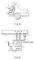
- FIG. 1A and FIG. 1B are figures which show an outline configuration of the mastless antenna test device according to an embodiment of the present invention.
- pane antenna device 2 is allocated on rear window 1 in the vehicle.
- Mastless antenna test device 3 is removably connected to this pane antenna device 2.
- Transmission antenna 4 is placed in mastless antenna test device 3 as shown in FIG. 1B.
- This transmission antenna 4 is an antenna which can selectively transmit various radio waves such as TV wave, AM wave, and FM wave to the pane antenna device 2.
- Pane antenna device 2 and mastless antenna test device 3 are connected by connector group 5 and power supply control connector 6 as shown in FIG. 1B.
- Connector group 5 has connector 5a for the AM/FM antenna signal, connector 5b for the FM-IF signal, connector 5c for the TV antenna signal, and connector 5d for the video signal.
- Indicator 37 and operation switch 38, etc. for displaying the test result described later are arranged in front of the case of the mastless antenna test device 3.
- FIG. 2 is a figure which shows the state of connecting pane antenna device 2 with mastless antenna test device 3 by connectors.
- Pane antenna device 2 has antenna section 2A and attached device section 2B as shown in FIG. 2.
- the antenna section 2A is an antenna element, in which a translucent long and narrow thin film conductor is formed to a predetermined pattern on the pane, and has a TV wave reception antenna 21 (antenna elements TV1 to TV4), an AM wave reception antenna 22 (antenna element AM), and an FM wave reception antenna 23 (antenna elements FM1 to FM4).
- Attached device section 2B is constructed by providing low noise amplifier (LNA) 24, TV diversity circuit 25, FM diversity circuit 26, diversity power supply circuit 27, LNA power supply circuit 28, or the like on the substrate.
- LNA low noise amplifier
- Each of antenna elements TV1 to TV4 of the TV wave reception antenna 21 is connected with TV diversity circuit 25 respectively through above-mentioned low noise amplifier (LNA) 24.
- LNA low noise amplifier
- Each of antenna elements FM1 to FM4 of the FM wave reception antenna 21 is connected with FM diversity circuit 26 respectively through above-mentioned low noise amplifier (LNA) 24.
- LNA low noise amplifier
- the power supply is supplied to TV diversity circuit 25 and FM diversity circuit 26 from diversity power supply circuit 27.
- the power supply is supplied to low noise amplifier (LNA) 24 from LNA power supply circuit 28 through power supply control connector 6.
- LNA low noise amplifier
- Diversity power supply circuit 27 and LNA power supply circuit 28 is constructed to perform the predetermined voltage adjustment etc. for the power supply supplied from on-board battery 29 and output the adjusted result.
- Connector group 5 (connector 5a for the AM/FM antenna signal, connector 5b for the FM-IF signal, connector 5c for the TV antenna signal and connector 5d for the video signal) and power supply control connector 6 are shown in the lower right part of FIG. 2.
- These connector groups 5 and power supply control connector 6 have structures, in which the female side member and the male material side are removably combined, respectively.
- each of female side members is fixed to an end portion of the substrate of attached device section 2B (lower end portion in the figure), and each of the other male side members is attached to an end portion of the connection cable of the test device main body.
- FIG. 2 shows a state that the female side member and the male side member are coupled as one body, that is, shows a test state.
- Connector 5a for the AM/FM antenna signal is connected with FM diversity circuit 26 and low noise amplifier (LNA) 24 provided to element AM of antenna 22 for AM wave.
- Connector 5b for FM-IF signal is connected with FM diversity circuit 26.
- Connector 5c for the TV antenna signal and connector 5d for the video signal are connected with TV diversity circuit 25.
- LNA low noise amplifier
- the jumper connector (not shown) as the male side member is inserted in the female side member of power supply control connector 6, and each pair of terminals is short-circuited. Therefore, at non-test state (at normal usage), the power supply to which is supplied from on-vehicle battery 29 and in which the voltage etc. are adjusted by LNA power supply circuit 28, is simultaneously supplied to each power supply terminal of low noise amplifier (LNA) 24 through power supply control connector 6. Moreover, the wire harness (not shown) as the male side member on the test device main body side is coupled to instead of the jumper connector at test state. As a result, as described later, according to the control of the test device main body, it becomes possible to selectively supply the power supply to each power supply terminal of the low noise amplifier (LNA).
- LNA low noise amplifier
- FIG. 3 is a figure which shows an internal configuration of test device main body 30 in mastless antenna test device 3.
- Test device main body 30 comprises transmission means including transmission antenna 4 which can selectively transmit various radio waves such as the TV wave, AM wave, and FM wave to the antenna section 2A of the pane antenna device 2.
- This transmission means mainly comprises generator 31 which includes the AM transmission section, the FM transmission section, and the TV transmission section, and select switch circuit 32 which selects the output from this generator 31 and sends it to transmission antenna 4.
- Test device main body 30 comprises individual reception means which takes out and receives a specific antenna output among the plurality of antenna outputs obtained from the plurality of antenna elements in the antenna section 2A in response to one kind of radio waves transmitted by the transmission means.
- This individual reception means mainly comprises specifying switch circuit 33 which specifies low noise amplifier 24 to be in the operation state, connection cable 34 which connects between test device main body 30 with the connector group 5 and power supply control connector 6, and receiver 35 which includes the AM receiver, the FM receiver, and the TV receiver to receive the antenna output etc. obtained through the connector group 5 so as to individually take out a specific antenna output (case of only of one channel and case of 1 to 4 channels, etc. are included).
- Test device main body 30 comprises judgment means 36, which judges the quality of the antenna output received by the above-mentioned individual reception means.
- This judgment means 36 is specifically achieved with CPU which is the component of control means 39 to automatically control the transmission means and the individual reception means, and the A/D converter.
- the judgment result by the judgment means 36 is displayed with above-mentioned indicator 37.
- the buzzer etc. for abnormal information may be provided besides this indicator 37.
- Operation switch 38 includes various switches such as the power supply turning on switch, the initialization switch, the test starting switch, and automatic/manual operations switching switch.
- Power supply section 40 is a part to which the power supply to operate each section of test device main body 30 is supplied, and, for example, the battery is used as a power supply.
- the AM/FM ⁇ ANT terminal provided to receiver 35 is a terminal to take the AM/FM antenna output sent from the pane antenna device 2 through the connector 5a
- FM-IF terminal is a terminal to send back the IF signal based on the sent FM antenna output to pane antenna device 2 (FM diversity circuit 26) as a reference signal which shows the reception state of FM wave through the connector 5b
- the TV ⁇ ANT terminal is a terminal to take the TV antenna output sent from the pane antenna device 2 through the connector 5c
- the VIDEO terminal is a terminal to send back a video signal based on the sent TV antenna output to pane antenna device 2 (TV diversity circuit 25) as a reference signal which shows the reception state of the TV wave through the connector 5d.
- test device main body 30 An operation of test device main body 30 is started, and the output of FM transmission section in generator 31 is irradiated through transmission antenna 4 as a radio wave of the frequency which corresponds to the frequency modulation broadcasting frequency.
- the channel specification operation is performed by using operation switch 38 of test device main body 30, to operate specifying switch circuit 33 by operating LNA power supply controller 39b in control means 39, the power supply output from LNA power supply circuit 28 in pane antenna device 2 is supplied to low noise amplifier (LNA) 24 of ch-1 in pane antenna device 2 after passing above-mentioned specifying switch circuit 33.
- LNA low noise amplifier
- FM diversity circuit 26 scans ch-1 to ch-4 cyclically.
- FM wave reception antenna 23 having the antenna elements of ch-1 to ch-4 receives the radio wave from the transmission antenna 4 of test device main body 30, since the power supply is supplied only to the low noise amplifier (LNA) 24 of ch-1, the ch-1 of an input of FM diversity circuit 26 becomes a best condition. That is, it becomes an excellent reception state since the antenna output signal of FM diversity circuit 26 becomes large when FM diversity circuit 26 scans ch-1.
- LNA low noise amplifier
- FM diversity circuit 26 on pane antenna device 2 receives the IF signal which indicates the reception state from FM receiver in receiver 35. of test device main body 30 as a reference signal. And, above-mentioned FM diversity circuit 26 stops scanning of the antenna when judging that the reception is excellent by analyzing above-mentioned IF signal. As a result, the antenna element of excellent reception state is selected. And, ch-1 is judged the test passing if the reception signal level of FM receiver in receiver 35 of test device main body 30 is a range of regulations. This judgment result is displayed on indicator 37 which is the information means. When the test is failed, this result is displayed on indicator 37, the warning with, for example, the buzzer etc. is generated and the test failure is informed. Each test procedure and the judgment, etc. of test device main body 30 are performed by control microcomputer 39a etc. in the test device main body.
- the test of ch-2 to ch-4 is performed in the same way. Since a basic principle of the test of the TV diversity function is similar to that of ch-1, the explanation will be omitted. Moreover, the explanation of the test of the reception function of the AM wave will be omitted since it is similar to the test of the reception function concerning one antenna element of FM wave.
Landscapes
- Physics & Mathematics (AREA)
- Electromagnetism (AREA)
- General Physics & Mathematics (AREA)
- Testing Electric Properties And Detecting Electric Faults (AREA)
- Monitoring And Testing Of Transmission In General (AREA)
- Variable-Direction Aerials And Aerial Arrays (AREA)
Applications Claiming Priority (2)
| Application Number | Priority Date | Filing Date | Title |
|---|---|---|---|
| JP21774298 | 1998-07-31 | ||
| JP10217742A JP2000049719A (ja) | 1998-07-31 | 1998-07-31 | マストレスアンテナ検査装置 |
Publications (1)
| Publication Number | Publication Date |
|---|---|
| EP0977044A1 true EP0977044A1 (de) | 2000-02-02 |
Family
ID=16709053
Family Applications (1)
| Application Number | Title | Priority Date | Filing Date |
|---|---|---|---|
| EP99305752A Withdrawn EP0977044A1 (de) | 1998-07-31 | 1999-07-20 | Prüfvorrichtung für Antennen ohne Mast |
Country Status (2)
| Country | Link |
|---|---|
| EP (1) | EP0977044A1 (de) |
| JP (1) | JP2000049719A (de) |
Cited By (4)
| Publication number | Priority date | Publication date | Assignee | Title |
|---|---|---|---|---|
| EP1065509A3 (de) * | 1999-07-02 | 2001-01-17 | FUBA Automotive GmbH & Co. KG | Diagnosevorrichtung für eine Mehrantennenanordnung |
| WO2001004649A1 (de) * | 1999-07-07 | 2001-01-18 | Robert Bosch Gmbh | Schaltungsanordnung und verfahren zur prüfung eines schaltdiversity-systems |
| US10274743B2 (en) * | 2016-09-27 | 2019-04-30 | Hyundai Motor Company | Imaging system |
| CN111948468A (zh) * | 2019-05-17 | 2020-11-17 | 标致雪铁龙汽车股份有限公司 | 一种车辆emc测试系统及其操作方法 |
Citations (4)
| Publication number | Priority date | Publication date | Assignee | Title |
|---|---|---|---|---|
| JPS6338337A (ja) * | 1986-08-01 | 1988-02-18 | Nec Corp | スペ−スダイバ−シテイ受信機の障害検出方式 |
| GB2272604A (en) * | 1992-11-10 | 1994-05-18 | Motorola Inc | Radio base station with diversity receiver testing. |
| DE19513872A1 (de) * | 1995-04-12 | 1996-10-17 | Fuba Automotive Gmbh | Verfahren und Schaltungsanordnung zum Prüfen von Kraftfahrzeug-Antennen |
| EP0816859A2 (de) * | 1996-07-06 | 1998-01-07 | FLACHGLAS Automotive GmbH | Diagnoseverfahren und Diagnose-system für Kfz-Antennenscheiben |
-
1998
- 1998-07-31 JP JP10217742A patent/JP2000049719A/ja active Pending
-
1999
- 1999-07-20 EP EP99305752A patent/EP0977044A1/de not_active Withdrawn
Patent Citations (4)
| Publication number | Priority date | Publication date | Assignee | Title |
|---|---|---|---|---|
| JPS6338337A (ja) * | 1986-08-01 | 1988-02-18 | Nec Corp | スペ−スダイバ−シテイ受信機の障害検出方式 |
| GB2272604A (en) * | 1992-11-10 | 1994-05-18 | Motorola Inc | Radio base station with diversity receiver testing. |
| DE19513872A1 (de) * | 1995-04-12 | 1996-10-17 | Fuba Automotive Gmbh | Verfahren und Schaltungsanordnung zum Prüfen von Kraftfahrzeug-Antennen |
| EP0816859A2 (de) * | 1996-07-06 | 1998-01-07 | FLACHGLAS Automotive GmbH | Diagnoseverfahren und Diagnose-system für Kfz-Antennenscheiben |
Non-Patent Citations (1)
| Title |
|---|
| PATENT ABSTRACTS OF JAPAN vol. 012, no. 250 (E - 633) 14 July 1988 (1988-07-14) * |
Cited By (5)
| Publication number | Priority date | Publication date | Assignee | Title |
|---|---|---|---|---|
| EP1065509A3 (de) * | 1999-07-02 | 2001-01-17 | FUBA Automotive GmbH & Co. KG | Diagnosevorrichtung für eine Mehrantennenanordnung |
| WO2001004649A1 (de) * | 1999-07-07 | 2001-01-18 | Robert Bosch Gmbh | Schaltungsanordnung und verfahren zur prüfung eines schaltdiversity-systems |
| US6771057B1 (en) | 1999-07-07 | 2004-08-03 | Robert Bosch Gmbh | Circuit arrangement and method for verifying a switching diversity system |
| US10274743B2 (en) * | 2016-09-27 | 2019-04-30 | Hyundai Motor Company | Imaging system |
| CN111948468A (zh) * | 2019-05-17 | 2020-11-17 | 标致雪铁龙汽车股份有限公司 | 一种车辆emc测试系统及其操作方法 |
Also Published As
| Publication number | Publication date |
|---|---|
| JP2000049719A (ja) | 2000-02-18 |
Similar Documents
| Publication | Publication Date | Title |
|---|---|---|
| US5826179A (en) | Multi-antenna scanning diversity system | |
| US6407554B1 (en) | Diagnostic tester for electronic control devices in a variety of motor vehicle types | |
| US6023603A (en) | Satellite signal splitter | |
| US9455494B2 (en) | In-vehicle multimedia device having antenna module and tuner part module integrated therein | |
| KR100338990B1 (ko) | 복수개의안테나와복수개의무선채널유닛을매트릭스접속하기위한모듈상호접속매트릭스 | |
| US6150734A (en) | Electrical distribution system | |
| EP0977044A1 (de) | Prüfvorrichtung für Antennen ohne Mast | |
| US20060205369A1 (en) | Multiple antenna receiver system in vehicles | |
| US20070152675A1 (en) | Diagnostic method for monitoring a plug-in connection | |
| US6870510B2 (en) | Bumper-aerial assembly | |
| US7106263B2 (en) | Window-integrated antenna for LMS and diversitary FM reception in mobile motor vehicles | |
| JP2001102826A (ja) | アンテナ装置およびアンテナシステム | |
| CN212381326U (zh) | 卫星数字电视信号测试装置及系统 | |
| US6771057B1 (en) | Circuit arrangement and method for verifying a switching diversity system | |
| CN112567634A (zh) | 带有集成的发射放大器保护功能的用于无线电信号的发射/接收系统 | |
| KR100957326B1 (ko) | 이동단말에서 디지털 멀티미디어 방송 서비스 수신 장치 및방법 | |
| KR20190100278A (ko) | 동축 케이블과 전기 단자를 포함하는 자동차용 전기 조립체 | |
| US20160212558A1 (en) | Multi-channel Wireless Microphone System | |
| US10700412B2 (en) | Converter device for adapting an antenna impedance, comprising a housing for a motor vehicle, and motor vehicle with converter device installed therein | |
| KR20100003075U (ko) | 후방감시 카메라결합형 차량용 외장 안테나 장치 | |
| JP2005297761A (ja) | 車載カメラ映像伝送システム | |
| JP3947031B2 (ja) | 衛星信号受信伝送システム及び切替分配器 | |
| US5991597A (en) | Converter for a satellite signal receiving antenna | |
| JPH0434568Y2 (de) | ||
| EP0947391B1 (de) | Elektrisches Verteilungssystem |
Legal Events
| Date | Code | Title | Description |
|---|---|---|---|
| PUAI | Public reference made under article 153(3) epc to a published international application that has entered the european phase |
Free format text: ORIGINAL CODE: 0009012 |
|
| 17P | Request for examination filed |
Effective date: 19990810 |
|
| AK | Designated contracting states |
Kind code of ref document: A1 Designated state(s): AT BE CH CY DE DK ES FI FR GB GR IE IT LI LU MC NL PT SE |
|
| AX | Request for extension of the european patent |
Free format text: AL;LT;LV;MK;RO;SI |
|
| AKX | Designation fees paid |
Free format text: AT BE CH CY DE DK ES FI FR GB GR IE IT LI LU MC NL PT SE |
|
| 17Q | First examination report despatched |
Effective date: 20030918 |
|
| STAA | Information on the status of an ep patent application or granted ep patent |
Free format text: STATUS: THE APPLICATION IS DEEMED TO BE WITHDRAWN |
|
| 18D | Application deemed to be withdrawn |
Effective date: 20040330 |