EP0977215A2 - Verbinderanordnung zum Laden eines elektrischen Fahrzeugs - Google Patents
Verbinderanordnung zum Laden eines elektrischen Fahrzeugs Download PDFInfo
- Publication number
- EP0977215A2 EP0977215A2 EP99122516A EP99122516A EP0977215A2 EP 0977215 A2 EP0977215 A2 EP 0977215A2 EP 99122516 A EP99122516 A EP 99122516A EP 99122516 A EP99122516 A EP 99122516A EP 0977215 A2 EP0977215 A2 EP 0977215A2
- Authority
- EP
- European Patent Office
- Prior art keywords
- side connector
- power
- core
- present
- magnets
- Prior art date
- Legal status (The legal status is an assumption and is not a legal conclusion. Google has not performed a legal analysis and makes no representation as to the accuracy of the status listed.)
- Withdrawn
Links
Images











Classifications
-
- H—ELECTRICITY
- H01—ELECTRIC ELEMENTS
- H01R—ELECTRICALLY-CONDUCTIVE CONNECTIONS; STRUCTURAL ASSOCIATIONS OF A PLURALITY OF MUTUALLY-INSULATED ELECTRICAL CONNECTING ELEMENTS; COUPLING DEVICES; CURRENT COLLECTORS
- H01R13/00—Details of coupling devices of the kinds covered by groups H01R12/70 or H01R24/00 - H01R33/00
- H01R13/62—Means for facilitating engagement or disengagement of coupling parts or for holding them in engagement
- H01R13/6205—Two-part coupling devices held in engagement by a magnet
-
- B—PERFORMING OPERATIONS; TRANSPORTING
- B60—VEHICLES IN GENERAL
- B60L—PROPULSION OF ELECTRICALLY-PROPELLED VEHICLES; SUPPLYING ELECTRIC POWER FOR AUXILIARY EQUIPMENT OF ELECTRICALLY-PROPELLED VEHICLES; ELECTRODYNAMIC BRAKE SYSTEMS FOR VEHICLES IN GENERAL; MAGNETIC SUSPENSION OR LEVITATION FOR VEHICLES; MONITORING OPERATING VARIABLES OF ELECTRICALLY-PROPELLED VEHICLES; ELECTRIC SAFETY DEVICES FOR ELECTRICALLY-PROPELLED VEHICLES
- B60L53/00—Methods of charging batteries, specially adapted for electric vehicles; Charging stations or on-board charging equipment therefor; Exchange of energy storage elements in electric vehicles
- B60L53/10—Methods of charging batteries, specially adapted for electric vehicles; Charging stations or on-board charging equipment therefor; Exchange of energy storage elements in electric vehicles characterised by the energy transfer between the charging station and the vehicle
- B60L53/12—Inductive energy transfer
- B60L53/126—Methods for pairing a vehicle and a charging station, e.g. establishing a one-to-one relation between a wireless power transmitter and a wireless power receiver
-
- B—PERFORMING OPERATIONS; TRANSPORTING
- B60—VEHICLES IN GENERAL
- B60L—PROPULSION OF ELECTRICALLY-PROPELLED VEHICLES; SUPPLYING ELECTRIC POWER FOR AUXILIARY EQUIPMENT OF ELECTRICALLY-PROPELLED VEHICLES; ELECTRODYNAMIC BRAKE SYSTEMS FOR VEHICLES IN GENERAL; MAGNETIC SUSPENSION OR LEVITATION FOR VEHICLES; MONITORING OPERATING VARIABLES OF ELECTRICALLY-PROPELLED VEHICLES; ELECTRIC SAFETY DEVICES FOR ELECTRICALLY-PROPELLED VEHICLES
- B60L53/00—Methods of charging batteries, specially adapted for electric vehicles; Charging stations or on-board charging equipment therefor; Exchange of energy storage elements in electric vehicles
- B60L53/30—Constructional details of charging stations
- B60L53/34—Plug-like or socket-like devices specially adapted for contactless inductive charging of electric vehicles
-
- H—ELECTRICITY
- H01—ELECTRIC ELEMENTS
- H01F—MAGNETS; INDUCTANCES; TRANSFORMERS; SELECTION OF MATERIALS FOR THEIR MAGNETIC PROPERTIES
- H01F38/00—Adaptations of transformers or inductances for specific applications or functions
- H01F38/14—Inductive couplings
-
- H—ELECTRICITY
- H02—GENERATION; CONVERSION OR DISTRIBUTION OF ELECTRIC POWER
- H02J—ELECTRIC POWER NETWORKS; CIRCUIT ARRANGEMENTS OR SYSTEMS FOR SUPPLYING OR DISTRIBUTING ELECTRIC POWER; SYSTEMS FOR STORING ELECTRIC ENERGY
- H02J50/00—Circuit arrangements or systems for wireless supply or distribution of electric power
- H02J50/10—Circuit arrangements or systems for wireless supply or distribution of electric power using inductive coupling
-
- B—PERFORMING OPERATIONS; TRANSPORTING
- B60—VEHICLES IN GENERAL
- B60L—PROPULSION OF ELECTRICALLY-PROPELLED VEHICLES; SUPPLYING ELECTRIC POWER FOR AUXILIARY EQUIPMENT OF ELECTRICALLY-PROPELLED VEHICLES; ELECTRODYNAMIC BRAKE SYSTEMS FOR VEHICLES IN GENERAL; MAGNETIC SUSPENSION OR LEVITATION FOR VEHICLES; MONITORING OPERATING VARIABLES OF ELECTRICALLY-PROPELLED VEHICLES; ELECTRIC SAFETY DEVICES FOR ELECTRICALLY-PROPELLED VEHICLES
- B60L2270/00—Problem solutions or means not otherwise provided for
- B60L2270/30—Preventing theft during charging
- B60L2270/32—Preventing theft during charging of electricity
-
- B—PERFORMING OPERATIONS; TRANSPORTING
- B60—VEHICLES IN GENERAL
- B60L—PROPULSION OF ELECTRICALLY-PROPELLED VEHICLES; SUPPLYING ELECTRIC POWER FOR AUXILIARY EQUIPMENT OF ELECTRICALLY-PROPELLED VEHICLES; ELECTRODYNAMIC BRAKE SYSTEMS FOR VEHICLES IN GENERAL; MAGNETIC SUSPENSION OR LEVITATION FOR VEHICLES; MONITORING OPERATING VARIABLES OF ELECTRICALLY-PROPELLED VEHICLES; ELECTRIC SAFETY DEVICES FOR ELECTRICALLY-PROPELLED VEHICLES
- B60L2270/00—Problem solutions or means not otherwise provided for
- B60L2270/30—Preventing theft during charging
- B60L2270/34—Preventing theft during charging of parts
-
- Y—GENERAL TAGGING OF NEW TECHNOLOGICAL DEVELOPMENTS; GENERAL TAGGING OF CROSS-SECTIONAL TECHNOLOGIES SPANNING OVER SEVERAL SECTIONS OF THE IPC; TECHNICAL SUBJECTS COVERED BY FORMER USPC CROSS-REFERENCE ART COLLECTIONS [XRACs] AND DIGESTS
- Y02—TECHNOLOGIES OR APPLICATIONS FOR MITIGATION OR ADAPTATION AGAINST CLIMATE CHANGE
- Y02T—CLIMATE CHANGE MITIGATION TECHNOLOGIES RELATED TO TRANSPORTATION
- Y02T10/00—Road transport of goods or passengers
- Y02T10/60—Other road transportation technologies with climate change mitigation effect
- Y02T10/70—Energy storage systems for electromobility, e.g. batteries
-
- Y—GENERAL TAGGING OF NEW TECHNOLOGICAL DEVELOPMENTS; GENERAL TAGGING OF CROSS-SECTIONAL TECHNOLOGIES SPANNING OVER SEVERAL SECTIONS OF THE IPC; TECHNICAL SUBJECTS COVERED BY FORMER USPC CROSS-REFERENCE ART COLLECTIONS [XRACs] AND DIGESTS
- Y02—TECHNOLOGIES OR APPLICATIONS FOR MITIGATION OR ADAPTATION AGAINST CLIMATE CHANGE
- Y02T—CLIMATE CHANGE MITIGATION TECHNOLOGIES RELATED TO TRANSPORTATION
- Y02T10/00—Road transport of goods or passengers
- Y02T10/60—Other road transportation technologies with climate change mitigation effect
- Y02T10/7072—Electromobility specific charging systems or methods for batteries, ultracapacitors, supercapacitors or double-layer capacitors
-
- Y—GENERAL TAGGING OF NEW TECHNOLOGICAL DEVELOPMENTS; GENERAL TAGGING OF CROSS-SECTIONAL TECHNOLOGIES SPANNING OVER SEVERAL SECTIONS OF THE IPC; TECHNICAL SUBJECTS COVERED BY FORMER USPC CROSS-REFERENCE ART COLLECTIONS [XRACs] AND DIGESTS
- Y02—TECHNOLOGIES OR APPLICATIONS FOR MITIGATION OR ADAPTATION AGAINST CLIMATE CHANGE
- Y02T—CLIMATE CHANGE MITIGATION TECHNOLOGIES RELATED TO TRANSPORTATION
- Y02T90/00—Enabling technologies or technologies with a potential or indirect contribution to GHG emissions mitigation
- Y02T90/10—Technologies relating to charging of electric vehicles
- Y02T90/12—Electric charging stations
-
- Y—GENERAL TAGGING OF NEW TECHNOLOGICAL DEVELOPMENTS; GENERAL TAGGING OF CROSS-SECTIONAL TECHNOLOGIES SPANNING OVER SEVERAL SECTIONS OF THE IPC; TECHNICAL SUBJECTS COVERED BY FORMER USPC CROSS-REFERENCE ART COLLECTIONS [XRACs] AND DIGESTS
- Y02—TECHNOLOGIES OR APPLICATIONS FOR MITIGATION OR ADAPTATION AGAINST CLIMATE CHANGE
- Y02T—CLIMATE CHANGE MITIGATION TECHNOLOGIES RELATED TO TRANSPORTATION
- Y02T90/00—Enabling technologies or technologies with a potential or indirect contribution to GHG emissions mitigation
- Y02T90/10—Technologies relating to charging of electric vehicles
- Y02T90/14—Plug-in electric vehicles
Definitions
- the present invention relates to charging connectors for an electric vehicle as those for use in charging the storage battery of such an electric vehicle.
- Charging connectors for an electric vehicle as those for use in charging the storage battery of the electric vehicle include a vehicle-side connector which is connected to the storage battery mounted in a vehicle body and also fastened to the vehicle body, and a power-supply-side connector which is connected to a power supply for supplying charging electric power.
- the charging operation is performed in such a state that the power-supply-side connector has been fitted in the vehicle-side connector.
- the power-supply-side connector is then detached from the vehicle-side connector.
- charging connectors are generally of such a type that the operations of connecting and disconnecting the connectors are manually performed, charging work has to be done smoothly in particular.
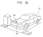
- U.S. Patent No. 5,408,209 describes a coupling apparatus of the sort mentioned above and as shown in Fig. 26, a slit 102 is formed in the predetermined position of the body of an electric vehicle 101 and a charging coupler 103 is made insertable in the slit 102.
- a coupler accommodating portion 104 of the charging coupler 103 is provided under the slit 102.
- the coupler accommodating portion 104 is equipped with a secondary core 105, a secondary coil 106 which is wound on the secondary core 105 and a channel 107 which is formed in the secondary core 105 and used for receiving the charging coupler 103.
- the charging coupler 103 is equipped with a primary core 108 and a primary coil 109 which is wound on the primary core 108 and the primary coil 109 is excited by a charging power supply.
- electromotive force is generated in the secondary coil 106, whereby the power battery (not shown) of such an electric vehicle is charged.
- the charging coupler 103 is inserted via the slit 102 in the channel 107 from above and taken out of the coupler accommodating portion 104 again by pulling it upward with a handle 103A on the termination of the charging operation.
- the joint surfaces of the cores are exposed to the air when they are not used, though they are brought into engagement with each other at the time of charging. Consequently, extraneous substances may stick to the joint surfaces.
- the extraneous substances sticking to the joint surfaces 105A, 105A (see Fig. 27) of the secondary core 105 cannot easily be found nor cleaned because the secondary core 105 is situated in the depth of the coupler accommodating portion 104.
- the secondary core 105 has two joint surfaces 105A which are directed opposite to each other and the trouble is that the work of cleaning them has to be done twice by changing the direction of the cleaning means.
- An object of the present invention made in consideration of the situation mentioned above is to effect improvement in workability when a power-supply-side connector is fitted in and detached from a vehicle-side connector.
- An another object of the present invention made in view of the foregoing problems is to facilitate the work of finding extraneous substances sticking to joint surfaces of cores and cleaning them.
- the magnetic force generated between the connector holding magnets and the magnetic material is utilized for bringing the charging connector and the other connector into engagement with each other. Consequently, the charging connector is prevented from being inadvertently detached from the other connector and thus the work of charging the storage battery is smoothly done.
- the object of the present invention is achieved by providing a magnetic coupling apparatus for charging the power batter of an electric vehicle by means of an external charging power supply including: a primary core with a primary coil which is wound on the primary core, coupled to the external charging power supply and a secondary core with a secondary coil which is wound on the secondary core, coupled to the power battery, said primary and secondary cores being jointable to one another so as to constitute a closed loop magnetic circuit, wherein the secondary core is accommodated in a recess so formed as to have an open portion in the exterior of the electric vehicle, and the joint surfaces of the secondary core jointing the primary core are formed in the open portion side of the recess.
- the joint surfaces of the secondary core are directed to the open portion of the recess and consequently the joint surfaces of the secondary core communicate with the outside of the electric vehicle via the open portion of the recess while the secondary core is not used. Therefore, the operator is allowed to readily find extraneous substances sticking to the joint surfaces from the outside of the electric vehicle and to do the work of cleaning the joint surfaces by holding cleaning means thereto.
- a magnetic coupling apparatus for charging the power battery of an electric vehicle is an apparatus which is equipped with a vehicle-side connector 10 provided so as to fix to the body B of an electric vehicle, and connected to a power battery (not shown) mounted in the electric vehicle and a power-supply-side connector 20 connected to an external power supply (not shown) provided separately from the electric vehicle.
- a connecting recess 11A (“recess” according to the present invention) is provided by making hollow the exterior surface of the body B of the electric vehicle so as to make the connecting recess 11A a connector housing 11 for a vehicle-side connector 10.
- a base plate 12 is fixedly installed in the connector housing 11, and a disk-like core 13 is fastened to the base plate 12.
- a concentric annular coil accommodating portion 14 is formed in the joint surfaces of the core 13 with respect to the power-supply-side connector 20 and a secondary coil 15 is wound on the coil accommodating portion 14.
- the joint surface of the core 13 is divided by the coil accommodating portion 14 into two sides: the central and outer joint surfaces of the core 13 and these two joint surfaces 13A, 13B (see Fig. 2) are connected to the core 23 of the power-supply-side connector 20 at the time charging.
- the joint surfaces 13A, 13B are adapted side by side to form the same plane and directed to the open portion of the connecting recess 11A.
- a concentric annular mounting plate 16 is fixed to the peripheral edge portion of the base plate 12 in such a way as to surround the core 13, and a group of permanent magnets 17 having a plurality (16 pieces according to this embodiment of the present invention) of permanent magnets 17A are provided on the mounting plate 16. As shown in Fig. 2, the group of permanent magnets 17 are arranged so that the N and S poles of 16 pieces of permanent magnets 17A are alternately disposed in a circle with an equal-angle pitch on the one side of the core 13 facing the power-supply-side connector 20.
- a projection 18 is formed on the outer peripheral face of each permanent magnet 17A and the group of permanent magnets 17 are fastened to the base plate 12 by pressing the projections 18 toward the base plate 12 with an annular hold-down member 19 fitted to the outer peripheral edge of the mounting plate 16.
- the power-supply-side connector 20 is equipped with a connector housing 21 which is opened toward the vehicle-side connector 10, and a disk-like core 23 is fastened to a base plate 22 which is fixed to the connector housing 21.
- a concentric annular coil accommodating portion 24 is formed on one side of the core 23, which side is facing the vehicle-side connector 10, and a primary coil 15 is accommodated in the coil accommodating portion 24 in such a state that the primary coil 25 is wound thereon.
- a concentric annular mounting plate 26 is fixed to the peripheral edge portion of the base plate 22 in such a way as to surround the core 23, and a group of permanent magnets 27 are provided on the mounting plate 26.
- the group of permanent magnets 27 are arranged so that the N and S poles of 16 pieces of permanent magnets 27A are alternately disposed in a circle with an equal-angle pitch on the one side of the core 23 facing the vehicle-side connector 10.
- the diameter of a circle on which the group of permanent magnets 27 are arranged is set equal to that of the circle on which the group of permanent magnets 17 are arranged.
- the group of permanent magnets 27 are fixed to the base plate 22 by holding down a projection 28 formed on the outer peripheral face of the group thereof with an annular hold-down member 29.
- the cores 13, 23 of both connectors 10, 20 correspond to each other and so do the primary and secondary coils 25, 15.
- a trigger 20T is operated in the condition above, the primary coil 25 is excited as current flows from the charging power supply to the power-supply-side connector 20 and a magnetic circuit passing through both coils 15, 25 is formed, whereby the storage battery is charged with the electromagnetic induction current generated in the secondary coil 15.
- the vehicle-side connector 10 and the power-supply-side connector 20 are kept into contact with each other during the charging operation due to the magnetic attraction generated in between the heteropolar magnets in both groups of permanent magnets 17, 27.
- the magnetic attraction causes their facing sides to draw one another, and the position and posture of the power-supply-side connector 20 with respect to the vehicle-side connector 10 are corrected so that the N and S poles of the groups of permanent magnets 17, 27 face one another.
- the fitting operation above is completed at the time both permanent magnets 17, 27 are brought into intimate contact with one another to ensure that the power-supply-side connector 20 is kept in contact with the vehicle-side connector 10 while the free play of the former against the latter is regulated.
- the N and S poles of the groups of permanent magnets 17, 27 thus arranged with the equal-angle pitch amount to eight (8) ways in combination, respectively, there are eight (8) kinds of postures (positions in the circumferential direction) where the power-supply-side connector 20 can be fitted in the vehicle-side connector 10. Since the circumferential posture is not restricted according to this embodiment of the present invention which utilizes the function of the electromagnetic induction, however, it is possible to charge the power-supply-side connector 20 that has been fitted in any posture.
- the magnetic attraction generated between the permanent magnets 17A, 27A causes their facing sides automatically attract one another when the power-supply-side connector 20 is fitted in the vehicle-side connector 10, whereby the fitting work is facilitated. Further, the magnetic repulsive force generated between the permanent magnets 17A, 27A is utilized when they are separated, so that improvement in the work of separating both connectors 10, 20 can also be effected.
- the joint surfaces of both cores 13, 23 are coupled together as they constitute the closed-loop magnetic circuit at the time of charging.
- these joint surfaces are exposed to the air while they are not used, extraneous substances may stick to the joint surfaces.
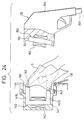
- the joint surfaces 13A, 13B of the secondary coil 13 are directed to the open portion of the connecting recess 11A according to this embodiment of the present invention, the joint surfaces 13A, 13B of the secondary core 13 that are not used are in such a state that they communicate with the exterior of the electric vehicle via the open portion of the connecting recess 11A. Therefore, the operator is able to find extraneous substances sticking to the joint surfaces 13A, 13B easily from the outside of the electric vehicle. As shown in Fig.
- cleaning work can easily be done by applying cleaner to the joint surfaces from the outside of the electric vehicle. Since the joint surfaces 13A, 13B are adapted side by side to form the same plane, it is possible to clean the two joint surfaces 13A, 13B at a time by sliding a cleaner S on the same plane as shown in Fig. 3. Therefore, cleaning work can be done efficiently without the necessity of doing such cleaning work twice by changing the direction of the cleaner as before.
- Extraneous substances sticking to the joint surfaces of the core of the connector according to this embodiment of the present invention can easily be found and removed through cleaning work.
- a cover may be provided for the recess (connecting recess 11A) according to this embodiment of the present invention, so that no extraneous substances are allowed to enter the recess that is not used.
- Embodiment 2 of the present invention is different from Embodiment 1 thereof in that part of the structure of a vehicle-side connector in Embodiment 2 thereof is made different from what is shown in Embodiment 1 and so is the structure of a power-supply-side connector. Consequently, like reference characters are given to like structure, functions and effect of Embodiment 1 of the present invention, and the description thereof will be omitted.
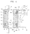
- the vehicle-side connector 10 in Embodiment 2 of the present invention is provided with eight (8) positioning pins (positioning units as component requirements of the present invention) 19A projecting from the hold-down member 19 on the facing sides.
- the positioning pins 19A are arranged with an equal-angle pitch concentrically along the group of permanent magnets 17. Since the rest of the structure of the vehicle-side connector 10 is the same as that of the vehicle-side connector 10 in Embodiment 1 of the present invention, the description thereof will be omitted.
- a power-supply-side connector 30 is equipped with a connector housing 31 which is opened toward the vehicle-side connector 10, and a disk-like core 33 is fixed to a base plate 32 which is fixed to the partition wall 31A of the connector housing 31.
- a concentric annular coil accommodating portion 34 is formed on one side of the core 33, which side is facing the vehicle-side connector 10, and a primary coil 35 is accommodated in a coil accommodating portion 34 in such a state that the primary coil 35 is wound thereon.
- a concentric annular mounting plate 36 is provided on the peripheral edge portion of the partition wall 31A in such a way as to surround the core 33.
- the mounting plate 36 is equipped with ball bearings 36A, which are mounted in such a state that the ball bearings 36A are held between the partition wall 31A and a hold-down member 39 that is fixed to the partition wall 31A, and rotated concentrically with the connector housing 31 by engaging the ball bearings 36A with guide rails 31B, 39A which are arcuate in cross section and formed concentrically with the partition wall 31A and the hold-down member 39.
- a group of permanent magnets 37 are fastened to the hold-down member 39, the group of permanent magnets 37 having 16 pieces of permanent magnets 37A whose N and S poles are alternately disposed in a circle with an equal-angle pitch.
- the group of permanent magnets 37 of the power-supply-side connector 30 are set rotatable with respect to the connector housing 31.
- the engagement releasing unit 40 for facilitating the removal of the power-supply-side connector 30 from the vehicle-side connector 10 is also provided for the power-supply-side connector 30.
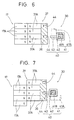
- the engagement releasing unit 40 includes an L-shaped guide groove 41 which is formed in the connector housing 31, a slider 42 which is fitted in the guide groove 41, retaining pins 43 which are provided for the slider 42, and retaining holes 44 which are formed in a mounting plate 36.
- the guide groove 41 has a locking portion 41A and an operating portion 41B which intersect each other perpendicularly and in such a state that the slider 42 is positioned in the locking portion 41A, the retaining pins 43 are removed from the respective retaining holes 44 and become retracted so as not to interfere with the mounting plate 36 as shown in Fig. 6.
- the retaining pins 43 are fitted in the retaining holes 44 and when the slider 42 is moved up in this state as shown in Fig. 7, the group of permanent magnets 37 of the power-supply-side connector 30 together with the mounting plate 36 are shifted by one pitch (equivalent to one permanent magnet).
- the retaining holes 44 correspond to the alternate eight permanent magnets 37A out of the 16 permanent magnets 37A and are arranged with the equal-angle pitch, whereby the retaining pins 43 are made to face the respective retaining holes 44 when the heteropolar magnets in both groups of permanent magnets 17, 37 correspond one another.
- the slider 42 is positioned in the locking portion 41A beforehand and in this state, the power-supply-side connector 30 is set closer to the vehicle-side connector 10 so as to fit the positioning pins 19A in the respective positioning holes 39B.
- both connector housings 11, 31 are properly positioned and their relative floating on facing sides are regulated.
- the N and S poles of the group of permanent magnets 37 of the power-supply-side connector 30 are turned and caused to face the S and N poles of the group of permanent magnets 17 of the vehicle-side connector 10.
- the positioning pins 43 are off the respective positioning holes 44 at this time, the positioning pins 43 are prevented from interfering with the rotation of the group of permanent magnets 37.
- the magnetic attraction generated in between both groups of permanent magnets 17, 37 keeps both connectors 10, 30 fitting each other.
- the positioning pins 19A and the positioning holes 39B are arranged with the equal-angle pitch when the power-supply-side connector 30 is fitted in, there are eight ways of positioning the power-supply-side connector 30 with respect to the vehicle-side connector 10. Since the group of permanent magnets 37 of the power-supply-side connector 30 are freely rotatable, however, the heteropolar magnets in both groups of permanent magnets 17, 37 are allowed to correspond one another in any arrangement and the magnetic attraction generated in this state has both connectors 10, 30 fitted together with ease.
- the slider 42 When the power-supply-side connector 30 is detached from the vehicle-side connector 10, the slider 42 is moved from the locking portion 41A to the operating portion 41B to have the retaining pins 43 fitted in the retaining holes 44 and then the slider 42 is moved upward of Fig. 5 within the operating portion 41B. Since the group of permanent magnets 37 of the power-supply-side connector 30 together with the slider 42 are moved upward by one pitch, the permanent magnets 37A, 17A having the homopolar in both power-supply-side connector 30 and vehicle-side connector 10 correspond to one another. Thus, there is generated the magnetic repulsive force between both groups of permanent magnets 17, 37 and the power-supply-side connector 30 receives pushing back force from the vehicle-side connector 10, so that the former is easily detached from the latter.
- Embodiment 3 of the present invention the engagement releasing unit is made different from what is shown in Embodiment 2 thereof and the rest of the structure is the same as that in Embodiment 2 thereof. Consequently, like reference characters are given to like structure, functions and effect of Embodiment 2 of the present invention, and the description thereof will be omitted.
- An engagement releasing unit 50 in Embodiment 3 of the present invention includes a linear guide groove 51 which is formed in the connector housing, a slider 52 which is fitted in the guide groove 51, a driving cam 53 which is provided for the slider 52, and driven cams 54 which is provided for the mounting plate 36.
- the driven cams 54 correspond to eight alternate permanent magnets 37A out of the 16 permanent magnets 37A and are arranged at equal-angle intervals, so that the driving cam 53 corresponds to any one of the driven cams 54 when the heteropolar magnets in both groups of permanent magnets 17, 37 correspond to one another.
- the driving cam 53 and the driven cams 54 each have cam faces 53A, 54A which tilt in the rotational direction of the group of permanent magnets 37 of the power-supply-side connector 30.
- the slider 52 When the power-supply-side connector 30 is fitted in the vehicles-side connector 10, the slider 52 becomes retracted as shown in Fig. 8 and the tip of the driving cam 53 is so positioned as not to interfere with the driven cams 54, whereby the rotation of the group of permanent magnets 37 are set free from being impeded.
- Embodiment 4 of the present invention the engagement releasing unit is made different from what is shown in Embodiment 2 thereof and the rest of the structure is the same as that in Embodiment 2 thereof. Consequently, like reference characters are given to like structure, functions and effect of Embodiment 2 of the present invention, and the description thereof will be omitted.
- An engagement releasing unit 60 in Embodiment 4 of the present invention includes a trigger 62 which is fitted to the connector housing 31 and capable of rocking operation by means of a support shaft 61, a driving link 63 which is capable of rotation together with the trigger 62 and extended in the opposite direction of the support shaft 61, an L-shaped driven link 65 which is disposed between the driving link 63 and the group of permanent magnets 37 and made rotatable by a support shaft 64, a coupling link 66 for coupling the tip of the driving link 63 to one end of the driven link 65, a retaining pawl 67 which is formed at the other end of the driven link 65, and a retaining recess 68 which is formed in the mounting plate 36.
- the trigger 62 When the power-supply-side connector 30 is fitted in, the trigger 62 is in a prior-to-operating position, and the retaining pawl 67 of the driven link 65 is released from the retaining recess 68 and set free from interfering with the mounting plate 36 as shown in Fig. 10, whereby the group of permanent magnets 37 is made rotatable without any obstacle.
- Figs. 12 to 15 show Embodiment 5 of the present invention wherein the structure of magnets for use in bringing both connectors into engagement with each other is different from what is shown in Embodiment 1 of the present invention.
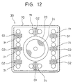
- a connector housing 70 of the power-supply-side connector 30 according to this embodiment of the present invention is rectangular as shown in Fig. 12. In the center of the rectangle is the same core 23 as that in Embodiment 1 of the present invention and a plurality of connector holding magnets 71 are arranged in the peripheral edge portion.
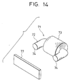
- the connector holding magnet 71 is an electromagnet such that, as shown in Fig. 14, a coil 73 is wound in the intermediate portion of a ferrite core 72 which is formed by bending a round bar into an angular C-shape and mounted in the connector housing 70 so that both edge faces 74, 74 of the magnetic core 72 and the core 23 are leveled (see Fig. 13).
- a slide switch 75 (see Fig. 13) installed on the back of a grip 20G is used for switching an excitation state over to a non-excitation state and vice versa.
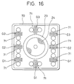
- the plurality of connector holding magnets 71 are arranged as shown in Fig. 12 so that three of them are disposed along both lateral sides of the rectangular connector housing 70 and each one of them is also disposed in the center of upper and lower sides thereof.
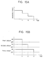
- these connector holding magnets 71 are divided into three groups and released from the excitation state successively in order. More specifically, the first group (see symbol G1 of Fig. 12) consists of the magnets on both upper end sides and the central lower side of the connector housing 70; the second group (see symbol G2 of Fig. 12) consists of the magnets on both lower end sides and the central upper side thereof; and the third group (see symbol G3 of Fig.
- the vehicle-side connector is equipped with a rectangular base portion 76 inside a rectangular connector housing 79 corresponding to the aforementioned connector housing 70 (see Fig. 13).
- a rectangular base portion 76 In the center of the base portion 76 is the same core 13 as that in Embodiment 1 of the present invention and a plurality of metal plates 77 (corresponding to the magnetic material according to the present invention) are mounted on portions facing the connector holding magnets 71 out of the base portion 76.
- the metal plates 77 are joined in such a way as to crosslink both end portions of the connector holding magnets 71 (see Fig. 14). Since the remaining structure is the same as what is shown in Embodiment 1 of the present invention, the description thereof will be omitted.
- the power-supply-side connector 30 When charging work is done, the power-supply-side connector 30 is joined to the vehicle-side connector 10 and the slide switch 75 is turned on. Since the whole connector holding magnets 71 is excited and attracts the metal plate 77, the connectors are kept into engagement with each other even thought the operator loosens his hold of the grip 20G, whereby the power-supply-side connector 30 is prevented from being inadvertently detached from the vehicle-side connector 10 during the charging operation.
- the slide switch 75 is turned off. Then the plurality of connector holding magnets 71 are released from the magnetic force in the order of the first, second and third groups as shown in Fig. 15(B) and as this process proceeds, the attractive force between both connectors 10, 30 is gradually weakened as shown in Fig. 15(A). Then the weight load of the connector 10 is gradually increased on the part of the operator holding the grip 20G, whereby the detaching operation is smoothly performed as the preparation of detaching the power-supply-side connector can be made.
- the connector holding magnets 71 are released from excitation on a three group basis as shown in Fig. 16. More specifically, a first group (see symbol G1 of Fig. 16) consists of three magnets in the lower portion of the connector housing 70; a second group (see symbol G2 of Fig. 16) consists of two magnets in both side portions; and a third group (see symbol G3 of Fig. 16) consists of three magnets in the upper portion.
- the timer attached to the power supply operates to cut off the voltage applied to the coil 73 of each electromagnet in the order of the first, second and third groups at predetermined time intervals.
- the excitation is released.
- the power-supply-side connector 30 can be detached from the vehicle-side connector 10 successively from the lower portion of the joint surface toward the upper portion, the operator is allowed to do the work of detaching the former from the latter smoothly as if he gradually peels off the former without receiving the load which suddenly increases.
- the connector holding magnets 71 are successively excited in the order of the third, second and first groups so that both connectors may be joined successively.
- Embodiment 7 of the present invention referring to Figs. 17 to 19, a recess which is provided with a cover and a core different in type from the core in Embodiment 1 of the present invention are shown by way of example.
- a receptacle 130 (recess" according to the present invention) outwardly opened is formed in the exterior surface of the body of an electric vehicle and the opening can be opened and closed with a cover 131 and besides a secondary coil unit 140 is placed therein. Further, a coupler 132 attached to one end of a charging power cable 133 extended from an external charging apparatus (not shown) can be fitted in along an arrow A of Fig. 17.
- a secondary coil unit 140 is formed by winding a secondary coil 142 on a secondary core 141 of ferrite, for example, and the output terminal of the secondary coil 142 is connected to a charging circuit for charging a power battery (not shown) as the power battery of an electric vehicle, so that the power battery can be charged by rectifying the high-frequency electromotive force in the secondary coil 142.
- the secondary core 141 is formed by, for example, bending a quadrangular prism into an angular C-shape and the secondary coil 142 is wound on the vertical side 141A of the C-shape, and the opposed sides 141B, 141B horizontally extending forward from the respective ends of the vertical side 141A have the same length.
- the front edge faces of the opposed sides 141B, 141B form joint surfaces 143, 143 with respect to the primary core 151 which will be described later and are mutually positioned on the same plane and also directed to the open portion of the receptacle 130.
- the coupler 132 is equipped with a housing 134 which is insertable in the receptacle 130 and contains a primary coil unit 150 including a primary coil 152 and a primary core 151.
- the primary core 151 is I-shaped and its forward-turned sides out of both end sides form joint surfaces 153, 153 (see Fig. 18) with respect to the secondary core 141 and the primary coil 152 is wound on a place closer to the central part than the joint surfaces 153, 153.
- One end of the primary coil 152 is connected to the charging power cable 133.
- a through-hole 135 (see Fig. 18) is formed in a portion opposite to the joint surface 153 of the primary core 151 out of the joint surfaces of the housing 134 and when the coupler 132 is inserted in the receptacle 130, the opposed sides 141B of the secondary core 141 are introduced into the housing 134 via the through-hole 135 and further both joint surfaces 143, 153 are brought into contact with each other.
- a closed loop magnetic circuit by means of both cores 141, 151 are formed and when the primary coil 152 is excited through the charging power cable 133, electromotive force is generated in the secondary coil 142, whereby the power battery of an electric vehicle is charged.
- the open edge portion of the receptacle 130 is provided with a lock portion 136 for mechanically locking the primary coil unit 150 in the receptacle 130 in order to prevent the primary coil unit 150 from inadvertently falling away.
- Embodiment 7 of the present invention is thus constituted and functions as follows:
- the cover 131 is normally closed to prevent extraneous substances from entering the receptacle 130.
- the receptacle 130 is made open.
- the joint surfaces 143, 143 of the secondary core 141 are directed to the open portion of the receptacle 130, they communicate with the outside of the electric vehicle via the open portion of the receptacle 130. Therefore, as in Embodiment 1 of the present invention, extraneous substances sticking to the joint surfaces 143, 143 of the secondary core 141 can easily be found and removed through cleaning work (see Fig. 19).
- the charging operation is performed in normal condition with the joint surfaces 143, 143 free from any extraneous substances.
- the cover 131 is closed to stop extraneous substances from entering the receptacle 130.
- Embodiment 8 of the present invention is shown in Figs. 20 to 22. Although it has been arranged that the joint surfaces of the secondary core are adapted side by side to form the same plane in Embodiments 1, 7, the joint surfaces are not necessarily formed on the same plane and in Embodiment 8 of the present invention, the joint surfaces of the secondary core are not formed on the same plane.
- Like reference characters are given to like structure, functions and effect of Embodiment 7 of the present invention, and the description thereof will be omitted.
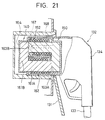
- a secondary core 161 according to this embodiment of the present invention is L-shaped in side view as shown in Fig. 20 and one side of the L-shape along the horizontal direction of Fig. 20 becomes a cylindrical portion 161A which is circular in transverse cross section, whereas the other side of the L-shape perpendicularly intersecting the one side becomes a prism portion 161B which is square in transverse cross section.
- the secondary core 161 with a secondary coil 162 wound on the cylindrical portion 161A is contained in a plastic protective case 164, which is also fixedly contained in the receptacle 130.
- front edge face of the cylindrical portion 161A of the secondary core 161 and the side face of the prism portion 161B directed in the sane direction that the front edge face is directed form joint surfaces 163A, 163B and are exposed in the open portion of the receptacle 130 via openings 164A, 164B formed in the protective case 164.
- the primary coil unit 150 is formed like the secondary coil unit 140 and contained in a protective case 166 similar in shape to the protective case 164 and also fixedly contained in the housing in such a state that the prism portion 165B of the primary core 165 is directed downward in Fig. 20.
- the coupler 132 is mounted in the receptacle 130, the joint surface of the cylindrical portion of each core and the joint surface of the prism portion of the opposed core are coupled, whereby a closed loop magnetic circuit is formed.
- a guide projection 167 is formed on both lateral sides closer to the front end of the housing 134 and guide grooves 168 corresponding to both guide projections 167 are formed in the respective inner side faces of the receptacle 130, so that the coupler 132 is guided to a proper position within the receptacle 130.
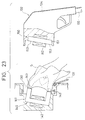
- the joint surfaces 163A, 163B of the secondary core 161 also communicate with the outside via the open portion of the receptacle 130 when the cover 131 is opened as in Embodiment 7 of the present invention (see Fig. 22), extraneous substances sticking to the joint surfaces 163A, 163B are easily found out.
- the cleaning of the joint surface 163A of the cylindrical portion 161A and that of the joint surface 163B of the prism portion 161B may be carried out separately during the cleaning work.
Landscapes
- Engineering & Computer Science (AREA)
- Power Engineering (AREA)
- Transportation (AREA)
- Mechanical Engineering (AREA)
- Computer Networks & Wireless Communication (AREA)
- Electric Propulsion And Braking For Vehicles (AREA)
- Secondary Cells (AREA)
- Details Of Connecting Devices For Male And Female Coupling (AREA)
- Charge And Discharge Circuits For Batteries Or The Like (AREA)
Applications Claiming Priority (7)
| Application Number | Priority Date | Filing Date | Title |
|---|---|---|---|
| JP21166996 | 1996-08-09 | ||
| JP21166996 | 1996-08-09 | ||
| JP2885597A JPH10112903A (ja) | 1996-08-09 | 1997-02-13 | 電気自動車充電用磁気結合装置 |
| JP2885597 | 1997-02-13 | ||
| JP9170702A JPH10112354A (ja) | 1996-08-09 | 1997-06-26 | 電気自動車用充電コネクタ |
| JP17070297 | 1997-06-26 | ||
| EP97113753A EP0823717A3 (de) | 1996-08-09 | 1997-08-08 | Verbinderanordnung zum Laden eines elektrischen Fahrzeugs |
Related Parent Applications (1)
| Application Number | Title | Priority Date | Filing Date |
|---|---|---|---|
| EP97113753.4 Division | 1997-08-08 |
Publications (2)
| Publication Number | Publication Date |
|---|---|
| EP0977215A2 true EP0977215A2 (de) | 2000-02-02 |
| EP0977215A3 EP0977215A3 (de) | 2000-12-06 |
Family
ID=27286341
Family Applications (2)
| Application Number | Title | Priority Date | Filing Date |
|---|---|---|---|
| EP99122516A Withdrawn EP0977215A3 (de) | 1996-08-09 | 1997-08-08 | Verbinderanordnung zum Laden eines elektrischen Fahrzeugs |
| EP97113753A Ceased EP0823717A3 (de) | 1996-08-09 | 1997-08-08 | Verbinderanordnung zum Laden eines elektrischen Fahrzeugs |
Family Applications After (1)
| Application Number | Title | Priority Date | Filing Date |
|---|---|---|---|
| EP97113753A Ceased EP0823717A3 (de) | 1996-08-09 | 1997-08-08 | Verbinderanordnung zum Laden eines elektrischen Fahrzeugs |
Country Status (2)
| Country | Link |
|---|---|
| US (1) | US5909100A (de) |
| EP (2) | EP0977215A3 (de) |
Cited By (4)
| Publication number | Priority date | Publication date | Assignee | Title |
|---|---|---|---|---|
| FR2962696A1 (fr) * | 2010-07-16 | 2012-01-20 | Renault Sa | Charge sans contact d'une batterie de vehicule automobile. |
| WO2011077108A3 (en) * | 2009-12-21 | 2012-01-26 | Hiltech Developments Limited | Vehicle charging apparatus |
| CN106129713A (zh) * | 2016-08-19 | 2016-11-16 | 康泰医学系统(秦皇岛)股份有限公司 | 一种具有防静电及防呆结构的充电通信接口 |
| US20200003958A1 (en) * | 2014-12-14 | 2020-01-02 | Telescent Inc. | High reliability robotic cross-connect systems |
Families Citing this family (104)
| Publication number | Priority date | Publication date | Assignee | Title |
|---|---|---|---|---|
| CA2218919C (en) * | 1995-05-29 | 2004-03-30 | Matsushita Electric Industrial Co., Ltd. | Power supply unit |
| JP3786392B2 (ja) * | 1998-09-09 | 2006-06-14 | 本田技研工業株式会社 | 電動車両用充電装置 |
| JP2001167802A (ja) * | 1999-12-07 | 2001-06-22 | Toyota Autom Loom Works Ltd | 電磁誘導型非接触充電用の給電用カプラの衝撃吸収構造 |
| US6565119B2 (en) | 2001-07-11 | 2003-05-20 | Trw Inc. | Vehicle occupant safety apparatus with restraint communication bus and transformer connections |
| JP2003347138A (ja) * | 2002-05-24 | 2003-12-05 | Yazaki Corp | 電磁誘導型コネクタ |
| US7049822B2 (en) * | 2002-10-31 | 2006-05-23 | Hsn Improvements, Llc | Combination battery, light bulb, and fuse tester |
| US6994560B2 (en) * | 2003-12-19 | 2006-02-07 | Institute For Home Economics Of Japan, Inc. | External power source connecting device for an electric vehicle |
| DE602004025087D1 (de) * | 2004-05-11 | 2010-03-04 | Concens As | Kombination aus einer Energiequelle und einem elektrischen Gerät mit einem Magnethalter |
| GB0422349D0 (en) * | 2004-10-06 | 2004-11-10 | Zi Medical Plc | Electrical recharger unit |
| DE602006008906D1 (de) | 2005-03-14 | 2009-10-15 | Philips Intellectual Property | System, induktive bestromungseinrichtung, bestrombare last und verfahren zur ermöglichung eines drahtlosen stromtransfers |
| US7351066B2 (en) | 2005-09-26 | 2008-04-01 | Apple Computer, Inc. | Electromagnetic connector for electronic device |
| JP4165582B2 (ja) * | 2006-07-14 | 2008-10-15 | 松下電工株式会社 | 電気かみそりと充電器との保持構造 |
| US7741806B2 (en) * | 2006-08-25 | 2010-06-22 | Meridian Design, Inc. | Magnetically attachable battery recharging |
| US7801573B2 (en) * | 2006-12-22 | 2010-09-21 | Vtech Telecommunications Limited | Magnetic holder for rechargeable devices |
| JP4924122B2 (ja) * | 2007-03-16 | 2012-04-25 | 富士ゼロックス株式会社 | 非接触伝送装置 |
| US8307967B2 (en) | 2007-07-04 | 2012-11-13 | Satyajit Patwardhan | Widely deployable charging system for vehicles |
| US8028533B2 (en) * | 2007-11-28 | 2011-10-04 | E & J Enterprises, Llc | Defrost indicator |
| CA2715918A1 (en) | 2008-02-22 | 2009-08-27 | Access Business Group International Llc | Magnetic positioning for inductive coupling |
| US8288986B2 (en) | 2008-04-28 | 2012-10-16 | Aerovironment Inc. | Concentric connector for electric vehicles |
| US20090277931A1 (en) | 2008-05-08 | 2009-11-12 | Achim Philipp Zapp | Wireless spout and system for free-and pre-measured dispensing |
| CN101732059A (zh) * | 2008-11-21 | 2010-06-16 | Ge医疗系统环球技术有限公司 | 一种ct扫描设备 |
| DE102009007359A1 (de) * | 2009-02-04 | 2010-08-05 | Zweibrüder Optoelectronics GmbH | Ladestation |
| US20100201309A1 (en) * | 2009-02-10 | 2010-08-12 | Meek Ivan C | Systems and methods for coupling a vehicle to an external grid and/or network |
| JP5234176B2 (ja) | 2009-04-23 | 2013-07-10 | トヨタ自動車株式会社 | 車両、充電ケーブルおよび車両の充電システム |
| DE102009022886A1 (de) | 2009-05-27 | 2010-12-02 | Bayerische Motoren Werke Aktiengesellschaft | Vorrichtung zur mechanischen und elektrischen Anbindung eines tragbaren, batteriebetriebenen Geräts und tragbares, batteriebetriebenes Gerät |
| DE102009023409B4 (de) * | 2009-05-29 | 2024-10-31 | Rohde & Schwarz GmbH & Co. Kommanditgesellschaft | System zur elektrischen Energieübertragung |
| WO2011030256A2 (en) * | 2009-09-09 | 2011-03-17 | Koninklijke Philips Electronics N.V. | An electronic device as well as a base part and an electronic element suitable for use in such an electronic device |
| US8269454B2 (en) * | 2009-10-09 | 2012-09-18 | Tai-Her Yang | Power charging device with charge saturation disconnector through electromagnetic force release |
| US8862288B2 (en) | 2010-05-18 | 2014-10-14 | The Boeing Company | Vehicle base station |
| US8899903B1 (en) | 2010-05-18 | 2014-12-02 | The Boeing Company | Vehicle base station |
| US8841881B2 (en) | 2010-06-02 | 2014-09-23 | Bryan Marc Failing | Energy transfer with vehicles |
| DE102010027670B4 (de) * | 2010-07-20 | 2018-10-11 | Siemens Aktiengesellschaft | Vorrichtung und Verfahren zum Anschließen eines elektrischen Energiespeichers an eine Ladestation |
| JP5842181B2 (ja) * | 2010-10-20 | 2016-01-13 | パナソニックIpマネジメント株式会社 | 電気自動車充電装置 |
| US20120126747A1 (en) * | 2010-11-19 | 2012-05-24 | Delphi Technologies, Inc. | Battery charger having non-contact electrical switch |
| WO2012066146A1 (de) * | 2010-11-19 | 2012-05-24 | Fidlock Gmbh | Verschlussvorrichtung mit elektromagnetischer kopplung |
| EP2469663B1 (de) * | 2010-12-24 | 2020-06-17 | Phitek Systems Limited | Magnetisches Verbindungssystem |
| US8627534B2 (en) * | 2011-04-20 | 2014-01-14 | Tesla Motors, Inc. | Cleaning feature for electric charging connector |
| KR101103028B1 (ko) * | 2011-04-27 | 2012-01-05 | 오토커넥터주식회사 | 전자기 전기 접속 장치의 개량구조 |
| DE102011077427B4 (de) | 2011-06-10 | 2026-01-15 | Bayerische Motoren Werke Aktiengesellschaft | Ladevorrichtung und Ladeverfahren mit schwimmender Ladeeinheit |
| US8853998B2 (en) * | 2011-06-30 | 2014-10-07 | Blackberry Limited | Portable electronic device dock having a connector movable in response to a magnetic force |
| US10361752B2 (en) | 2011-08-12 | 2019-07-23 | Koninklijke Philips N.V. | Universal voltage converter and inductive power coupling |
| US8907752B2 (en) | 2011-09-12 | 2014-12-09 | Justin Richard Wodrich | Integrated inductive charging in protective cover |
| KR101875942B1 (ko) * | 2011-10-18 | 2018-07-06 | 엘지이노텍 주식회사 | 무선전력 수신장치 및 무선전력 전송 시스템 |
| US9352652B2 (en) * | 2012-06-29 | 2016-05-31 | Schneider Electric USA, Inc. | Coupler for electric vehicle charging station |
| DE102012212254B3 (de) * | 2012-07-12 | 2014-01-09 | Fraunhofer-Gesellschaft zur Förderung der angewandten Forschung e.V. | Verbinder zur leitungsungebundenen Signalübertragung |
| US9281701B2 (en) * | 2012-11-16 | 2016-03-08 | Ati Technologies Ulc | Wireless power transfer device for charging mobile/portable devices |
| KR101449197B1 (ko) * | 2012-12-26 | 2014-10-08 | 현대자동차주식회사 | 전기자동차 충전용 자성커넥터 장치 |
| US9142912B1 (en) * | 2013-03-14 | 2015-09-22 | Lon W. Allen | Magnetic coupling systems |
| US9597968B2 (en) * | 2013-08-08 | 2017-03-21 | GM Global Technology Operations LLC | Shroud for electric vehicle charger receptacle |
| DE102013218471A1 (de) * | 2013-09-16 | 2015-03-19 | Robert Bosch Gmbh | Ladevorrichtung, Empfangsvorrichtung, System und Verfahren zum induktiven Laden eines Akkumulators |
| CN105813804A (zh) * | 2013-10-11 | 2016-07-27 | 奥利欧装置公司 | 无线电子设备和使用方法 |
| CN203589349U (zh) * | 2013-10-12 | 2014-05-07 | 富士康(昆山)电脑接插件有限公司 | 电连接器 |
| JP2015146705A (ja) * | 2014-02-04 | 2015-08-13 | タイコエレクトロニクスジャパン合同会社 | 無接点充電装置 |
| US9859727B2 (en) * | 2014-06-25 | 2018-01-02 | Adonit Co., Ltd. | Battery charger device and method |
| US9531118B2 (en) | 2014-07-10 | 2016-12-27 | Norman R. Byrne | Electrical power coupling with magnetic connections |
| US20160072337A1 (en) * | 2014-09-04 | 2016-03-10 | Samsung Electro-Mechanics Co., Ltd. | Case and apparatus including the same |
| US9613739B2 (en) * | 2014-12-23 | 2017-04-04 | Qualcomm Incorporated | Electromagnetic mating interface |
| KR20170085900A (ko) * | 2016-01-15 | 2017-07-25 | 엘지이노텍 주식회사 | 무선 전력 전송 시스템에서 무선 전력 송신기 및 수신기 |
| CA2957527C (en) | 2016-02-12 | 2022-04-19 | Norman R. Byrne | Electrical power load switch with connection sensor |
| AT518327B1 (de) | 2016-03-25 | 2017-12-15 | Ing Hermann Stockinger Dipl | Kontaktierungssystem zum Herstellen einer elektrischen Verbindung zwischen einem primären Gerät und einem sekundären Gerät |
| US20170297437A1 (en) * | 2016-04-19 | 2017-10-19 | Faraday&Future Inc. | Charging connection for an electric vehicle |
| MX366612B (es) | 2016-05-02 | 2019-07-15 | Norman R Byrne | Conector electrico de cierre por torsion. |
| FR3052602B1 (fr) * | 2016-06-13 | 2020-09-18 | Gulplug | Systeme de connexion electrique |
| BR102017021521A2 (pt) | 2016-10-07 | 2018-06-12 | Norman R. Byrne | Cabo de alimentação elétrica, e método de energização e desenergização seletiva de uma extremidade de saída de energia |
| CN106356953B (zh) * | 2016-10-26 | 2018-11-09 | 黑龙江省电力科学研究院 | 一种巡检机器人无线充电装置 |
| CN106627893A (zh) * | 2016-12-07 | 2017-05-10 | 广东技术师范学院 | 平衡车及轮式车辆 |
| US11491884B2 (en) | 2017-01-19 | 2022-11-08 | Curtis Instruments Inc. | Magnetic charger connector for wheelchair |
| US10686336B2 (en) | 2017-05-30 | 2020-06-16 | Wireless Advanced Vehicle Electrification, Inc. | Single feed multi-pad wireless charging |
| DE102017212149A1 (de) * | 2017-07-14 | 2019-01-17 | Fidlock Gmbh | Verschlussvorrichtung mit elektrischem Kontakt |
| CN107244262A (zh) * | 2017-07-27 | 2017-10-13 | 杭州力谱科技有限公司 | 一种充电桩 |
| JP2021507475A (ja) * | 2017-12-21 | 2021-02-22 | アイディール インダストリーズ,インク. | 転換力ラッチングシステム |
| US11462943B2 (en) | 2018-01-30 | 2022-10-04 | Wireless Advanced Vehicle Electrification, Llc | DC link charging of capacitor in a wireless power transfer pad |
| EP3750226B1 (de) * | 2018-02-05 | 2022-08-10 | McColl, Stuart Frazer | Verfahren und system zur magnetischen verriegelung eines ladeanschlusses an einem elektrofahrzeug |
| US10759296B2 (en) * | 2018-07-19 | 2020-09-01 | Chih-Yuan Chang | Charging apparatus for electric vehicle |
| US10566734B1 (en) | 2018-08-02 | 2020-02-18 | Roboteq, Inc | System for facilitating electrical connection of a first electrical unit comprised in a first object with a second electrical unit comprised in a second object |
| US11424561B2 (en) | 2019-07-03 | 2022-08-23 | Norman R. Byrne | Outlet-level electrical energy management system |
| DE102019123967A1 (de) * | 2019-09-06 | 2021-03-11 | Volkswagen Aktiengesellschaft | Batteriesystem für ein Kraftfahrzeug und Kraftfahrzeug mit austauschbarer Batterie |
| US11710988B2 (en) | 2019-09-27 | 2023-07-25 | Apple Inc. | Magnetic alignment systems with NFC for electronic devices |
| KR20220041894A (ko) | 2019-09-27 | 2022-04-01 | 애플 인크. | 전자 디바이스를 위한 자기 정렬 시스템 |
| CN110676654B (zh) * | 2019-10-14 | 2021-07-06 | 江苏卡威汽车工业集团股份有限公司 | 一种新能源汽车用电池防松接线装置 |
| US11485242B2 (en) * | 2019-11-13 | 2022-11-01 | Ford Global Technologies, Llc | Vehicle charging system |
| CA3158048C (en) * | 2019-11-15 | 2023-06-20 | Ryan D. Aberle | Magnetic tether switch |
| CN116210064A (zh) * | 2020-06-07 | 2023-06-02 | 莫比健康(股份)责任有限公司 | 用于稳定和阻挡且具可控和可调节变形的屈服机构的静态wpt耦合装置 |
| US12040643B2 (en) | 2020-08-05 | 2024-07-16 | Apple Inc. | Magnetically attachable charging devices |
| US12300837B2 (en) | 2020-08-05 | 2025-05-13 | Apple Inc. | Magnetically attachable battery pack |
| US11867352B2 (en) | 2020-08-05 | 2024-01-09 | Apple Inc. | Adapter for charging and stabilizing cameras |
| US11839279B2 (en) | 2020-09-22 | 2023-12-12 | Apple Inc. | Magnetically attachable wallet |
| US12597803B2 (en) | 2020-09-23 | 2026-04-07 | Apple Inc. | Foldable and rigid docking stations for charging multiple devices |
| JP7317085B2 (ja) | 2020-09-23 | 2023-07-28 | アップル インコーポレイテッド | 複数のデバイスを充電するための折り畳み可能剛性ドッキングステーション |
| US12081035B2 (en) | 2020-09-23 | 2024-09-03 | Apple Inc. | Docking stations with hinged charging puck |
| US11424573B2 (en) * | 2020-09-24 | 2022-08-23 | Apple Inc. | Magnetic connectors with self-centering floating contacts |
| US12465846B2 (en) | 2020-09-25 | 2025-11-11 | Apple Inc. | Magnetically attachable gaming accessory |
| US11942722B2 (en) * | 2020-09-25 | 2024-03-26 | Apple Inc. | Magnetic circuit for magnetic connector |
| US11904715B2 (en) * | 2020-11-12 | 2024-02-20 | Rivian Ip Holdings, Llc | Automated plug-in system and method |
| KR102790199B1 (ko) * | 2021-01-05 | 2025-04-03 | 주식회사 엘지에너지솔루션 | 연결 구조 |
| US20220297798A1 (en) * | 2021-03-16 | 2022-09-22 | Tien Hsin Industries Co., Ltd. | Electronic derailleur |
| CN113161809A (zh) * | 2021-04-21 | 2021-07-23 | 安徽声讯信息技术有限公司 | 一种便于连接的充电接口 |
| US12476497B2 (en) * | 2021-06-23 | 2025-11-18 | Apple Inc. | Wireless power systems with magnetic alignment systems |
| US11757229B2 (en) * | 2021-11-11 | 2023-09-12 | Onanon, Inc. | Electromagnetic Electrical Connector System |
| KR102447722B1 (ko) * | 2022-01-20 | 2022-09-27 | 주식회사 센서뷰 | Rf 동축 케이블용 플러그 및 어댑터와 이를 구비하는 rf 커넥터 조립체 |
| US12555950B1 (en) * | 2022-03-08 | 2026-02-17 | Cinch Connectivity Solutions Inc. | Electrical connector with a shell |
| US12093075B2 (en) | 2022-09-08 | 2024-09-17 | Apple Inc. | Magnetic attachment system for input device |
| TWM643061U (zh) * | 2023-03-30 | 2023-06-21 | 帥群微電子股份有限公司 | 無線充電系統及其自主移動載具 |
| DE102023122479A1 (de) * | 2023-08-22 | 2025-02-27 | Bayerische Motoren Werke Aktiengesellschaft | Ladesteckeranordnung für ein zumindest teilweise elektrisch betriebenes Kraftfahrzeug |
Family Cites Families (10)
| Publication number | Priority date | Publication date | Assignee | Title |
|---|---|---|---|---|
| GB1501502A (en) * | 1975-01-08 | 1978-02-15 | Pelcon Ltd | Inductive connectors |
| JPS61214407A (ja) * | 1985-03-19 | 1986-09-24 | Mita Ind Co Ltd | 相対回転部間の電力伝達装置 |
| US4912735A (en) * | 1988-07-18 | 1990-03-27 | Elscint Ltd. | Power transfer apparatus particularly for CT scanner |
| EP0552737A1 (de) * | 1992-01-22 | 1993-07-28 | Hughes Aircraft Company | Wetterfester längsseitiger Lader |
| FR2695266B1 (fr) * | 1992-09-02 | 1994-09-30 | Cableco Sa | Ensemble pour recharger les batteries d'accumulateurs d'un véhicule automobile électrique. |
| JPH06178465A (ja) * | 1992-12-11 | 1994-06-24 | Toyota Autom Loom Works Ltd | 電磁給電装置 |
| US5412304A (en) * | 1993-08-09 | 1995-05-02 | Hughes Aircraft Company | Cooled primary of automobile battery charging transformer |
| US5408209A (en) * | 1993-11-02 | 1995-04-18 | Hughes Aircraft Company | Cooled secondary coils of electric automobile charging transformer |
| JPH089512A (ja) * | 1994-06-23 | 1996-01-12 | Toyota Autom Loom Works Ltd | 電動車用電磁給電装置 |
| US5703461A (en) * | 1995-06-28 | 1997-12-30 | Kabushiki Kaisha Toyoda Jidoshokki Seisakusho | Inductive coupler for electric vehicle charger |
-
1997
- 1997-08-08 EP EP99122516A patent/EP0977215A3/de not_active Withdrawn
- 1997-08-08 EP EP97113753A patent/EP0823717A3/de not_active Ceased
- 1997-08-08 US US08/908,620 patent/US5909100A/en not_active Expired - Fee Related
Cited By (10)
| Publication number | Priority date | Publication date | Assignee | Title |
|---|---|---|---|---|
| WO2011077108A3 (en) * | 2009-12-21 | 2012-01-26 | Hiltech Developments Limited | Vehicle charging apparatus |
| FR2962696A1 (fr) * | 2010-07-16 | 2012-01-20 | Renault Sa | Charge sans contact d'une batterie de vehicule automobile. |
| WO2012007666A3 (fr) * | 2010-07-16 | 2012-03-22 | Renault S.A.S. | Charge sans contact d'une batterie de vehicule automobile |
| US20200003958A1 (en) * | 2014-12-14 | 2020-01-02 | Telescent Inc. | High reliability robotic cross-connect systems |
| US10649149B2 (en) * | 2014-12-14 | 2020-05-12 | Telescent Inc. | High reliability robotic cross-connect systems |
| US11340402B2 (en) | 2014-12-14 | 2022-05-24 | Telescent Inc. | High reliability robotic cross-connect systems |
| US11953731B2 (en) | 2014-12-14 | 2024-04-09 | Telescent Inc. | High reliability robotic cross-connect systems |
| US12386120B2 (en) | 2014-12-14 | 2025-08-12 | Telescent Inc. | High-reliability robotic cross-connect systems |
| CN106129713A (zh) * | 2016-08-19 | 2016-11-16 | 康泰医学系统(秦皇岛)股份有限公司 | 一种具有防静电及防呆结构的充电通信接口 |
| CN106129713B (zh) * | 2016-08-19 | 2019-03-19 | 康泰医学系统(秦皇岛)股份有限公司 | 一种具有防静电及防呆结构的充电通信接口 |
Also Published As
| Publication number | Publication date |
|---|---|
| EP0823717A3 (de) | 1998-04-08 |
| EP0823717A2 (de) | 1998-02-11 |
| US5909100A (en) | 1999-06-01 |
| EP0977215A3 (de) | 2000-12-06 |
Similar Documents
| Publication | Publication Date | Title |
|---|---|---|
| US5909100A (en) | Charging connector for electric vehicle | |
| JPH10112354A (ja) | 電気自動車用充電コネクタ | |
| JPH0219187A (ja) | 電気器具用装置 | |
| US8027497B2 (en) | Hearing device with rechargeable battery and movably mounted charging contacts | |
| JP2581640B2 (ja) | 壁または天井に設置される誘電型充電装置 | |
| JP3424568B2 (ja) | 電池ケース保持機構およびそれを搭載した電動車両 | |
| EP3729480B1 (de) | Verriegelungssystem mit konvertierbarer kraft | |
| JP2004206973A (ja) | マグネット式コンセントアダプタ | |
| JPS60216479A (ja) | コネクタ装置 | |
| CN218772663U (zh) | 遥控器 | |
| JPH05342979A (ja) | 暗電流用ヒューズ機構 | |
| CN114929510A (zh) | 用于将车辆的电插座连接到连接器的方法 | |
| JPH1127868A (ja) | 電気自動車充電用コネクタ | |
| JP2009165239A (ja) | 充電台 | |
| JP2002110310A (ja) | 端子挿入装置及び端子挿入方法 | |
| CN115917103A (zh) | 磁性锁定-释放机构 | |
| JPH10112903A (ja) | 電気自動車充電用磁気結合装置 | |
| CN222963620U (zh) | 一种快拆连接组件及手持云台 | |
| CN218241712U (zh) | 一种便于更换的磁保持继电器 | |
| US20240367534A1 (en) | Electric vehicle charging system with magnetic plug system | |
| CN223339413U (zh) | 收纳盒以及工具组件 | |
| CN219639838U (zh) | 电子终端设备固定装置 | |
| CN223956522U (zh) | 一种继电器 | |
| CN210120089U (zh) | 一种可断开闭合电路的电表连接结构及包含其的电能表 | |
| JP2003197065A (ja) | スイッチ装置 |
Legal Events
| Date | Code | Title | Description |
|---|---|---|---|
| PUAI | Public reference made under article 153(3) epc to a published international application that has entered the european phase |
Free format text: ORIGINAL CODE: 0009012 |
|
| 17P | Request for examination filed |
Effective date: 19991111 |
|
| AC | Divisional application: reference to earlier application |
Ref document number: 823717 Country of ref document: EP |
|
| AK | Designated contracting states |
Kind code of ref document: A2 Designated state(s): DE FR GB IT |
|
| AX | Request for extension of the european patent |
Free format text: AL;LT;LV;RO;SI |
|
| PUAL | Search report despatched |
Free format text: ORIGINAL CODE: 0009013 |
|
| AK | Designated contracting states |
Kind code of ref document: A3 Designated state(s): DE FR GB IT |
|
| AX | Request for extension of the european patent |
Free format text: AL;LT;LV;RO;SI |
|
| AKX | Designation fees paid |
Free format text: DE FR GB IT |
|
| STAA | Information on the status of an ep patent application or granted ep patent |
Free format text: STATUS: THE APPLICATION IS DEEMED TO BE WITHDRAWN |
|
| 18D | Application deemed to be withdrawn |
Effective date: 20010301 |