EP0977306A2 - Mehrstrahl-phasengesteuerte Antenne und damit verbundenes Verfahren - Google Patents
Mehrstrahl-phasengesteuerte Antenne und damit verbundenes Verfahren Download PDFInfo
- Publication number
- EP0977306A2 EP0977306A2 EP99108661A EP99108661A EP0977306A2 EP 0977306 A2 EP0977306 A2 EP 0977306A2 EP 99108661 A EP99108661 A EP 99108661A EP 99108661 A EP99108661 A EP 99108661A EP 0977306 A2 EP0977306 A2 EP 0977306A2
- Authority
- EP
- European Patent Office
- Prior art keywords
- signal
- scanning
- manifold
- antenna
- photonic
- Prior art date
- Legal status (The legal status is an assumption and is not a legal conclusion. Google has not performed a legal analysis and makes no representation as to the accuracy of the status listed.)
- Granted
Links
- 238000000034 method Methods 0.000 title claims description 14
- 230000003287 optical effect Effects 0.000 claims abstract description 53
- 239000013307 optical fiber Substances 0.000 claims description 15
- 230000010363 phase shift Effects 0.000 claims description 11
- 238000001914 filtration Methods 0.000 claims description 3
- 230000008859 change Effects 0.000 abstract description 5
- 230000005855 radiation Effects 0.000 abstract description 5
- 238000010586 diagram Methods 0.000 description 19
- 239000000835 fiber Substances 0.000 description 16
- 230000001427 coherent effect Effects 0.000 description 10
- 230000008569 process Effects 0.000 description 5
- 208000004350 Strabismus Diseases 0.000 description 4
- 230000000750 progressive effect Effects 0.000 description 4
- 230000004044 response Effects 0.000 description 4
- 238000003491 array Methods 0.000 description 2
- 238000013461 design Methods 0.000 description 2
- 238000004519 manufacturing process Methods 0.000 description 2
- 238000012545 processing Methods 0.000 description 2
- 239000007787 solid Substances 0.000 description 2
- 238000012546 transfer Methods 0.000 description 2
- 206010000269 abscess Diseases 0.000 description 1
- 230000005540 biological transmission Effects 0.000 description 1
- 239000000969 carrier Substances 0.000 description 1
- 230000008878 coupling Effects 0.000 description 1
- 238000010168 coupling process Methods 0.000 description 1
- 238000005859 coupling reaction Methods 0.000 description 1
- 230000003247 decreasing effect Effects 0.000 description 1
- 230000000694 effects Effects 0.000 description 1
- 238000003780 insertion Methods 0.000 description 1
- 230000037431 insertion Effects 0.000 description 1
- 238000007689 inspection Methods 0.000 description 1
- 238000012986 modification Methods 0.000 description 1
- 230000004048 modification Effects 0.000 description 1
- 230000008707 rearrangement Effects 0.000 description 1
- 230000009467 reduction Effects 0.000 description 1
- 238000001228 spectrum Methods 0.000 description 1
- 238000013519 translation Methods 0.000 description 1
Images



Classifications
-
- H—ELECTRICITY
- H01—ELECTRIC ELEMENTS
- H01Q—ANTENNAS, i.e. RADIO AERIALS
- H01Q3/00—Arrangements for changing or varying the orientation or the shape of the directional pattern of the waves radiated from an antenna or antenna system
- H01Q3/26—Arrangements for changing or varying the orientation or the shape of the directional pattern of the waves radiated from an antenna or antenna system varying the relative phase or relative amplitude of energisation between two or more active radiating elements; varying the distribution of energy across a radiating aperture
- H01Q3/2676—Optically controlled phased array
-
- H—ELECTRICITY
- H01—ELECTRIC ELEMENTS
- H01Q—ANTENNAS, i.e. RADIO AERIALS
- H01Q25/00—Antennas or antenna systems providing at least two radiating patterns
Definitions
- the present invention relates generally to antennas and more particularly to phased array antennas.
- the antenna beam of a phased array antenna points in a direction that is normal to its phase front.
- a plurality of phase shifters are incorporated in the array so that the phase front can be steered as desired.
- beam-steering phase shifts are realized by varying the frequency of signals that are transmitted through time delay elements. This latter process scans the antenna beam but typically has the disadvantage that the frequency of the radiated beam is dependant upon the beam's pointing direction.
- U.S. Patent 3,090,928 (issued May 21, 1963 in the name of William R. Welty) described the use of two time delay elements (e.g., tapped delay lines) to realize beam steering with a constant radiated frequency.
- a reference signal is sent down one delay line and a tuning signal is sent down the other delay line.
- Corresponding tap points on the delay lines are coupled to mixers and the mixer outputs are coupled through filters to array radiators.
- the filters are configured to pass a desired mixing product (e.g., a difference signal) and block the reference and tuning signals.
- U.S. Patent application Serial No. 08/711,428 (entitled “Simultaneous Multibeam and Frequency Active Photonic Array Radar Apparatus” and filed September 5, 1996) is directed to active array systems chat process multiple beams over a wide frequency range. It replaces conventional electronic radio-frequency (RF) delay lines (e.g., those of U.S. Patent 3.090.928) with fiber optic delay lines.
- the delay lines provide a wide operating frequency range and the ability to process different RF signals through the use of light signals that have different wavelengths. Accordingly, an RF signal that is modulated on one light carrier does not interact with another RF signal that is modulated on a second light carrier.
- the RF signals may be placed on and taken out of the fiber delay lines using optical filtering (e.g., wavelength division multiplexing) of different light carriers.
- a basic transmit manifold which has RF oscillators that generate a tuning frequency and a signal frequency.
- the transmit manifold also includes a solid state light source and electro-optic modulators that are coupled to an input of an optical manifold which is formed by a plurality of optical fibers.
- the output of this optical manifold is connected through photodiode detectors to array radiators of which each includes a series combination of a mixer, a filter and an RF amplifier.
- a transmit implementation is shown that can provide two transmitted beams. With the exception of the optical manifold, this implementation duplicates all of the above-recited structures. In addition, pairs of wavelength division multiplexing (WDM) devices interface the optical manifold to the other structures. Accordingly, an active array system with multiple radiated beams can be realized but only at the expense of multiple duplications of photonic and electronic modules. It is stated that this duplication minimizes unwanted mixing products. However, this duplication also causes significant increases in size, weight and cost of the active array system.
- WDM wavelength division multiplexing
- the present invention is directed to multibeam phased array antennas that require significantly less antenna structures and elements than conventional antennas.
- the signal generator supplies m signal pairs that each include a respective frequency-swept scanning signal s s and a respective reference signal s r whose frequency is a selected one of the sum and the difference of the frequencies of the scanning signal s s and a respective operating signal s o .
- the first photonic manifold forms n optical paths whose lengths progressively increase by a selected path length ⁇ L and the second photonic manifold forms n equal-length optical paths.
- the first signal combiner combines all scanning signals s s and delivers them to the first photonic manifold.
- the second signal combiner combines all reference signals s r and delivers them to the second photonic manifold.
- Each of n radiative modules includes a mixer, a filter and a radiator.
- Each mixer receives scanning signals and reference signals from the photonic manifolds and forms a set of mixed signals.
- Each filter recovers a phase-shifted version of the respective operating signal s o of each signal pair.
- Each radiator then radiates the phase-shifted versions to form m radiated beams.
- Methods of the invention avoid the generation of spurious radiated signals so that all signal pairs can be mixed and filtered in common mixers and filters of each radiative module.
- all scanning signals are carried by a common light carrier signal and all reference signals are carried by another common light carrier signal.
- the methods include the step of selecting the scanning signals of the signal pairs to each have a different integer number of 2 ⁇ phase shifts over the path length ⁇ L.
- the integer numbers are chosen so that scanning signals and reference signals of different signal pairs form mixing products that can be rejected by the filters of each radiative module.
- antenna embodiments translate the photonic manifolds to lower intermediate frequencies to enhance the availability and lower the cost of components, reduce the precision required in cutting of optical fibers and realize a standard module that can be used in forming various multibeam phased array antennas.
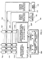
- FIG. 1 illustrates a multibeam phased array antenna 20 which generates two independently-controlled antenna beams 22 and 24.
- the antenna includes an electronic signal generator 26 and a plurality of radiative modules 28A-28N. These antenna elements are coupled together by first and second photonic manifolds 30 and 32. An operational description of the antenna 20 is enhanced by preceding it with the following detailed description of antenna elements.
- the electronic signal generator 26 has two phase coherent sources 34 and 35 that each generate a signal pair.
- Each signal pair comprises a frequency-swept scanning signal s s and a reference signal s r whose frequency is either the sum or the difference of the frequencies of the scanning signal s s and a fixed-frequency operating signal s o .
- the first coherent source 34 generates signals s s1 and s r1
- the second coherent source 35 generates signals s s2 and s r2 .
- the reference signals s r1 and s r2 are coupled through a first combiner 36 to the first photonic manifold 30.
- the scanning signals s s1 and s s2 are coupled through a second combiner 37 to the second photonic manifold 32.
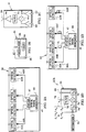
- FIG. 2A shows that the first photonic manifold 30 has a plurality of optical detectors 42A-42N and a modulated optical signal generator 44 which has a modulation input port 45.
- the detectors 42 and the generator 44 are coupled together by an optical splitter 47 and a plurality of equal-length optical paths. In the antenna 20, these paths are realized with optical waveguides in the form of optical fibers 48A-48N.
- FIG. 2B shows that the second photonic manifold 32 also has a plurality of optical detectors 42 and an optical signal generator 44 but they are coupled together by an optical splitter 47 and progressive-length optical paths that are realized with optical waveguides in the form of optical fibers 50A-50N.
- the lengths of the optical fibers 50 progressively change by a selected length ⁇ L (e.g., fiber 50B is longer than fiber 50A by ⁇ L, fiber 50C is longer than fiber 50B by ⁇ L and so on). Accordingly, the phase slopes (in response to the swept-frequency scanning signal s s ) of the fibers 50 progressively change by a selected slope increment.
- each radiative module 28 includes a filter 54 that is coupled between a mixer 55 and a radiator 56 (e.g., a horn, a slot or a flared notch).
- the output of the mixer is preferably amplified by a transmit amplifier 58 and the inputs 60 and 62 of the module are preferably amplified by buffer amplifiers 64.
- the input 60 of each radiative module 28A-28N is coupled to a respective one of the equal-length optical fibers 48A-48 of the photonic manifold 30 and the input 62 is coupled to a respective one of the progressive-length optical fibers 50A-50N of the photonic manifold 32. These connections are symbolized by indicated overlaps of the antenna elements 28A-28N, 30 and 32.
- the optical detectors 42A-42N may actually reside in respective ones of the radiative modules 28A-28N.
- the phase coherent sources 34 and 35 can be formed by various structures that can generate the coherent signals s r and s s .
- An exemplary structure 70 is shown in FIG. 2D to have a mixer 72 coupled between signal generators 74 and 75 that respectively generate the fixed-frequency operating signal s o and the swept-frequency scanning signal s s .
- a filter 76 connects the mixer to an output port 78. The filter is configured to pass a selected one of the sum and difference of the operating signal s o and the scanning signal s s .
- This passed signal is the reference signal s r and it is available at the output port 78.
- the scanning signal s s is made available at another output port 80.
- the output ports 78 and 80 are respectively connected to the combiners 36 and 37.
- Information e.g., analog or digital data applied by amplitude, phase or frequency modulation
- the optical signal generators 44 of FIGS. 2A and 2B can be any of a variety of modulatable generators.
- the generators are directly modulated diode lasers.
- the generators are each a laser 84 that is connected through a modulator 86 (e.g., a Mach-Zehnder electro-optic modulator) to an output port 87 as shown in FIG. 2E.
- a modulator 86 e.g., a Mach-Zehnder electro-optic modulator
- the radiative modules 28A-28N are configured to radiate the operating signal s o that is associated with the phase coherent sources 34 and 35.
- the filter 76 of the phase coherent source 70 of FIG. 2D is configured to pass a reference signal s r that is the sum of the operating signal s o and the scanning signal s s
- the filter 54 of the radiative module 28 of FIG. 2C is configured to pass the difference of the reference signal s r and the scanning signal s s (i.e., the operating signal s o ).
- the filter 76 is configured to pass a reference signal s r that is the difference of the operating signal s o and the scanning signal s s
- the filter 54 is configured to pass the sum of the reference signal s r and the scanning signal s s (i.e., the operating signal s o ).
- the frequency of each reference signal will scan oppositely from the frequency of its respective scanning signal and the frequency of the associated operating signal will be constant.
- the photonic manifold 32 imposes a progressive phase shift on the scanning signals of the radiative modules 28A-28N.
- the radiated operating signals s o also have a progressive phase shift which generates a linear phase front in the radiated signals.
- the optical fibers 50A-50N have a progressive length change of ⁇ L, the progressive phase shift increases with increasing frequency of the scanning signal.
- changing the frequency of the scanning signal s s1 changes the slope of the phase front 82 of radiated antenna beam 22 and changing the frequency of the scanning signal s s2 changes the slope of the phase front 83 of radiated antenna beam 24.
- the beams 22 and 24 can be independently scanned.
- Space at the face of phased array antennas is typically quite limited.
- the spacing of the radiative modules 28A-28N in FIG. 1 must not exceed ⁇ o /2 wherein ⁇ o is the wavelength of the operating signal s o .
- the arrangement of the antenna 20 permits all structures but the optical detectors 42A-42N of FIG. 2A to be spaced away from the array of radiative modules 28A-28N.
- FIGS. 1-2E the antenna teachings of the invention are illustrated in FIGS. 1-2E with reference to simultaneous generation of two antenna beams 82 and 83, the teachings apply in general to the generation of n antenna beams.
- generation of n signal pairs (each pair being a reference signal s r and its corresponding scanning signals s s ) requires two combiners and n phase coherent sources. In an important feature of the invention, however, no other additional antenna structure need be added to that required for generation of a single antenna beam.
- each signal pair generates one of n antenna beams and all signal pairs are carried by one equal-length photonic manifold and one progressive-length photonic manifold.
- all signs pairs are mixed and filtered in a single mixer and filter before being applied to an array radiator.
- antennas of the invention can be realized with a substantial savings in parts, assembly time and cost.
- FIG. 3 illustrates another phased array antenna 100 in which portions are similar to the antenna 20 of FIG. 1 with like elements indicated by like reference numbers.
- the antenna 100 has a local oscillator 102 and a third photonic manifold 104.
- each radiative module 28 of FIG. 1 has been partitioned between a mixer module 106 and an upconverter module 108 as shown respectively in FIGS. 4A and 4B.
- the mixer module 106 is the same as the radiative module 28 except that its power amplifier 58 and radiator 56 have been removed and repositioned at the output of the upconverter module 108. In their place the mixer module 106 has an amplifier 107 and an output port 109.
- the upconverter module also arranges an input port 110, a mixer 111 and a filter 112 in series with the radiator 56.
- An amplifier 114 connects an upconverter port 116 to the mixer 111.
- output ports 109 of mixer modules 106A-106N are connected to input ports 110 of respective ones of upconverter modules 108A-108N. Basically, the antenna 100 adds a signal upconverter between the mixer 55 and radiator 56 of the radiative module 28 of FIG. 2C.
- the third photonic manifold 104 is substantially the same as the first photonic manifold, i.e., it has equal-length optical fibers connecting a plurality of optical detectors to an optical signal generator.
- the optical detectors of this module are closely associated with the upconverter modules 108A-108N as indicated in FIG. 3 by the overlap between these modules and the third photonic manifold 104.
- the operation of the antenna 100 is similar to that of the antenna 20 but, in addition, the equal-length manifold 104 couples upconverter signals from the local oscillator 102 to upconverter modules 108A-108N. Because of the equal-length optical paths of the third photonic manifold 104, these upconverter signals are in-phase and the phase fronts 82 and 83 of FIG. 1 are not disturbed.
- the upconverter signals permit the antenna 100 to radiate multiple microwave beams in a desired microwave frequency (e.g., X-band) while translating the operational frequency of the first and second photonic manifolds 30 and 32 and the electronic signal generator 26 downward to a lower frequency (e.g., 2.5-3 GHz).
- a desired microwave frequency e.g., X-band
- the operational frequency of the first and second photonic manifolds 30 and 32 and the electronic signal generator 26 downward to a lower frequency (e.g., 2.5-3 GHz).
- a lower frequency e.g., 2.5-3 GHz.
- the photonic manifolds 30 and 32 and the electronic signal generator 26 of FIG. 1 have been renumbered as 30IF, 32IF and 26IF to indicate they operate at intermediate frequencies which are translated downward from corresponding frequencies in the antenna 20 of FIG. 1.
- a lower operating frequency also eases fabrication difficulties because it lessens the precision needed in cutting the optical fibers 48A-48N and 50A-50N of the manifolds 30 and 32. Accordingly, the structure of the antenna 100 significantly enhances its producibility.
- FIG. 5 illustrates another phased array antenna 120 in which portions are similar to the antenna 20 of FIG. 1 with like elements indicated by like reference numbers.
- the antenna 120 has a fourth photonic manifold 122 and the upconverter module 108 of FIG. 3 has been partitioned between an upconverter module 124 and a downconverter module 126 as shown in FIGS. 6B and 6C.
- the fourth photonic manifold 122 of FIG. 6A has a plurality of optical generators 128A-128N with modulation inputs 129A-129N (e.g., directly modulated diode lasers) that are each coupled through equal-length optical fibers 130 to a respective one of a plurality of optical detectors 132A-132N.
- a beam summer 140 receives inputs through amplifiers 142 from the optical detectors 132A-132N.
- the upconverter 124 of FIG. 6B is the same as the upconverter 108 of FIG. 4A except that the radiator 56 has been replaced by an output port 144 and the radiator has been moved to the output of the downconverter module 126 of FIG. 6C.
- the latter module has a low-noise amplifier 146 and a mixer 148 serially coupling the radiator 56 to an input port 150.
- the mixer 148 has an output port 152.
- each upconverter module 124 is coupled to the input port 150 of a respective downconverter module 126 and the output port 152 of each downconverter module is connected to a respective modulation input 129 of the manifold 122.
- the antenna 120 illustrates an exemplary receive structure in which the phase front of an incoming antenna beam is mixed with at least a sample of the transmitted signal to produce a properly-phased receive signal.
- This receive signal is transported via the photonic manifold 122 to a remotely-located beam summer 140. Because the elements of the manifold 122 operate at a much lower frequency, their availability and cost are significantly improved.
- FIG. 7 schematically illustrates a two-dimensional manifold system 158. It includes horizontal manifold rows 160. Each of these rows is formed with a reference manifold 161 and a scanning manifold 162 that are respectively similar to the first and second photonic manifolds 30 and 32 of FIG. 1. That is, each manifold 161 has equal-length optical paths and each manifold 162 has progressive-length optical paths.
- the horizontal manifold rows 160 feed a two-dimensional array or optical detectors which is represented at each array corner by optical detectors 164 (similar to the detectors 42 of FIGS. 2A and 2B).
- Rows of the equal-length manifold 161 are fed by an optical generator 166 that is modulated by a reference signal s r (information is typically carried on this signal).
- Each row of the manifold 162, however, is fed by a respective one of progressive-phase scanning signals s s1 -s sn .
- the latter signals are generated in a vertical manifold 168 that is similar to the first and second manifolds 30 and 32, i.e., it has an equal-length manifold 170 fed by an optical generator 172 that is modulated with a first mixing signal s m1 and a progressive-length manifold 174 fed by an optical generator 176 that is modulated with a second mixing signal s m2 .
- mixing signals are chosen so that a selected mixing product of them yields a scanning signal s s .
- the signals of the vertical manifold 168 are then detected, mixed and filtered in modules 178 to generate the progressive-phase scanning signals s s1 -s sn .
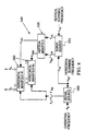
- FIG. 8 illustrates a system 180 of electronic signal generators that can generate reference, scanning and operational signals in the manifold system 158 of FIG. 7.
- the system is shown with reference to the horizontal manifold rows 160 and the vertical manifold 168 of FIG. 7.
- the system includes horizontal and vertical electronic signal generators 182 and 184 which are similar to the generator 70 of FIG. 2D.
- an operating signal s o is applied to the signal source 182
- a vertical scanning signal s vs is applied to the signal source 184
- a horizontal scanning signal s hs is applied to the signal sources 182 and 184.
- the signal source 182 generates a sum signal s o +s hs which is applied to the equal-length horizontal manifold rows 160 and the horizontal scanning signal s hs is applied to the signal source 184.
- the signal source 184 generates a sum signal s hs +s ys and the vertical scanning signal which are respectively applied to equal-length and progressive-length portions of the vertical manifold 168.
- the vertical manifold applies progressive-phase scanning signals s hs1 -s hsn . to the horizontal manifold 160.
- the horizontal manifold radiates operating signals s o which are the difference between the signals applied to the horizontal manifold.
- Phased array antennas of the invention are particularly suited for radiation and deception of independently-scanned multiple signal beams.
- two signal pairs are applied to the radiative modules 28A-28N wherein each signal pair consists of a reference signal and a scan signal.
- all of these signals are carried on single sets of photonic manifolds (e.g., the manifolds 30 and 32 of FIG. 1) and mixed and filtered in single sets of radiative modules (e.g., in the mixer 55 and filter 54 of FIG. 2C). That is, multibeam phased arrays are realized with structures that have conventionally been considered sufficient only for single beam operation.
- ⁇ o is the free space wavelength
- c and v are light velocities in free space and in optical fiber
- m is an integer.
- m is the number of 2 ⁇ phase shifts at the frequency of the scanning signal s s in the delta fiber length ⁇ L that is used to form the progressive-length manifolds of the invention.
- the frequency of a scanning signal s s is set so as to place its respective radiated beam on boresight (e.g., causing one of the phase fronts 82 and 83 to be horizontal in FIG. 1)
- the insertion of any integer number of 2 ⁇ phase shifts would still cause the beam to be on boresight.
- the beam squint of equation (4) represents beam widening that results, for example, when the bandwidth of the reference signal s r is expanded by information that it carries (e.g., pulses).
- the array element spacing D is generally selected to insure that grating lobes are not generated in a selected scan angle ⁇ that a system is designed to achieve.
- ⁇ scan angle
- the antenna beams are intended to scan ⁇ 90°
- chat D ⁇ o /2 .
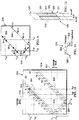
- FIG. 9 shows a signal space 200 defined by the reference and scanning signals s r and s s .
- this space it is further assumed that the frequency of the operating signal s o is constant and the bandwidth is very narrow (i.e., a narrow bandpass filter is used for the filter 54 of FIG. 2C).
- the antenna beam is on boresight when the frequencies of the reference and scanning signals are on one of the solid circles that represent each value of m.
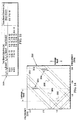
- FIG. 10 A more general view of the signal space 200 of FIG. 9 is shown by the signal space 210 of FIG. 10. This figure is similar to FIG. 9 with like elements indicated by like reference numbers. However, the effects of the mixing filter 54 of FIG. 2C are considered. This filter, of course, passes a selected operating signal s o which, in turn, was generated by mixing of the reference and scanning signals s r and s s in the mixing 54.
- An exemplary filter characteristic 220 is illustrated in FIG. 11 which indicates a pass band 222 and guard bands 224. This filter characteristic is repeated along the abscess and ordinate of the signal space 210 in FIG. 10.
- FIG. 12 illustrates an enlarged view 230 of operating regions of FIG. 10.
- Slanted lines 231 in FIG. 12 indicate regions in which the operating signal s o has a constant frequency.
- varying a scanning frequency scans its corresponding beam across a scan angle (e.g., see FIG. 1).
- horizontal movement in FIG. 12 corresponds to varying scanning frequencies and varying beam scan angles.
- vertical movement in FIG. 12 corresponds to varying reference signal frequencies and resultant frequency changes in operating signal s o . That is, vertical movement corresponds to operating bandwidth. It also corresponds to information bandwidth and to the passband and guard bands of the filter 220 of FIG. 11. If the information signal of FIG. 1 included pulses, the bandwidth of the exemplary filter 220 is preferably wide enough to transmit substantially all of the pulse's spectrum.
- Region 236 in FIG. 12 corresponds to the passband 222 of the filter 220 of FIG. 11 and is shown in bold lines. Regions 237 in FIG. 12 correspond to the guard bands 224 and are shown in broken lines.
- the operating region shown in FIG. 12 is repeated for selected operating points in FIG. 10.
- FIGS. 9-12 leads to operating processes of the invention.
- the operating regions of signal pairs (each pair being a reference signal s r and a corresponding scanning signal s s ) should be sufficiently spaced to avoid spurious operating regions.
- the two signal pairs of FIG. 10 meet this criterion because unwanted intersections are outside of any operating region and also outside of any guard band region.
- the operating regions of signal pairs should be above (in frequency) the areas corresponding to the passband and guardbands of the mixing filter 54 of FIG. 2C.
- This filter characteristic was shown in FIG. 11 and repeated along the abscissa and ordinate of the signal space 210 of FIG. 10. Extensions of these filter bands are indicated in broken lines 212 and the enclosed region labeled "leakage band". Observance of this rule assures that the signal pairs and their harmonics do not pass through the filter and produce spurious radiated signals.
- Operating regions must be below the frequency limits of electronic and photonic operational elements, e.g., that of optical detectors of FIGS. 2A and 2B. Exemplary upper operational limits 214 are shown in FIG. 10. Selected signal pairs must lie below these limits.
- FIG. 14 shows a diagram 250 that is similar to that of FIG. 10 but which is relevant to the antennas 100 and 120 of FIGS. 3 and 5.
- this diagram illustrates operating regions for the intermediate-frequency photonic manifolds 30IF and 32IF in the antennas 100 and 120 of FIGS. 3 and 5.
- the bandwidth of the filter 54 of FIG. 2C has been established as 0.6-1.25 GHz and is labeled "leakage band".
- This filter has been assumed to have -40 dB response at 200 MHz from its passband edges so that the selected operating regions will yield spurious emissions that are greater than 40 dB below the antenna beams.
- An upper frequency limit for readily-available photonic devices is shown as limit 252 at ⁇ 3GHz. Operating regions thus must be outside of the filter's leakage bands and less than the frequency limits 252.
- the delta fiber length ⁇ L has been selected as 204.78 centimeters
- the intermediate-frequency of the operating signal is 0.8-1.3 GHz
- s s1 1.54-1.66 GHz
- s s2 2.84-2.96 GHz.
- the intermediate-frequency signals can be upconverter to X-band with transmit and receive bandwidth of 500 MHz.
- a local oscillator (102 in FIG. 3) can be set at 7.1 GHz so that transmission at the radiative modules (108 in FIG. 3) is in the 7.9-8.4 GHz band.
- photonic manifolds and an associated electronic signal generator can be designed similar to the design of FIG. 14 and used as a "building block' in various phased array antennas.
- the antenna 100 of FIG. 3 is particularly suited for translating the operation of the first and second photonic manifolds down to a frequency range which enhances the availability and cost of manifold devices.
- the antenna 120 of FIG. 5 translates receive operations (e.g., beam summing and processing) down to a frequency range in which processing devices are more available and less costly.
- the magnitude of the delta fiber length ⁇ L sets the phase slope of the progressive-length manifold (manifold 32 in FIG. 1), it also sets the frequency range of the scanning signals that is required to scan an antenna beam across its designed scan angle. If the delta fiber length ⁇ L is set at a small value, it may require a scanning range that is too large to be easily realized. Conversely, if the delta fiber length ⁇ L is set at a large value, the scanning range may be undesirably small.
- the spacing between the operating regions of FIG. 10 can be controlled by selection of the delta fiber length ⁇ L. Decreasing this length causes the regions to move farther apart and increasing it causes them to move closer together. Thus the delta fiber length ⁇ L can be used as another tool in the selection of operating points for multibeam radiation and reception.
- information is carried on the reference signals that propagate through the equal-length manifolds of the invention. Accordingly, that information arrives simultaneously at each radiative module 28 of the antenna. Because it is radiated from all array elements, it generates the narrow beam that the antenna was designed to radiate. Conversely, if the information were carried on the scanning signal it would arrive at different radiative elements at different times. The array would then erroneously emit broad beams that correspond to radiation from single array elements. The arrangements of antennas of the invention therefore reduce undesirable beam broadening, i.e., reduce beam squinting.
- An exemplary two beam, two dimensional antenna with intermediate-frequency photonic manifolds scans ⁇ 70° and operates in the 7.25-7.75 GHz receive region and the 7.9-8.4 GHz transmit region.
- the operating signal s o at the manifolds is in the range of 800-1300 MHz
- beam squint is 0.02 degrees/MHz at maximum scan angle and spurious responses are ⁇ -40 dB below the main beam.
Landscapes
- Variable-Direction Aerials And Aerial Arrays (AREA)
Applications Claiming Priority (2)
| Application Number | Priority Date | Filing Date | Title |
|---|---|---|---|
| US09/081,497 US5999128A (en) | 1998-05-19 | 1998-05-19 | Multibeam phased array antennas and methods |
| US81497 | 1998-05-19 |
Publications (3)
| Publication Number | Publication Date |
|---|---|
| EP0977306A2 true EP0977306A2 (de) | 2000-02-02 |
| EP0977306A3 EP0977306A3 (de) | 2000-12-20 |
| EP0977306B1 EP0977306B1 (de) | 2002-06-26 |
Family
ID=22164568
Family Applications (1)
| Application Number | Title | Priority Date | Filing Date |
|---|---|---|---|
| EP99108661A Expired - Lifetime EP0977306B1 (de) | 1998-05-19 | 1999-05-14 | Mehrstrahl-phasengesteuerte Antenne und damit verbundenes Verfahren |
Country Status (3)
| Country | Link |
|---|---|
| US (1) | US5999128A (de) |
| EP (1) | EP0977306B1 (de) |
| DE (1) | DE69901921T2 (de) |
Families Citing this family (27)
| Publication number | Priority date | Publication date | Assignee | Title |
|---|---|---|---|---|
| US5861845A (en) * | 1998-05-19 | 1999-01-19 | Hughes Electronics Corporation | Wideband phased array antennas and methods |
| US6348890B1 (en) | 1999-08-26 | 2002-02-19 | Hrl Laboratories, Llc | Phased array antenna beamformer |
| US6452546B1 (en) * | 2000-06-14 | 2002-09-17 | Hrl Laboratories, Llc | Wavelength division multiplexing methods and apparatus for constructing photonic beamforming networks |
| US6968195B2 (en) * | 2001-03-01 | 2005-11-22 | Openwave Systems Inc. | Enhanced PDE selection |
| US7085499B2 (en) * | 2001-11-15 | 2006-08-01 | Hrl Laboratories, Llc | Agile RF-lightwave waveform synthesis and an optical multi-tone amplitude modulator |
| TW588518B (en) * | 2001-11-15 | 2004-05-21 | Hrl Lab Llc | Agile spread waveform generator |
| US20040090365A1 (en) * | 2002-11-13 | 2004-05-13 | Newberg Irwin L. | Optically frequency generated scanned active array |
| US7499653B2 (en) * | 2003-07-14 | 2009-03-03 | Hrl Laboratories, Llc | Multiple wavelength photonic oscillator |
| US7057716B2 (en) * | 2003-10-28 | 2006-06-06 | Hrl Laboratories, Llc | White cell antenna beamformers |
| US7822082B2 (en) * | 2004-01-27 | 2010-10-26 | Hrl Laboratories, Llc | Wavelength reconfigurable laser transmitter tuned via the resonance passbands of a tunable microresonator |
| US20080225375A1 (en) * | 2004-09-07 | 2008-09-18 | Raytheon Company | Optically frequency generated scanned active array |
| US7084811B1 (en) | 2004-09-14 | 2006-08-01 | Hrl Laboratories, Llc | Agile optical wavelength selection for antenna beamforming |
| US7391367B2 (en) * | 2004-09-28 | 2008-06-24 | Raytheon Company | Optically frequency generated scanned active array |
| GB0423394D0 (en) * | 2004-10-21 | 2004-11-24 | Eads Astrium Ltd | Improvements in the flexibility of communications satellite payloads |
| US7603140B2 (en) * | 2005-05-17 | 2009-10-13 | Alcatel-Lucent Usa Inc. | Method of phase sweep transmit diversity (PSTD) and apparatus for providing PSTD |
| US7898464B1 (en) * | 2006-04-11 | 2011-03-01 | Lockheed Martin Corporation | System and method for transmitting signals via photonic excitation of a transmitter array |
| US9660339B2 (en) * | 2010-12-04 | 2017-05-23 | Chian Chiu Li | Beam steering and manipulating apparatus and method |
| WO2013112214A2 (en) | 2011-10-18 | 2013-08-01 | California Institute Of Technology | Efficient active multi-drive radiator |
| US10601131B2 (en) * | 2011-12-02 | 2020-03-24 | Chian Chiu Li | Beam steering and manipulating apparatus and method |
| US8861971B2 (en) | 2012-01-05 | 2014-10-14 | Harris Corporation | Phased antenna array with electro-optic readout circuit with multiplexing and related methods |
| US9921255B2 (en) | 2012-02-13 | 2018-03-20 | California Institute Of Technology | Sensing radiation metrics through mode-pickup sensors |
| US9686070B2 (en) | 2012-02-17 | 2017-06-20 | California Institute Of Technology | Dynamic polarization modulation and control |
| WO2014018927A1 (en) * | 2012-07-26 | 2014-01-30 | California Institute Of Technology | Optically driven active radiator |
| RU2654994C1 (ru) * | 2017-03-17 | 2018-05-23 | Акционерное общество "Ижевский радиозавод" | Приемная многолучевая активная фазированная антенная решетка |
| RU2666577C1 (ru) * | 2017-12-01 | 2018-09-11 | Акционерное общество "Ижевский радиозавод" | Приемная многолучевая активная фазированная антенная решетка |
| FR3089696B1 (fr) * | 2018-12-11 | 2020-11-13 | Thales Sa | Dispositif de déphasage mécanique large bande en onde guidée |
| CN112910560B (zh) * | 2021-01-11 | 2021-12-31 | 浙江大学 | 一种opa与光学相控阵结合的激光通信方法及通信系统 |
Family Cites Families (5)
| Publication number | Priority date | Publication date | Assignee | Title |
|---|---|---|---|---|
| US3090928A (en) * | 1958-01-02 | 1963-05-21 | Hughes Aircraft Co | Apparatus for generating plurality of signals having variable phase difference |
| BE792171A (fr) * | 1971-09-17 | 1973-06-01 | Int Standard Electric Corp | Antenne d'exploration de trame |
| US5933113A (en) * | 1996-09-05 | 1999-08-03 | Raytheon Company | Simultaneous multibeam and frequency active photonic array radar apparatus |
| US5977911A (en) * | 1996-12-30 | 1999-11-02 | Raytheon Company | Reactive combiner for active array radar system |
| US5861845A (en) * | 1998-05-19 | 1999-01-19 | Hughes Electronics Corporation | Wideband phased array antennas and methods |
-
1998
- 1998-05-19 US US09/081,497 patent/US5999128A/en not_active Expired - Lifetime
-
1999
- 1999-05-14 DE DE69901921T patent/DE69901921T2/de not_active Expired - Lifetime
- 1999-05-14 EP EP99108661A patent/EP0977306B1/de not_active Expired - Lifetime
Also Published As
| Publication number | Publication date |
|---|---|
| EP0977306B1 (de) | 2002-06-26 |
| EP0977306A3 (de) | 2000-12-20 |
| US5999128A (en) | 1999-12-07 |
| DE69901921T2 (de) | 2003-02-27 |
| DE69901921D1 (de) | 2002-08-01 |
Similar Documents
| Publication | Publication Date | Title |
|---|---|---|
| EP0977306B1 (de) | Mehrstrahl-phasengesteuerte Antenne und damit verbundenes Verfahren | |
| EP0959521B1 (de) | Breitband-phasengesteuerte Antenne und damit verbundenes Verfahren | |
| US6535165B2 (en) | Phased array antenna beamformer | |
| US5933113A (en) | Simultaneous multibeam and frequency active photonic array radar apparatus | |
| DE68924590T2 (de) | Optischer strahlformer für eine hochfrequenz-gruppenantenne. | |
| US4258363A (en) | Phased array radar | |
| US5977910A (en) | Multibeam phased array antenna system | |
| US5818386A (en) | Design of an electronic beam forming network for phased array applications | |
| US9917651B2 (en) | Feed signal generation for a phased array antenna | |
| US5134417A (en) | Plural frequency matrix multiplexer | |
| US4388626A (en) | Phased array antennas using frequency multiplication for reduced numbers of phase shifters | |
| US6690326B2 (en) | Wide bandwidth phased array antenna system | |
| Wang et al. | Frequency-comb-steered ultrawideband quasi-true-time-delay beamformer for integrated sensing and communication | |
| Ji et al. | Receive mode of optical signal processing multibeam array antennas | |
| US20240361434A1 (en) | Multi-beam scanning systems | |
| CN117938271A (zh) | 微波光子一体化接收处理装置 | |
| Thai et al. | A novel simplified dual beam-former using multichannel chirped fiber grating and tunable optical delay lines | |
| Paul | Optical beam forming and steering for phased-array antenna | |
| Frankel et al. | Dynamic null steering in an ultrawideband time-steered array antenna | |
| Paul et al. | Optical beam forming and steering technologies for satellite phased array antennas | |
| CN120128232A (zh) | 一种收发共用的光控波束形成装置和方法 | |
| Lee | RF photonics for beamforming and array applications | |
| DE4001884A1 (de) | Antenne mit Mehrfach-Empfangsstrahl | |
| TANGONAN et al. | System design and performance of wideband photonic phased array antennas | |
| Paul et al. | True time-delay photonic beamforming with fine steerability and frequency-agility for spaceborne phased-arrays: a proof-of-concept demonstration |
Legal Events
| Date | Code | Title | Description |
|---|---|---|---|
| PUAI | Public reference made under article 153(3) epc to a published international application that has entered the european phase |
Free format text: ORIGINAL CODE: 0009012 |
|
| AK | Designated contracting states |
Kind code of ref document: A2 Designated state(s): DE FR GB IT |
|
| AX | Request for extension of the european patent |
Free format text: AL;LT;LV;MK;RO;SI |
|
| K1C3 | Correction of patent application (complete document) published |
Effective date: 20000202 |
|
| PUAL | Search report despatched |
Free format text: ORIGINAL CODE: 0009013 |
|
| AK | Designated contracting states |
Kind code of ref document: A3 Designated state(s): AT BE CH CY DE DK ES FI FR GB GR IE IT LI LU MC NL PT SE |
|
| AX | Request for extension of the european patent |
Free format text: AL;LT;LV;MK;RO;SI |
|
| 17P | Request for examination filed |
Effective date: 20010606 |
|
| AKX | Designation fees paid |
Free format text: DE FR GB IT |
|
| GRAG | Despatch of communication of intention to grant |
Free format text: ORIGINAL CODE: EPIDOS AGRA |
|
| GRAG | Despatch of communication of intention to grant |
Free format text: ORIGINAL CODE: EPIDOS AGRA |
|
| GRAH | Despatch of communication of intention to grant a patent |
Free format text: ORIGINAL CODE: EPIDOS IGRA |
|
| 17Q | First examination report despatched |
Effective date: 20010921 |
|
| GRAH | Despatch of communication of intention to grant a patent |
Free format text: ORIGINAL CODE: EPIDOS IGRA |
|
| GRAA | (expected) grant |
Free format text: ORIGINAL CODE: 0009210 |
|
| AK | Designated contracting states |
Kind code of ref document: B1 Designated state(s): DE FR GB IT |
|
| REG | Reference to a national code |
Ref country code: GB Ref legal event code: FG4D |
|
| REF | Corresponds to: |
Ref document number: 69901921 Country of ref document: DE Date of ref document: 20020801 |
|
| ET | Fr: translation filed | ||
| PLBE | No opposition filed within time limit |
Free format text: ORIGINAL CODE: 0009261 |
|
| STAA | Information on the status of an ep patent application or granted ep patent |
Free format text: STATUS: NO OPPOSITION FILED WITHIN TIME LIMIT |
|
| 26N | No opposition filed |
Effective date: 20030327 |
|
| REG | Reference to a national code |
Ref country code: FR Ref legal event code: PLFP Year of fee payment: 18 |
|
| PGFP | Annual fee paid to national office [announced via postgrant information from national office to epo] |
Ref country code: DE Payment date: 20160520 Year of fee payment: 18 Ref country code: GB Payment date: 20160520 Year of fee payment: 18 |
|
| PGFP | Annual fee paid to national office [announced via postgrant information from national office to epo] |
Ref country code: FR Payment date: 20160520 Year of fee payment: 18 Ref country code: IT Payment date: 20160525 Year of fee payment: 18 |
|
| REG | Reference to a national code |
Ref country code: DE Ref legal event code: R119 Ref document number: 69901921 Country of ref document: DE |
|
| GBPC | Gb: european patent ceased through non-payment of renewal fee |
Effective date: 20170514 |
|
| REG | Reference to a national code |
Ref country code: FR Ref legal event code: ST Effective date: 20180131 |
|
| PG25 | Lapsed in a contracting state [announced via postgrant information from national office to epo] |
Ref country code: GB Free format text: LAPSE BECAUSE OF NON-PAYMENT OF DUE FEES Effective date: 20170514 Ref country code: DE Free format text: LAPSE BECAUSE OF NON-PAYMENT OF DUE FEES Effective date: 20171201 |
|
| PG25 | Lapsed in a contracting state [announced via postgrant information from national office to epo] |
Ref country code: IT Free format text: LAPSE BECAUSE OF NON-PAYMENT OF DUE FEES Effective date: 20170514 Ref country code: FR Free format text: LAPSE BECAUSE OF NON-PAYMENT OF DUE FEES Effective date: 20170531 |