EP0977310A2 - Elektrischer Keilverbinder mit isolationsdurchdringendem Keil und Schutzumschlag - Google Patents
Elektrischer Keilverbinder mit isolationsdurchdringendem Keil und Schutzumschlag Download PDFInfo
- Publication number
- EP0977310A2 EP0977310A2 EP99114221A EP99114221A EP0977310A2 EP 0977310 A2 EP0977310 A2 EP 0977310A2 EP 99114221 A EP99114221 A EP 99114221A EP 99114221 A EP99114221 A EP 99114221A EP 0977310 A2 EP0977310 A2 EP 0977310A2
- Authority
- EP
- European Patent Office
- Prior art keywords
- wedge
- main body
- electrical
- connector
- flap
- Prior art date
- Legal status (The legal status is an assumption and is not a legal conclusion. Google has not performed a legal analysis and makes no representation as to the accuracy of the status listed.)
- Withdrawn
Links
Images

Classifications
-
- H—ELECTRICITY
- H01—ELECTRIC ELEMENTS
- H01R—ELECTRICALLY-CONDUCTIVE CONNECTIONS; STRUCTURAL ASSOCIATIONS OF A PLURALITY OF MUTUALLY-INSULATED ELECTRICAL CONNECTING ELEMENTS; COUPLING DEVICES; CURRENT COLLECTORS
- H01R4/00—Electrically-conductive connections between two or more conductive members in direct contact, i.e. touching one another; Means for effecting or maintaining such contact; Electrically-conductive connections having two or more spaced connecting locations for conductors and using contact members penetrating insulation
- H01R4/28—Clamped connections, spring connections
- H01R4/50—Clamped connections, spring connections utilising a cam, wedge, cone or ball also combined with a screw
- H01R4/5083—Clamped connections, spring connections utilising a cam, wedge, cone or ball also combined with a screw using a wedge
-
- H—ELECTRICITY
- H01—ELECTRIC ELEMENTS
- H01R—ELECTRICALLY-CONDUCTIVE CONNECTIONS; STRUCTURAL ASSOCIATIONS OF A PLURALITY OF MUTUALLY-INSULATED ELECTRICAL CONNECTING ELEMENTS; COUPLING DEVICES; CURRENT COLLECTORS
- H01R4/00—Electrically-conductive connections between two or more conductive members in direct contact, i.e. touching one another; Means for effecting or maintaining such contact; Electrically-conductive connections having two or more spaced connecting locations for conductors and using contact members penetrating insulation
- H01R4/24—Connections using contact members penetrating or cutting insulation or cable strands
- H01R4/2404—Connections using contact members penetrating or cutting insulation or cable strands the contact members having teeth, prongs, pins or needles penetrating the insulation
- H01R4/2412—Connections using contact members penetrating or cutting insulation or cable strands the contact members having teeth, prongs, pins or needles penetrating the insulation actuated by insulated cams or wedges
Definitions
- the present invention relates to electrical connectors and, more particularly, to an electrical wedge connector.
- U.K. patent application publication No. GB 2065994 discloses an electrical wedge connector with an insulation piercing wedge.
- U.S. Patent No. 5,679,031 discloses a wedge connector with retention barbs on its shell.
- an electrical wedge connector comprising a shell and a wedge.
- the wedge is sized and shaped to be inserted into the shell.
- the wedge comprises a main body with two conductor contact surfaces on opposite sides of the main body and at least one flap extending over a first one of the conductor contact surfaces at a first one of the sides.
- a gap is provided between the first conductor contact surface and the flap which receives an electrical conductor therein.
- an electrical connector wedge comprising a main body, a first movable flap, and means for piercing through electrical insulation of a first electrical conductor.
- the main body has two conductor contact surfaces on opposite sides of the main body.
- the first movable flap extends from the main body and is positionable over a first one of the conductor contact surfaces to form a pocket for receiving a first electrical conductor therein.
- the means for piercing is adapted to pierce through electrical insulation of the first electrical conductor and electrically contact an electrical conducting section of the first conductor.
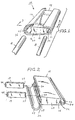
- FIG. 1 there is shown an exploded perspective view of an electrical wedge connector 10 incorporating features of the present invention and two electrical conductors A,B.
- an electrical wedge connector 10 incorporating features of the present invention and two electrical conductors A,B.
- the connector 10 comprises a shell 12 and a wedge 14.
- the shell 12 in the embodiment shown, is a one-piece metal member with a general cross-sectional "C" shape and a general wedge shaped profile from front to rear.
- the wedge 14 generally comprises a frame 16 and bars 18, 19.
- the frame 16 is comprised of dielectric material, such as molded plastic or polymer material.
- the frame 16 comprises a main body section 20 and two flaps 22, 24 on opposite side of the main body section 20. In an alternate embodiment more than two flaps could be provided or only one flap on one side of the main body section need be provided.
- the main body section 20 includes curved conductor contact surfaces 26, 28 and slots 30 extending between the surfaces 26, 28.
- the flaps 22, 24 are integrally formed with the main body section 20. However, in an alternate embodiment the flaps could be attached to the main body section rather than integrally formed therewith.
- a living hinge section 32 connects each of the flaps 22, 24 to the main body section 20.
- the flaps 22, 24 extend from the main body section 20 in a general cantilever fashion and can be moved relative to the main body section 20 at the living hinge sections 32.
- the flaps 22, 24 have a general cross-sectional semi-circular arc shape.
- the first flap 22 extends over the first conductor contact surface 26.
- the second flap 24 extends over the second conductor contact surface 28.
- two spaces or gaps 34, 36 are formed for receiving the conductors B,A therein, respectively.
- the bars 18, 19 are substantially similar, except for their length, and are preferably comprised of electrically conductive metal. Opposite ends of the bars 18, 19 have insulation piercing teeth 38, 40. However, in alternate embodiments other types or numbers of electrically conductive members could be provided on the frame 16. In this embodiment the second flap 24 is folded back and the bars 18, 19 are inserted into the slots 30. In an alternate embodiment the frame 16 could be molded onto the bars 18, 19. The teeth 38, 40 extend out opposite ends of the slots 30 into the conductor receiving spaces 34, 36. The flaps 22, 24 can be folded back at their living hinge connections 32 to insert the conductors A, B into the gaps 36, 34. Then the wedge 14 and conductors A, B are inserted in the shell 12.
- the flaps 22, 24 protect the insulation D on the conductors A, B from being damaged by the shell 12 as the wedge is inserted into the shell.
- the flaps 22, 24 also push the conductors B, A against the teeth 38, 40 as the flaps are pushed in by the inward wedging action of the shell.
- the teeth 38, 40 are able to pierce through the insulation D on the conductors B, A and make direct electrical contact with the conductive sections C of the conductors.
- an electrical connection can be made between two insulated conductors by a wedge connector without first removing the electrical insulation layer and wherein the electrical connection is not made through the shell.
- electrical connection could also be made through the shell.
- the wedge 100 is a one-piece member comprised of an electrically conductive material, such as aluminum.
- the wedge 100 has a main body 102 and two flaps 104, 106.
- the main body 102 has the two flaps 104, 106 formed integrally therewith, such as by means of an extrusion process.
- the main body 102 has two conductor contact surfaces 108, 110.
- the surfaces 108, 110 have teeth 112 therealong and recessed areas 114.
- the recessed areas 114 are provided to reduce the area of contact at the surfaces 108, 110 so that the teeth 112 can more easily pierce through insulation on the conductors.
- the wedge does not need separate insulation piercing members.
Landscapes
- Connections By Means Of Piercing Elements, Nuts, Or Screws (AREA)
- Insulation, Fastening Of Motor, Generator Windings (AREA)
- Coupling Device And Connection With Printed Circuit (AREA)
Applications Claiming Priority (2)
| Application Number | Priority Date | Filing Date | Title |
|---|---|---|---|
| US09/123,685 US5944564A (en) | 1998-07-28 | 1998-07-28 | Electrical wedge connector with insulation piercing wedge and protective flaps |
| US123685 | 1998-07-28 |
Publications (2)
| Publication Number | Publication Date |
|---|---|
| EP0977310A2 true EP0977310A2 (de) | 2000-02-02 |
| EP0977310A3 EP0977310A3 (de) | 2001-05-16 |
Family
ID=22410236
Family Applications (1)
| Application Number | Title | Priority Date | Filing Date |
|---|---|---|---|
| EP99114221A Withdrawn EP0977310A3 (de) | 1998-07-28 | 1999-07-26 | Elektrischer Keilverbinder mit isolationsdurchdringendem Keil und Schutzumschlag |
Country Status (7)
| Country | Link |
|---|---|
| US (1) | US5944564A (de) |
| EP (1) | EP0977310A3 (de) |
| JP (1) | JP2000058147A (de) |
| CN (1) | CN1261731A (de) |
| AU (1) | AU4233899A (de) |
| BR (1) | BR9902898A (de) |
| CA (1) | CA2278431A1 (de) |
Cited By (1)
| Publication number | Priority date | Publication date | Assignee | Title |
|---|---|---|---|---|
| FR3086808A1 (fr) * | 2018-10-02 | 2020-04-03 | Commissariat A L'energie Atomique Et Aux Energies Alternatives | Connecteur |
Families Citing this family (10)
| Publication number | Priority date | Publication date | Assignee | Title |
|---|---|---|---|---|
| AUPQ104099A0 (en) * | 1999-06-18 | 1999-07-08 | Resmed Limited | Forehead support for facial mask |
| US6146216A (en) * | 1999-04-12 | 2000-11-14 | Timsit; Roland Sion | Electrical wire connector |
| US6322402B1 (en) * | 2000-06-28 | 2001-11-27 | Fci Usa, Inc. | Insulation piercing wedge connector with snap in blades |
| US7223133B2 (en) * | 2004-12-30 | 2007-05-29 | Fci Americas Technology, Inc. | Electrical conductor wedge connector splice |
| US7121868B2 (en) * | 2004-12-30 | 2006-10-17 | Fci Americas Technology, Inc. | Electrical splice connector |
| US7997943B2 (en) * | 2006-05-18 | 2011-08-16 | Tyco Electronics Corporation | Transverse wedge connector |
| US7341495B1 (en) * | 2006-12-06 | 2008-03-11 | Fci Americas Technology, Inc. | Electrical wedge connector heat dissipating design |
| US9287673B2 (en) | 2013-12-06 | 2016-03-15 | Tyco Electronics Corporation | Insulation piercing connectors and methods and connections including same |
| US10840615B2 (en) | 2018-06-28 | 2020-11-17 | Te Connectivity Corporation | Connection enclosure assemblies, connector systems and methods for forming an enclosed connection between conductors |
| US11431114B2 (en) | 2020-02-14 | 2022-08-30 | Te Connectivity Solutions Gmbh | Enclosed connection systems for forming an enclosed connection between conductors, and methods including same |
Family Cites Families (8)
| Publication number | Priority date | Publication date | Assignee | Title |
|---|---|---|---|---|
| US2801400A (en) * | 1954-08-04 | 1957-07-30 | Silec Liaisons Elec | Junction device for electrical conductors |
| US3329928A (en) * | 1964-10-01 | 1967-07-04 | Amp Inc | Adjustable wedge-type electrical connector |
| NO147324C (no) * | 1979-04-09 | 1983-03-16 | Pfisterer Elektrotech Karl | Avspenningsklemme for isolerte luftledninger |
| GB2065994B (en) * | 1979-12-12 | 1983-07-27 | Bicc Burdny Ltd | Wedge for use in electric connectors |
| US4415222A (en) * | 1981-01-19 | 1983-11-15 | Mario Polidori | Electrical connector |
| US5679031A (en) * | 1995-08-23 | 1997-10-21 | Framatome Connectors Usa Inc. | Electrical wedge connector with retention barbs |
| ES2116224B1 (es) * | 1996-05-31 | 1999-04-01 | Framatome Connectors Espana S | Conector electrico para la conexion de conductores electricos. |
| US5820422A (en) * | 1997-07-08 | 1998-10-13 | Framatome Connectors Usa Inc. | Cover for an electrical wedge connector |
-
1998
- 1998-07-28 US US09/123,685 patent/US5944564A/en not_active Expired - Fee Related
-
1999
- 1999-07-09 JP JP11196666A patent/JP2000058147A/ja not_active Withdrawn
- 1999-07-22 CA CA002278431A patent/CA2278431A1/en not_active Abandoned
- 1999-07-26 EP EP99114221A patent/EP0977310A3/de not_active Withdrawn
- 1999-07-27 BR BR9902898-0A patent/BR9902898A/pt not_active Application Discontinuation
- 1999-07-28 AU AU42338/99A patent/AU4233899A/en not_active Abandoned
- 1999-07-28 CN CN99110702A patent/CN1261731A/zh active Pending
Cited By (3)
| Publication number | Priority date | Publication date | Assignee | Title |
|---|---|---|---|---|
| FR3086808A1 (fr) * | 2018-10-02 | 2020-04-03 | Commissariat A L'energie Atomique Et Aux Energies Alternatives | Connecteur |
| EP3633794A1 (de) | 2018-10-02 | 2020-04-08 | Commissariat à l'énergie atomique et aux énergies alternatives | Anschluss |
| US10957996B2 (en) | 2018-10-02 | 2021-03-23 | Commissariat A L'energie Atomique Et Aux Energies Alternatives | Connector made of an electrically insulating material to electrically connect a main conductor and a secondary conductor |
Also Published As
| Publication number | Publication date |
|---|---|
| EP0977310A3 (de) | 2001-05-16 |
| JP2000058147A (ja) | 2000-02-25 |
| AU4233899A (en) | 2000-02-17 |
| CN1261731A (zh) | 2000-08-02 |
| US5944564A (en) | 1999-08-31 |
| BR9902898A (pt) | 2000-01-04 |
| CA2278431A1 (en) | 2000-01-28 |
Similar Documents
| Publication | Publication Date | Title |
|---|---|---|
| US5785557A (en) | Electrical connector with protection for electrical contacts | |
| EP0608813B1 (de) | Zweiteiliges Abschirmgehäuse für einen Verbinder | |
| US6478609B1 (en) | Strain relief assembly | |
| US5207603A (en) | Dual thickness blade type electrical terminal | |
| US5009614A (en) | Shielded cable assembly with floating ground | |
| JP3775557B2 (ja) | コネクタ | |
| EP0699355B1 (de) | Verdrahtungsadapter zum anschliessen eines kabels | |
| US5944564A (en) | Electrical wedge connector with insulation piercing wedge and protective flaps | |
| EP1538715A3 (de) | Telekommunikationsverbinder mit verbesserter Leistung | |
| EP0806814A3 (de) | Elektrischer Steckverbinder mit verbesserten Kontaktrückhaltemitteln | |
| CA2204293A1 (en) | Female electrical contact terminal with a reinforced transition region | |
| US5746620A (en) | Electrical connector including means for terminating wires | |
| AU7901394A (en) | Electrical connectors | |
| JPS5833671B2 (ja) | ハンダナシデンセンコネクタ | |
| JP2611901B2 (ja) | 楔形コネクタ | |
| US6361379B1 (en) | Electrical connector | |
| US4373773A (en) | Socket type contact assembly | |
| US6095839A (en) | Electrical connector | |
| US5944565A (en) | Electrical wedge connector with insulation piercing wedge and nest housing | |
| EP1294055A3 (de) | Steckverbinderanordnung mit einer Federbuchse und einem Doppelkontakt mit einem Paar von versetzten Kontaktelementen | |
| US6273765B1 (en) | Wedge connector with insulation perforating device | |
| US6065987A (en) | Electrical terminal | |
| US6093065A (en) | Electrical wedge connector having sleeve with wedge locking tabs | |
| US4472014A (en) | Insulation displacement connector for flat cable | |
| GB2173361A (en) | An improved electric plug assembly |
Legal Events
| Date | Code | Title | Description |
|---|---|---|---|
| PUAI | Public reference made under article 153(3) epc to a published international application that has entered the european phase |
Free format text: ORIGINAL CODE: 0009012 |
|
| AK | Designated contracting states |
Kind code of ref document: A2 Designated state(s): AT BE CH CY DE DK ES FI FR GB GR IE IT LI LU MC NL PT SE |
|
| AX | Request for extension of the european patent |
Free format text: AL;LT;LV;MK;RO;SI |
|
| PUAL | Search report despatched |
Free format text: ORIGINAL CODE: 0009013 |
|
| AK | Designated contracting states |
Kind code of ref document: A3 Designated state(s): AT BE CH CY DE DK ES FI FR GB GR IE IT LI LU MC NL PT SE |
|
| AX | Request for extension of the european patent |
Free format text: AL;LT;LV;MK;RO;SI |
|
| 17P | Request for examination filed |
Effective date: 20010917 |
|
| AKX | Designation fees paid |
Free format text: AT BE CH CY DE DK ES FI FR GB GR IE IT LI LU MC NL PT SE |
|
| 17Q | First examination report despatched |
Effective date: 20030324 |
|
| STAA | Information on the status of an ep patent application or granted ep patent |
Free format text: STATUS: THE APPLICATION IS DEEMED TO BE WITHDRAWN |
|
| 18D | Application deemed to be withdrawn |
Effective date: 20030201 |