EP0977331A1 - Rigid, plastic enclosure for electrical devices - Google Patents
Rigid, plastic enclosure for electrical devices Download PDFInfo
- Publication number
- EP0977331A1 EP0977331A1 EP99401915A EP99401915A EP0977331A1 EP 0977331 A1 EP0977331 A1 EP 0977331A1 EP 99401915 A EP99401915 A EP 99401915A EP 99401915 A EP99401915 A EP 99401915A EP 0977331 A1 EP0977331 A1 EP 0977331A1
- Authority
- EP
- European Patent Office
- Prior art keywords
- rear panel
- panel
- panels
- rigid
- side panels
- Prior art date
- Legal status (The legal status is an assumption and is not a legal conclusion. Google has not performed a legal analysis and makes no representation as to the accuracy of the status listed.)
- Granted
Links
- 230000002093 peripheral effect Effects 0.000 claims description 5
- 238000010079 rubber tapping Methods 0.000 claims description 4
- 239000000463 material Substances 0.000 claims description 3
- 238000007789 sealing Methods 0.000 claims description 2
- 238000004519 manufacturing process Methods 0.000 description 4
- 238000000465 moulding Methods 0.000 description 2
- 238000003754 machining Methods 0.000 description 1
- 239000002184 metal Substances 0.000 description 1
- 229920000728 polyester Polymers 0.000 description 1
- 230000000717 retained effect Effects 0.000 description 1
Images
Classifications
-
- F—MECHANICAL ENGINEERING; LIGHTING; HEATING; WEAPONS; BLASTING
- F16—ENGINEERING ELEMENTS AND UNITS; GENERAL MEASURES FOR PRODUCING AND MAINTAINING EFFECTIVE FUNCTIONING OF MACHINES OR INSTALLATIONS; THERMAL INSULATION IN GENERAL
- F16B—DEVICES FOR FASTENING OR SECURING CONSTRUCTIONAL ELEMENTS OR MACHINE PARTS TOGETHER, e.g. NAILS, BOLTS, CIRCLIPS, CLAMPS, CLIPS OR WEDGES; JOINTS OR JOINTING
- F16B12/00—Jointing of furniture or the like, e.g. hidden from exterior
- F16B12/44—Leg joints; Corner joints
- F16B12/46—Non-metal corner connections
-
- H—ELECTRICITY
- H02—GENERATION; CONVERSION OR DISTRIBUTION OF ELECTRIC POWER
- H02B—BOARDS, SUBSTATIONS OR SWITCHING ARRANGEMENTS FOR THE SUPPLY OR DISTRIBUTION OF ELECTRIC POWER
- H02B1/00—Frameworks, boards, panels, desks, casings; Details of substations or switching arrangements
- H02B1/26—Casings; Parts thereof or accessories therefor
- H02B1/30—Cabinet-type casings; Parts thereof or accessories therefor
-
- H—ELECTRICITY
- H02—GENERATION; CONVERSION OR DISTRIBUTION OF ELECTRIC POWER
- H02B—BOARDS, SUBSTATIONS OR SWITCHING ARRANGEMENTS FOR THE SUPPLY OR DISTRIBUTION OF ELECTRIC POWER
- H02B1/00—Frameworks, boards, panels, desks, casings; Details of substations or switching arrangements
- H02B1/26—Casings; Parts thereof or accessories therefor
- H02B1/50—Pedestal- or pad-mounted casings; Parts thereof or accessories therefor
Definitions
- the present invention relates to a rigid plastic envelope having to house electrical equipment and comprising a vertical rear panel and vertical side panels orthogonal to the rear panel.
- the rear panel is attached to the side panels using screws and nuts.
- This assembly therefore requires simple means, but requires specific machining of the side panels to adapt their shape so that their edges can be embedded and lean against the rear panel.
- the invention therefore aims to simplify the manufacture of an envelope rigid plastic while aiming for a quick and resistant assembly of its side panels to its rear panel.
- the nestable end of the rigid tab is parallel to the rear panel, and the envelope comprises a bottom panel and / or a nested roof by flanges on the lower and / or upper ends of the side panels.
- the rigid tab may advantageously have between its ends a stepped part backed by ribs of the rear panel and the side panel and be shaped at its screwable end in stirrup, the wings of which ensure positioning on the molded boss on the rear panel.
- a peripheral seal can advantageously be housed behind the legs rigid in a groove in the rear panel or side panel. This joint is advantageously identical to that which seals the envelope door.
- the invention also relates to a plastic envelope composed of panels molded, namely a vertical rear panel, vertical side panels and orthogonal to the rear panel, and horizontal bottom and roof panels and orthogonal to the rear panel, in which the rear panel is assembled to side panels by at least one rigid fixing lug provided with a nestable end and a screwable end intended to be respectively mounted on the side and rear panels, the bottom and roof panels being identical to each other and fitted on the side panels confirming the fitting of the rigid legs of fixation.
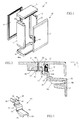
- the cabinet 1 illustrated in FIG. 1 is made of rigid plastic and is intended to house electrical equipment.
- the term "cabinet” refers to the cabinets themselves say, cases or similar envelopes suitable for receiving devices electric.
- the cabinet 1 comprises an envelope 10 formed by the assembly of a rear vertical panel 11, vertical side panels 12 and horizontal panels bottom 14 and roof 15, the panels 12, 14 and 15 being perpendicular to the rear panel 11.
- the casing 10 has an opening on the front which can be closed by a pivoting door 20 with the addition of a peripheral seal on a rim of the opening which consists of a succession of rims provided for the front of the various panels.
- the door 20 is advantageously constituted by an identical panel 21 to the rear panel 11 which is opposite it.
- An invisible hinge is attached to inside the panel 21 for fixing the door and pivoting it on an edge 30 one of the side panels 12.
- a handle 40 is assembled on the outside of the panel 21 to operate the door.
- the panels 11-15 and 21 are molded in material plastic, for example polyester.
- the identical configuration of the rear panel 11 and the door panel 21 allows them to be produced with a single manufacturing mold, so as to reduce production costs.
- the same identical manufacturing principle is applied to the opposite side panels 12, as well as to the opposite panels of bottom 14 and roof 15.
- the bottom 14 and roof 15 panels fit together on the ends low and high respectively of the side panels 12.
- the assembly of the rear panel 11 to a side panel 12 is made of inner side of the enclosure by means of at least one rigid fixing lug 50 (see Figures 2 and 3).
- the side panel 12 comprises a housing 60 coming from molding, and the rear panel 11 has a molded support part 61, such as a boss, and provided with a recess 62, the recess 62 and the housing 60 being located in a same horizontal plane P in assembly position.
- the rigid fixing lug 50 as illustrated in FIG. 3, includes a metal body 51 which has a nestable end 52 and a screwable end 53 intended to be fixed respectively to panels 12 and 11.
- the nestable end 52 is fixed to the panel 12 before the screwable end 53 is fixed to the panel 11.
- the body 51 of the fixing lug is advantageously stepped in its part 57 located between the ends 52, 53 to lean against ribs 12a, 11a of the panels lateral 12 and rear 11. This results in good rigidity and good support of the Exhibit 50.
- the nestable end 52 is intended to be inserted by nesting in the convergent undercut housing 60 of the side panel 12 and is provided with 54 feet to provide better seating.
- the volume of the housing 60 is adapted to the thickness and at the height of the end 52 so that the latter is retained there by simple jamming.
- the screwable end 53 offers a flat face provided with a through hole 55 and two wings 56 substantially orthogonal to the flat face in the manner of a stirrup for straddle and position itself on the boss 61 of the rear panel, so as to make coincide the hole 55 with the recess 62.
- the alignment of the hole 55 with the recess 62 allows to introduce a screw 63, preferably self-tapping, to fix the end 53 from tab 50 to the rear panel.
- the end 52 of the tab 50 is first of all inserted and fitted into the housing 60 of the side panel 12. Once this end 52 in place, the panel side 12 is approached from the rear panel 11 perpendicular thereto, so to position the recess 62 opposite the hole 55, the end 53 being applied on the boss 61. The end 53 is then fixed to the rear panel 11 by the screwing of the self-tapping screw 63 in the recess 62. It should be observed that the socket flanges 14a, 15a of the bottom 14 and roof 15 panels on the ends low and high side panels contributes to the rigidity of the assembly, confirming the fitting of the ends 52 of the legs into their housings 60.
- Sealing between the two panels is achieved by means of a peripheral seal 70 which is located behind the fixing lugs 50 and which is put under pressure by applying and maintaining the ends 53 of the legs against the bosses 61.
- the seal is either made integral with an edge 71 of the side panel 12, to ability to cooperate with a groove 72 in the rear panel 11, as illustrated in the figure 2, either housed in such a groove 72 to cooperate with a face or the edge of a edge of the side panel 12.
- the seal 70 is identical to that which seals the door panel 21.
Landscapes
- Engineering & Computer Science (AREA)
- General Engineering & Computer Science (AREA)
- Power Engineering (AREA)
- Mechanical Engineering (AREA)
- Casings For Electric Apparatus (AREA)
- Patch Boards (AREA)
Abstract
Description
La présente invention concerne une enveloppe en matière plastique rigide devant loger des appareillages électriques et comportant un panneau arrière vertical et des panneaux latéraux verticaux et orthogonaux au panneau arrière.The present invention relates to a rigid plastic envelope having to house electrical equipment and comprising a vertical rear panel and vertical side panels orthogonal to the rear panel.
Actuellement, la fixation du panneau arrière aux panneaux latéraux est réalisée au moyen de vis et d'écrous. Cette assemblage demande par conséquent des moyens simples, mais nécessite cependant un usinage spécifique des panneaux latéraux pour adapter leur forme de manière à ce que leurs bords puissent s'encastrer et s'appuyer contre le panneau arrière.Currently, the rear panel is attached to the side panels using screws and nuts. This assembly therefore requires simple means, but requires specific machining of the side panels to adapt their shape so that their edges can be embedded and lean against the rear panel.
L'invention a par conséquent pour but de simplifier la fabrication d'une enveloppe en matière plastique rigide tout en visant un assemblage rapide et résistant de ses panneaux latéraux à son panneau arrière.The invention therefore aims to simplify the manufacture of an envelope rigid plastic while aiming for a quick and resistant assembly of its side panels to its rear panel.
Selon l'invention,
- l'enveloppe comprend des panneaux arrière et latéraux moulés,
- le panneau arrière est assemblé aux panneaux latéraux par au moins une patte rigide de fixation dotée d'une extrémité emboítable et d'une extrémité vissable destinées à être respectivement montées sur les panneaux latéral et vertical,
- l'un des deux panneaux, notamment le panneau latéral, comporte un logement venu de moulage, et l'autre panneau, notamment le panneau arrière, comporte un bossage moulé pourvu d'un évidement pour coopérer avec une vis passant dans un trou de la patte rigide, l'extrémité emboítable de la patte de fixation étant emboítée et maintenue par coincement dans le logement du panneau latéral, tandis que l'extrémité vissable de la patte rigide est fixée au panneau arrière grâce à la vis, celle-ci étant de préférence autotaraudeuse.
- the envelope includes molded rear and side panels,
- the rear panel is assembled to the side panels by at least one rigid fixing lug provided with a nestable end and a screwable end intended to be respectively mounted on the side and vertical panels,
- one of the two panels, in particular the side panel, comprises a housing provided for molding, and the other panel, in particular the rear panel, comprises a molded boss provided with a recess to cooperate with a screw passing through a hole in the rigid lug, the nestable end of the fixing lug being nested and held by wedging in the housing of the side panel, while the screwable end of the rigid lug is fixed to the rear panel by means of the screw, the latter being of preferably self-tapping.
De préférence, l'extrémité emboítable de la patte rigide est parallèle au panneau arrière, et l'enveloppe comprend un panneau de fond et/ou de toit emboíté par des rebords sur les extrémités basse et/ou haute des panneaux latéraux. Preferably, the nestable end of the rigid tab is parallel to the rear panel, and the envelope comprises a bottom panel and / or a nested roof by flanges on the lower and / or upper ends of the side panels.
La patte rigide peut avantageusement présenter entre ses extrémités une partie étagée adossée à des nervures du panneau arrière et du panneau latéral et être conformée à son extrémité vissable en étrier dont les ailes assurent le positionnement sur le bossage moulé du panneau arrière.The rigid tab may advantageously have between its ends a stepped part backed by ribs of the rear panel and the side panel and be shaped at its screwable end in stirrup, the wings of which ensure positioning on the molded boss on the rear panel.
Un joint d'étanchéité périphérique peut avantageusement être logé derrière les pattes rigides dans une rainure du panneau arrière ou du panneau latéral. Ce joint est avantageusement identique à celui qui assure l'étanchéité de la porte de l'enveloppe.A peripheral seal can advantageously be housed behind the legs rigid in a groove in the rear panel or side panel. This joint is advantageously identical to that which seals the envelope door.
L'invention concerne aussi une enveloppe en matière plastique composée de panneaux moulés, à savoir un panneau arrière vertical, des panneaux latéraux verticaux et orthogonaux au panneau arrière, et des panneaux de fond et de toit horizontaux et orthogonaux au panneau arrière, dans laquelle le panneau arrière est assemblé aux panneaux latéraux par au moins une patte rigide de fixation dotée d'une extrémité emboítable et d'une extrémité vissable destinées à être respectivement montées sur les panneaux latéraux et arrière, les panneaux de fond et de toit étant identiques entre eux et emboítés sur les panneaux latéraux en confirmant l'emboítement des pattes rigides de fixation.The invention also relates to a plastic envelope composed of panels molded, namely a vertical rear panel, vertical side panels and orthogonal to the rear panel, and horizontal bottom and roof panels and orthogonal to the rear panel, in which the rear panel is assembled to side panels by at least one rigid fixing lug provided with a nestable end and a screwable end intended to be respectively mounted on the side and rear panels, the bottom and roof panels being identical to each other and fitted on the side panels confirming the fitting of the rigid legs of fixation.
D'autres caractéristiques apparaítront à la lecture de la description qui va suivre en regard des dessins annexés, parmi lesquels :
- la figure 1 est une vue éclatée et de profil de l'armoire ;
- la figure 2 est une vue en coupe du panneau arrière assemblé à un panneau latéral ;
- la figure 3 est une vue en perspective de la patte de fixation réalisant l'assemblage des panneaux de la figure 2.
- Figure 1 is an exploded side view of the cabinet;
- Figure 2 is a sectional view of the rear panel assembled to a side panel;
- FIG. 3 is a perspective view of the fixing lug making the assembly of the panels of FIG. 2.
L'armoire 1 illustrée à la figure 1 est en matière plastique rigide et est destinée à loger des appareillages électriques. Le terme "armoire" vise les armoires proprement dites, les coffrets ou autres enveloppes analogues propres à recevoir des appareils électriques.The cabinet 1 illustrated in FIG. 1 is made of rigid plastic and is intended to house electrical equipment. The term "cabinet" refers to the cabinets themselves say, cases or similar envelopes suitable for receiving devices electric.
L'armoire 1 comprend une enveloppe 10 formée par l'assemblage d'un
panneau vertical arrière 11, de panneaux verticaux latéraux 12 et de panneaux horizontaux
de fond 14 et de toit 15, les panneaux 12,14 et 15 étant perpendiculaires au
panneau arrière 11. L'enveloppe 10 présente en face avant une ouverture qui peut être
fermée par une porte pivotante 20 avec adjonction d'un joint d'étanchéité périphérique
sur un rebord de l'ouverture qui se compose d'une succession de rebords prévus à
l'avant des différents panneaux.The cabinet 1 comprises an
La porte 20 est avantageusement constituée par un panneau 21 identique
au panneau arrière 11 qui lui est opposé. Une charnière non visible est rapportée sur
l'intérieur du panneau 21 pour la fixation de la porte et son pivotement sur un bord 30
d'un des panneaux latéraux 12. Une poignée 40 est assemblée sur l'extérieur du panneau
21 pour manoeuvrer la porte. Les panneaux 11-15 et 21 sont moulés en matière
plastique, par exemple en polyester. La configuration identique du panneau arrière 11
et du panneau de porte 21 permet de les réaliser avec un seul moule de fabrication, de
façon à réduire les coûts de production. Le même principe de fabrication à l'identique
est appliqué aux panneaux latéraux 12 opposés, ainsi qu'aux panneaux opposés de
fond 14 et de toit 15. Les panneaux de fond 14 et de toit 15 s'emboítent sur les extrémités
basse et respectivement haute des panneaux latéraux 12.The
L'assemblage du panneau arrière 11 à un panneau latéral 12 est réalisé du
côté intérieur de l'enveloppe au moyen d'au moins une patte rigide de fixation 50 (voir
figures 2 et 3). Le panneau latéral 12 comprend un logement 60 venant de moulage, et
le panneau arrière 11 comporte une partie de support 61 moulée, telle qu'un bossage,
et pourvue d'un évidement 62, l'évidement 62 et le logement 60 étant situés dans un
même plan horizontal P en position d'assemblage.The assembly of the
La patte rigide de fixation 50, telle qu'illustrée à la figure 3, comporte un
corps métallique 51 qui présente une extrémité emboítable 52 et une extrémité vissable
53 destinées à se fixer respectivement aux panneaux 12 et 11. L'extrémité emboítable
52 est fixée au panneau 12 avant que l'extrémité vissable 53 soit fixée au panneau
11. Le corps 51 de la patte de fixation est avantageusement étagé dans sa partie
57 située entre les extrémités 52,53 pour s'adosser à des nervures 12a,11a des panneaux
latéral 12 et arrière 11. Il en résulte une bonne rigidité et un bon appui de la
pièce 50.The
L'extrémité emboítable 52 est destinée à être insérée par emboítement
dans le logement à dépouille convergente 60 du panneau latéral 12 et est dotée de
pieds 54 pour fournir une meilleure assise. Le volume du logement 60 est adapté à
l'épaisseur et à la hauteur de l'extrémité 52 de façon que celle-ci y soit retenue par
simple coincement.The
L'extrémité vissable 53 offre une face plane dotée d'un trou traversant 55 et
deux ailes 56 sensiblement orthogonales à la face plane à la manière d'un étrier pour
enjamber et se positionner sur le bossage 61 du panneau arrière, de façon à faire
coïncider le trou 55 avec l'évidement 62. L'alignement du trou 55 avec l'évidement 62
permet d'introduire une vis 63, de préférence autotaraudeuse, pour fixer l'extrémité 53
de la patte 50 au panneau arrière.The
L'assemblage d'un panneau latéral 12 au panneau arrière 11 de l'armoire
se fait de la manière suivante.The assembly of a
L'extrémité 52 de la patte 50 est tout d'abord insérée et emmanchée dans
le logement 60 du panneau latéral 12. Une fois cette extrémité 52 en place, le panneau
latéral 12 est approché du panneau arrière 11 perpendiculairement à celui-ci, de façon
à positionner l'évidement 62 en vis à vis du trou 55, l'extrémité 53 venant s'appliquer
sur le bossage 61. L'extrémité 53 est alors fixée au panneau arrière 11 par le vissage
de la vis autotaraudeuse 63 dans l'évidement 62. Il convient d'observer que l'emboítement
des rebords 14a,15a des panneaux de fond 14 et de toit 15 sur les extrémités
basse et haute des panneaux latéraux contribue à la rigidité de l'assemblage, en confirmant
l'emboítement des extrémités 52 des pattes dans leurs logements 60.The
L'étanchéité entre les deux panneaux est réalisée au moyen d'un joint périphérique
70 qui est situé derrière les pattes de fixation 50 et qui est mis en pression
par l'application et le maintien des extrémités 53 des pattes contre les bossages 61. Le
joint d'étanchéité est soit rendu solidaire d'une arête 71 du panneau latéral 12, pour
pouvoir coopérer avec une rainure 72 du panneau arrière 11, comme illustré à la figure
2, soit logé dans une telle rainure 72 pour coopérer avec une face ou le bord d'une
arête du panneau latéral 12. Le joint 70 est identique à celui qui assure l'étanchéité du
panneau 21 de la porte.Sealing between the two panels is achieved by means of a
Claims (8)
caractérisée en ce que :
characterized in that:
caractérisée en ce que :
characterized in that:
Applications Claiming Priority (2)
| Application Number | Priority Date | Filing Date | Title |
|---|---|---|---|
| FR9809598A FR2781615B1 (en) | 1998-07-27 | 1998-07-27 | RIGID PLASTIC ENCLOSURE FOR HOUSING ELECTRICAL EQUIPMENT |
| FR9809598 | 1998-07-27 |
Publications (2)
| Publication Number | Publication Date |
|---|---|
| EP0977331A1 true EP0977331A1 (en) | 2000-02-02 |
| EP0977331B1 EP0977331B1 (en) | 2007-04-25 |
Family
ID=9529074
Family Applications (1)
| Application Number | Title | Priority Date | Filing Date |
|---|---|---|---|
| EP19990401915 Expired - Lifetime EP0977331B1 (en) | 1998-07-27 | 1999-07-27 | Rigid, plastic enclosure for electrical devices |
Country Status (4)
| Country | Link |
|---|---|
| EP (1) | EP0977331B1 (en) |
| DE (1) | DE69935886T2 (en) |
| ES (1) | ES2285823T3 (en) |
| FR (1) | FR2781615B1 (en) |
Citations (3)
| Publication number | Priority date | Publication date | Assignee | Title |
|---|---|---|---|---|
| DE2418383A1 (en) * | 1974-04-16 | 1975-11-06 | Heinrich Kreie Klinker Und Asb | Socket for switchboard junction boxes - has spring clips for securing to main trunking top, and feet and false bottom for main trunking |
| EP0263018A1 (en) * | 1986-09-30 | 1988-04-06 | Hager Electro S.A. | Door fastening for an electrical box, and components therefor |
| DE29605374U1 (en) * | 1996-03-22 | 1996-06-05 | Berthold Sichert GmbH, 14163 Berlin | Junction box |
-
1998
- 1998-07-27 FR FR9809598A patent/FR2781615B1/en not_active Expired - Fee Related
-
1999
- 1999-07-27 EP EP19990401915 patent/EP0977331B1/en not_active Expired - Lifetime
- 1999-07-27 DE DE1999635886 patent/DE69935886T2/en not_active Expired - Lifetime
- 1999-07-27 ES ES99401915T patent/ES2285823T3/en not_active Expired - Lifetime
Patent Citations (3)
| Publication number | Priority date | Publication date | Assignee | Title |
|---|---|---|---|---|
| DE2418383A1 (en) * | 1974-04-16 | 1975-11-06 | Heinrich Kreie Klinker Und Asb | Socket for switchboard junction boxes - has spring clips for securing to main trunking top, and feet and false bottom for main trunking |
| EP0263018A1 (en) * | 1986-09-30 | 1988-04-06 | Hager Electro S.A. | Door fastening for an electrical box, and components therefor |
| DE29605374U1 (en) * | 1996-03-22 | 1996-06-05 | Berthold Sichert GmbH, 14163 Berlin | Junction box |
Also Published As
| Publication number | Publication date |
|---|---|
| DE69935886T2 (en) | 2008-01-10 |
| ES2285823T3 (en) | 2007-11-16 |
| EP0977331B1 (en) | 2007-04-25 |
| FR2781615A1 (en) | 2000-01-28 |
| FR2781615B1 (en) | 2001-03-30 |
| DE69935886D1 (en) | 2007-06-06 |
Similar Documents
| Publication | Publication Date | Title |
|---|---|---|
| EP0033290B1 (en) | Protection shelter for static engine | |
| EP1860748A1 (en) | Watertight electrical equipment to be disposed projecting or embedded in a wall | |
| FR2711454A1 (en) | Angle connection for a cabinet, and electrical cabinet including such connections. | |
| EP0401085B1 (en) | Casing especially for housing electrical apparatus with built-in hinges | |
| FR2712257A1 (en) | Folding handle for use on electrical equipment casing | |
| EP1601074A1 (en) | Electrical cabinet with framework section pieces | |
| EP0977331B1 (en) | Rigid, plastic enclosure for electrical devices | |
| EP0802599B1 (en) | Floor outlet for electrical apparatus | |
| EP3840151B1 (en) | Electrical box and associated electrical equipment | |
| WO2008059122A1 (en) | Electric equipment carrier | |
| FR2710791A1 (en) | Waterproof case for electrical equipment. | |
| EP0940349B1 (en) | Case consisting of releasably, hingedly connected elements, especially for luminaires | |
| EP0620623B1 (en) | Decorative cover for an electrical cabinet aperture | |
| EP0961377A1 (en) | Cabinet for electrical apparatus | |
| EP3299565A1 (en) | Glass structure provided with a corner profile | |
| FR2805407A1 (en) | CABLE CONDUCTION FOR ELECTRICAL CABINET | |
| EP0818861A1 (en) | Sealed door for containers of electrical equipment | |
| FR3105621A1 (en) | Electrical box fitted with a seal | |
| FR2805672A1 (en) | Molded end-stop, for small electrical trunking, has cap, enclosing trunking's open end, resiliently connected to fixing feet for insertion in trunking | |
| EP1843439B1 (en) | Connection accessory for a conduit and assembly comprising a conduit including such an accessory | |
| FR3105623A1 (en) | Watertight cable gland end, electrical box comprising such a cable gland end piece and electrical equipment comprising an equipment mechanism attached to such an electrical box | |
| EP2824785B1 (en) | Hinged assembly of a housing for electrical equipment and floor box including such an assembly | |
| CA2680494A1 (en) | Mailbox deliverable as a kit | |
| EP0720265B1 (en) | Mixed frame with floating insulating assembly for electrical apparatus | |
| FR3105619A1 (en) | Cover arrangement for a distribution cabinet and distribution cabinet comprising such a cover arrangement |
Legal Events
| Date | Code | Title | Description |
|---|---|---|---|
| PUAI | Public reference made under article 153(3) epc to a published international application that has entered the european phase |
Free format text: ORIGINAL CODE: 0009012 |
|
| AK | Designated contracting states |
Kind code of ref document: A1 Designated state(s): DE ES FR GB IT |
|
| AX | Request for extension of the european patent |
Free format text: AL;LT;LV;MK;RO;SI |
|
| 17P | Request for examination filed |
Effective date: 19991229 |
|
| RAP1 | Party data changed (applicant data changed or rights of an application transferred) |
Owner name: SCHNEIDER ELECTRIC INDUSTRIES SA |
|
| AKX | Designation fees paid |
Free format text: DE ES FR GB IT |
|
| RAP1 | Party data changed (applicant data changed or rights of an application transferred) |
Owner name: HISPANO MECANO ELECTRICA S.A. |
|
| GRAP | Despatch of communication of intention to grant a patent |
Free format text: ORIGINAL CODE: EPIDOSNIGR1 |
|
| GRAJ | Information related to disapproval of communication of intention to grant by the applicant or resumption of examination proceedings by the epo deleted |
Free format text: ORIGINAL CODE: EPIDOSDIGR1 |
|
| GRAP | Despatch of communication of intention to grant a patent |
Free format text: ORIGINAL CODE: EPIDOSNIGR1 |
|
| GRAS | Grant fee paid |
Free format text: ORIGINAL CODE: EPIDOSNIGR3 |
|
| GRAA | (expected) grant |
Free format text: ORIGINAL CODE: 0009210 |
|
| AK | Designated contracting states |
Kind code of ref document: B1 Designated state(s): DE ES FR GB IT |
|
| REG | Reference to a national code |
Ref country code: GB Ref legal event code: FG4D Free format text: NOT ENGLISH |
|
| REF | Corresponds to: |
Ref document number: 69935886 Country of ref document: DE Date of ref document: 20070606 Kind code of ref document: P |
|
| GBT | Gb: translation of ep patent filed (gb section 77(6)(a)/1977) |
Effective date: 20070726 |
|
| REG | Reference to a national code |
Ref country code: ES Ref legal event code: FG2A Ref document number: 2285823 Country of ref document: ES Kind code of ref document: T3 |
|
| PLBE | No opposition filed within time limit |
Free format text: ORIGINAL CODE: 0009261 |
|
| STAA | Information on the status of an ep patent application or granted ep patent |
Free format text: STATUS: NO OPPOSITION FILED WITHIN TIME LIMIT |
|
| 26N | No opposition filed |
Effective date: 20080128 |
|
| REG | Reference to a national code |
Ref country code: DE Ref legal event code: R082 Ref document number: 69935886 Country of ref document: DE Representative=s name: MANITZ, FINSTERWALD & PARTNER GBR, DE |
|
| REG | Reference to a national code |
Ref country code: DE Ref legal event code: R082 Ref document number: 69935886 Country of ref document: DE Representative=s name: MANITZ FINSTERWALD PATENTANWAELTE PARTMBB, DE Effective date: 20141209 Ref country code: DE Ref legal event code: R082 Ref document number: 69935886 Country of ref document: DE Representative=s name: MANITZ, FINSTERWALD & PARTNER GBR, DE Effective date: 20141209 Ref country code: DE Ref legal event code: R081 Ref document number: 69935886 Country of ref document: DE Owner name: SCHNEIDER ELECTRIC INDUSTRIES SAS, FR Free format text: FORMER OWNER: HISPANO MECANO ELECTRICA S.A., CAPELLADES, (BARCELONA), ES Effective date: 20141209 Ref country code: DE Ref legal event code: R081 Ref document number: 69935886 Country of ref document: DE Owner name: SCHNEIDER ELECTRIC INDUSTRIES SAS, FR Free format text: FORMER OWNER: SCHNEIDER ELECTRIC ESPANA, S.A., BARCELONA, ES Effective date: 20141209 |
|
| REG | Reference to a national code |
Ref country code: ES Ref legal event code: PC2A Owner name: SCHNEIDER ELECTRIC INDUSTRIES SAS Effective date: 20150122 Ref country code: GB Ref legal event code: 732E Free format text: REGISTERED BETWEEN 20150105 AND 20150107 |
|
| REG | Reference to a national code |
Ref country code: FR Ref legal event code: TP Owner name: SCHNEIDER ELECTRIC INDUSTRIES SAS, FR Effective date: 20150108 |
|
| REG | Reference to a national code |
Ref country code: FR Ref legal event code: PLFP Year of fee payment: 18 |
|
| REG | Reference to a national code |
Ref country code: FR Ref legal event code: PLFP Year of fee payment: 19 |
|
| PGFP | Annual fee paid to national office [announced via postgrant information from national office to epo] |
Ref country code: FR Payment date: 20170613 Year of fee payment: 19 |
|
| PGFP | Annual fee paid to national office [announced via postgrant information from national office to epo] |
Ref country code: IT Payment date: 20170712 Year of fee payment: 19 Ref country code: DE Payment date: 20170703 Year of fee payment: 19 Ref country code: ES Payment date: 20170809 Year of fee payment: 19 Ref country code: GB Payment date: 20170721 Year of fee payment: 19 |
|
| REG | Reference to a national code |
Ref country code: DE Ref legal event code: R119 Ref document number: 69935886 Country of ref document: DE |
|
| GBPC | Gb: european patent ceased through non-payment of renewal fee |
Effective date: 20180727 |
|
| PG25 | Lapsed in a contracting state [announced via postgrant information from national office to epo] |
Ref country code: DE Free format text: LAPSE BECAUSE OF NON-PAYMENT OF DUE FEES Effective date: 20190201 Ref country code: GB Free format text: LAPSE BECAUSE OF NON-PAYMENT OF DUE FEES Effective date: 20180727 Ref country code: FR Free format text: LAPSE BECAUSE OF NON-PAYMENT OF DUE FEES Effective date: 20180731 |
|
| PG25 | Lapsed in a contracting state [announced via postgrant information from national office to epo] |
Ref country code: IT Free format text: LAPSE BECAUSE OF NON-PAYMENT OF DUE FEES Effective date: 20180727 |
|
| REG | Reference to a national code |
Ref country code: ES Ref legal event code: FD2A Effective date: 20190917 |
|
| PG25 | Lapsed in a contracting state [announced via postgrant information from national office to epo] |
Ref country code: ES Free format text: LAPSE BECAUSE OF NON-PAYMENT OF DUE FEES Effective date: 20180728 |