EP0977336A2 - Luft-blitzschutzanlage und Design- und Herstellungsverfahren - Google Patents
Luft-blitzschutzanlage und Design- und Herstellungsverfahren Download PDFInfo
- Publication number
- EP0977336A2 EP0977336A2 EP99114242A EP99114242A EP0977336A2 EP 0977336 A2 EP0977336 A2 EP 0977336A2 EP 99114242 A EP99114242 A EP 99114242A EP 99114242 A EP99114242 A EP 99114242A EP 0977336 A2 EP0977336 A2 EP 0977336A2
- Authority
- EP
- European Patent Office
- Prior art keywords
- leader
- set forth
- terminal
- air terminal
- air
- Prior art date
- Legal status (The legal status is an assumption and is not a legal conclusion. Google has not performed a legal analysis and makes no representation as to the accuracy of the status listed.)
- Withdrawn
Links
- 238000000034 method Methods 0.000 title claims abstract description 39
- 238000013461 design Methods 0.000 title description 7
- 230000005684 electric field Effects 0.000 claims abstract description 67
- 238000013459 approach Methods 0.000 claims abstract description 20
- 230000000977 initiatory effect Effects 0.000 claims abstract description 10
- 230000001902 propagating effect Effects 0.000 claims abstract description 10
- 230000008878 coupling Effects 0.000 claims abstract description 9
- 238000010168 coupling process Methods 0.000 claims abstract description 9
- 238000005859 coupling reaction Methods 0.000 claims abstract description 9
- 230000015572 biosynthetic process Effects 0.000 claims abstract description 8
- 239000004020 conductor Substances 0.000 claims description 16
- 230000000694 effects Effects 0.000 claims description 6
- 150000002500 ions Chemical class 0.000 claims description 6
- 239000003990 capacitor Substances 0.000 claims description 4
- 238000009966 trimming Methods 0.000 claims description 4
- 230000001603 reducing effect Effects 0.000 claims description 3
- 230000008859 change Effects 0.000 claims description 2
- 238000006073 displacement reaction Methods 0.000 claims description 2
- 230000000630 rising effect Effects 0.000 claims description 2
- 230000001419 dependent effect Effects 0.000 claims 1
- 238000009472 formulation Methods 0.000 claims 1
- 239000000203 mixture Substances 0.000 claims 1
- 239000000615 nonconductor Substances 0.000 claims 1
- 238000006243 chemical reaction Methods 0.000 abstract description 10
- 230000008569 process Effects 0.000 abstract description 10
- 238000011161 development Methods 0.000 abstract description 5
- 239000003574 free electron Substances 0.000 abstract description 5
- 238000004458 analytical method Methods 0.000 abstract description 4
- 230000009467 reduction Effects 0.000 abstract description 4
- 238000007667 floating Methods 0.000 description 13
- 238000001228 spectrum Methods 0.000 description 10
- 238000009413 insulation Methods 0.000 description 5
- 238000012360 testing method Methods 0.000 description 5
- 230000008901 benefit Effects 0.000 description 4
- 230000006872 improvement Effects 0.000 description 4
- 230000015556 catabolic process Effects 0.000 description 3
- 238000004088 simulation Methods 0.000 description 3
- 241000239290 Araneae Species 0.000 description 2
- 230000001174 ascending effect Effects 0.000 description 2
- 230000005540 biological transmission Effects 0.000 description 2
- 230000003247 decreasing effect Effects 0.000 description 2
- 238000005516 engineering process Methods 0.000 description 2
- 230000001976 improved effect Effects 0.000 description 2
- 238000009533 lab test Methods 0.000 description 2
- 230000005855 radiation Effects 0.000 description 2
- 238000005096 rolling process Methods 0.000 description 2
- 230000003068 static effect Effects 0.000 description 2
- 238000004804 winding Methods 0.000 description 2
- RYGMFSIKBFXOCR-UHFFFAOYSA-N Copper Chemical compound [Cu] RYGMFSIKBFXOCR-UHFFFAOYSA-N 0.000 description 1
- 230000001133 acceleration Effects 0.000 description 1
- 238000003491 array Methods 0.000 description 1
- 230000000903 blocking effect Effects 0.000 description 1
- 238000004891 communication Methods 0.000 description 1
- 238000005094 computer simulation Methods 0.000 description 1
- 229910052802 copper Inorganic materials 0.000 description 1
- 239000010949 copper Substances 0.000 description 1
- 238000012937 correction Methods 0.000 description 1
- 230000001934 delay Effects 0.000 description 1
- 230000003111 delayed effect Effects 0.000 description 1
- 238000007599 discharging Methods 0.000 description 1
- 239000000835 fiber Substances 0.000 description 1
- 230000001939 inductive effect Effects 0.000 description 1
- 238000009434 installation Methods 0.000 description 1
- 238000005259 measurement Methods 0.000 description 1
- 239000003973 paint Substances 0.000 description 1
- 239000002245 particle Substances 0.000 description 1
- 238000010791 quenching Methods 0.000 description 1
- 230000000171 quenching effect Effects 0.000 description 1
- 230000002459 sustained effect Effects 0.000 description 1
Images

Classifications
-
- H—ELECTRICITY
- H02—GENERATION; CONVERSION OR DISTRIBUTION OF ELECTRIC POWER
- H02G—INSTALLATION OF ELECTRIC CABLES OR LINES, OR OF COMBINED OPTICAL AND ELECTRIC CABLES OR LINES
- H02G13/00—Installations of lightning conductors; Fastening thereof to supporting structure
-
- H—ELECTRICITY
- H02—GENERATION; CONVERSION OR DISTRIBUTION OF ELECTRIC POWER
- H02G—INSTALLATION OF ELECTRIC CABLES OR LINES, OR OF COMBINED OPTICAL AND ELECTRIC CABLES OR LINES
- H02G13/00—Installations of lightning conductors; Fastening thereof to supporting structure
- H02G13/80—Discharge by conduction or dissipation, e.g. rods, arresters, spark gaps
Definitions
- This invention relates generally to lightning protection, and more particularly to lightning air terminals and a method of design and application of such terminals.
- these positive ions which in reality are molecules of air, ascend with typical velocities of 1 ms -1 in the fields of 10 kVm -1 and create non-linearity in the field to heights of several hundred meters.
- the electric field strength observed at ground becomes modified before any dynamic event occurs with typical values of 50 kVm -1 having been recorded as reducing to values below 5 kVm -1 near ground.
- the second phase relates to the approach of a down leader, a filament discharge with average velocity of 10 5 ms -1 but with 20-50 ⁇ s steps or pauses.
- the inter-pause velocities can exceed 10 6 ms -1 .
- This conveyance of charge toward ground causes a rapid increase in the field strength observed by ground paints.
- the third phase is when electric field strength observed by a ground point reaches the critical value to create avalanche breakdown. This commences with an initial corona burst in which streamers can develop, one of which may finally develop into a propagating leader. At this time, factors can be dimensioned such as electric field intensification arising from height and ground electrode curvature. Streamer development fields can also be determined in the laboratory, but up to now the laboratory experiments have not been able to readily model the field decay from the surface to "median" values in the first few meters above a terminal. The "median" or “ambient” field is defined as the unperturbed electric field, i.e., that which would exist in the absence of the object There is a minimum value of the median field required to convert a streamer into a propagating up leader.
- the fourth phase is the continuing propagation of the up leader. Once the root of an up leader is formed, it requires the electric field strength ahead of it to exceed 300 - 500 kVm -1 to gain the necessary energy to continue propagation.
- Embedded within the above four phases is another spectrum based on the strength of electric field to cause breakdown of air, the electric field strength required to cause upward emission of filamentary streamer type discharges, and a value of electric field strength required to convert the filamentary discharge into an up leader.
- the former value is commonly quoted as having a nominal value of 3 MVm -1 , while the latter value falls within the range 300-500 kVm -1 . Of course, in nature these values will never be exact.
- the field intensification progressively reduces.
- the center is reached when, for example, a value of 6:1 is achieved.
- This center of the spectrum would typically be a "blunt" rod which has a rounded upper surface of a given radius (such that the intensification is 6:1).
- the field strength at the tip of the rod reaches a corona emission level of 3 MVm -1 at the time when the median field reaches the leader propagation level of 500 kVm -1 .
- the present invention and method then relate to; (i) significant improvements of Type I lightning air terminals , viz, the Type II terminals, (ii) certain improvements in the Type III system such as that shown in prior Gumley U.S. Patent 4,760,213, and (iii) to a method of design and application of the Type II & III air terminals. Terminals of the type III seen in such patent are widely sold under the trademark DYNASPHERETM by ERICO Lightning Technologies Pty. Ltd. of Hobart, Zealand, Australia.
- the DYNASPHERETM terminal utilizes a generally spherical or ellipsoidal curved surface electrode which is connected to the grounded central conductor by a high impedance current drain. An annular air gap is provided between the top of the generally spherical surface and the top of the central grounded conductor.
- Such lightning air terminals have a number of parameters such as the size and shape of the spherical surface, the size of the air gap, the shape of the tip of the central grounded conductor, the height of the terminal above the structure to be protected, and the location of the air terminal on the structure.
- One primary parameter is known as the "electric field intensification factor" which is derived from the height and curvature of the curved surface electrode.
- an improved air terminal has a curved surface electrode supported by insulation on a grounded central rod with a blunt slightly domed tip.
- a concentric air gap is provided between the top of the central rod and a ring at the top of the curved surface.
- the surface is designed to have a natural capacitive coupling to an approaching down leader.
- a high impedance/resistance connection is provided connecting the curved surface to ground.
- a trimming capacitor may also be connected between the curved surface and the central rod or ground to assist in optimizing the timing of the arc triggering.
- the spark gap includes an additional concentric ring outside the non-conducting ring and connected by a series resistor to the curved surface.
- the combination of the capacitance between the curved surface and the central rod, supplemented by the trimming capacitor and the series resistor forms an RC discharge circuit which may be used to lengthen the duration of the arc triggering.
- the air terminals of the invention have a number of functional properties. They are positioned, and have a geometric shape, so that they do not produce corona emissions in the quasi-static electric fields before the approach of a down leader.
- the Type III triggering terminal senses the approach of a down leader and acts in a manner to further reduce the risk of corona generation.
- the terminal also has no batteries, charging systems, radiation, or electronically active components. It is activated solely by energy from an approaching down leader.
- the invention includes a method of designing the parameters of the air terminals, some of which are their: (i) height, (ii) curvature of the rounded surfaces, (iii) position on a structure, (iv) size of the Type III floating surface and (v) spark gap length.
- Parameters (i), (ii) and (iii) are set by 2D or 3D finite element modeling of the electric fields around the air terminal, structure and lightning downleader, and taking into account the critical criteria for upleader initiation and propagation.
- Parametric computer modeling produces a set of general mathematical relationships, hereafter termed "algorithms", which enable the correct parameters to be selected for each specific lightning protection scenario without the need to perform an "online” analysis of each case.
- the "attractive radius", “attractive area” or 'lightning capture volume of the parameter-set air terminal can be determined with respect to a given structure.
- Parameters (iv) and (v) are set, in conjunction with (ii) determined above, by using a laboratory arrangement which employs a high voltage generator capable of producing a voltage or electric field waveform that accurately simulates the rapidly escalating waveform found in natural conditions.
- the conventional Marx high volatge impulse generator used for decades for air terminal testing is totally unsuitable for this function.
- the above methods permit the electric field intensification to be determined jointly by height above a grounded surface and the size and curvature of curved surface conductive electrode.
- the method determines the electric field over and around the structure and provides a height and location for the air terminal so that no (or minimal) corona is formed during the quasi-static period of a thunder storm.
- the RFI triggering terminal inhibits corona formation even during the early stages of down leader progression, and will trigger the corona and streamers only when the median electric field, which is reached at distances typically ranging from .5 meters to about 10 meters beyond the air terminal, is of sufficient strength, typically 300-500 kV/m, to convert astreamer into a propagating leader.
- the potential on the curved surface and, hence, time at which the triggering takes place is controlled by the size of the spark gap. Because of the rapid escalation in field following the first trigger, repeat triggers occur at rapidly decreasing intervals.
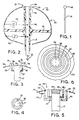
- a conductive curved surface as seen in Figure 1 typically a sphere 18, of a given radius is placed on a grounded rod 19 of given height and dimensioned according to design algorithms to be presently discussed.
- the passive, spherical air terminal so designed and placed may optimize the minimization of corona until the median field rises to a level sufficient to cause a surface discharge in the form of a corona burst.
- the embedded streamers are subsequently encouraged to develop into propagating leaders in the absence of space charge in the immediate vicinity. This is an improvement on the corona-producing sharp rods in current practice.
- the invention shows that simple replacement of sharp rods by blunt rods cannot achieve optimum performance and that the algorithms to be discussed are needed to determine the physical parameters according to location on a structure.
- the air terminal is shown generally at 20 and comprises a central conductive earth rod 21 for lightning attachment and conveyance of the discharge current to ground as indicated at 22.
- a curved conductive surface 24 Surrounding the rod is a curved conductive surface 24 which is supported at its widest point by an installation spider 25 extending from insulation sleeve 26.
- the top of the curved surface is provided with a ring 28 which has an undercut inner edge 29 forming a relatively sharp edge 30 at the top, seen in Figure 3, which edge is concentric with the central conductor rod 21.
- the ring 28 forms an annular concentric air gap at the top of the air terminal shown generally at 32.
- the top of the conductive rod is at approximately the same elevation and has a blunt configuration formed into a slightly convex, shallow dome, or rounded conical top 34 provided with a relatively sharp horizontally projecting lip 35.
- a non-conducting ring or sleeve 36 Surrounding the top of the conductive rod is a non-conducting ring or sleeve 36 which is adjustably mounted on the central conducting earth rod as seen at 37.
- the very tip of the ring indicated at 38 is positioned just proud of the shortest spark track between the top of the central conductor and the ring 28.
- the tip of the annular non-conducting ring will project preferably from about 1 millimeters to about 2 millimeters above the shortest line of the spark or arc so that the spark must literally jump over the ring tip 38 as indicated at 39 and enter a stronger electric field.
- an impedance/resistance unit 42 connecting the outer curved surface electrode 24 to ground through the central rod 21.
- the purpose of this impedance/resistance unit is to prevent early arcing due to random ion collection in the period of a quasi-static field due to overhead storm presence.
- a trimming capacitor 43 Also connecting the outer curved surface electrode to ground through the central rod is a trimming capacitor 43 to assist in optimizing the triggering point.
- the illustrated shape of the curved surface electrode 24 is similar to an oblate/prolate spheroid with the portion below the insulation spider at the widest point being oblate and the portion above being prolate.
- the size including the diameter or radius may be substantial as hereinafter noted with the diameter being typically from 50 mm to > 1 meter (for very tall structures, there may be a need for diameters > 1 meter in order to meet the corona criterion).
- FIG. 5 there is illustrated a modified form of air terminal which includes the grounded central conducting rod 21 having the blunt top 34 and the annular lip 35.
- the curved surface electrode 24 is provided with the annular ring 28 providing a somewhat larger air gap seen generally at 44.
- the spark gap is provided with a second annular conductive ring shown generally at 45.
- the ring 45 is supported on insulation bracket 46 from the central rod 21 but is electrically connected to the curved surface through a series resistor 47.
- the ring 45 then becomes an arc time extension ring, and the combination of the capacitance between the surface 24 and the rod 21, supplemented by the capacitance 43 and the series resister 47, will form an RC discharge circuit to maintain the triggering arc for a longer duration.
- the preferred air terminals illustrated in Figures 2-6 have properties so that they can be positioned and have geometric shapes such that they produce no corona emissions in the quasi-static electric fields before approach of a down leader.
- the air terminals also sense the approach of the down leader and act in a manner to reduce further the risk of corona generation.
- the terminals recognize when the median field has sufficient strength to support up leader formation and its propagation and trigger the emission of a streamer discharge when such conditions are met.
- the air terminals enhance the immediate electric field in conjunction with streamer emission in order to ensure optimum propagation conditions. They require no batteries, charging systems, radiation or electronically active components.
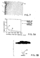
- FIG. 7 illustrates the electric field shown generally by the equipotential lines 50 surrounding an air terminal shown generally at 51.
- the curved or rounded surface at the top of the terminal is shown at 52, while the central earthed rod is shown at 53.
- the electric field concentration around the air terminal and about the rounded surface decays in intensity with distance as the field returns to the median or unperturbed value.
- Figure 8A illustrates the importance of this electric field decay with distance from the air terminals with very different field intensification factors.
- the line 55 represents the decay for a sharp rod such as a Franklin rod, which has a diameter of 6 mm and an overall height of 3 meters.
- the line 56 represents the decay for a blunt air terminal such as disclosed in Figures 1-6, which has a spherical upper surface of radius 0.5 m and an overall height of 2.5 meters.
- the respective field intensification factors are approximately 600 and 6.
- the decay distance to the ambient or median field is not a simple function of the intensification factor. It has a positive dependence on the height and radius of curvature but in different proportions, the height being the dominant factor. However, for a given height above ground, the electric field strength ahead of the terminal with the highest intensification (smallest radius) more quickly decays to the ambient field. Thus, any early formed streamer will find a rapidly decreasing field strength as it emerges from the air terminal tip. Such a streamer would not find sufficient energy in the field to progress into a leader (the amount of energy stored per unit volume in an electric field is in proportion to the square of the field strength).
- the sharp rod With further reference to Figure 8A, the sharp rod, with an intensification factor of about 600 to 1, will generate corona at a field strength of 3,000/600 kVm -1 , i.e. in an ambient field of only 5 kVm 1 .
- a space charge is being formed in those electric fields which exist before any down leader is initiated.
- Figure 8B the presence of positive ions 57 above a terminal 58 will act to reduce the strength of the normal negative field present below the thunder cloud shown.
- the effect of space charge in a large terminal-plane gap containing a uniform charge density at - 0.5 ⁇ C/m 3 is shown in Figure 8C.
- the electric field indicated by the curve 59 is almost completely neutralised at a distance of 4 meters from the terminal.
- the attachment process is a competition between several upward leaders. These competing leaders are not fully independent. Mutual repulsion or quenching of a leader by earlier propagating leaders is observable and may be predicted from finite element modeling. Accordingly, in the design of the system it is important not to ignore other nearby potential cites for upward leader initiation as hereinafter described. With the process of this invention, it is possible to define optimum conditions for lightning attachment and to assess these conditions for all competing points such as building corners and parapets. Thus, one or more air terminals of correct proportion can be located to provide superior performance over any nearby competing point.
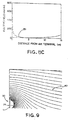
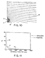
- Figure 9 illustrates the equipotential lines 60 of the electric field distribution around the terminal 20 under the static conditions where all of the elements are effectively grounded.
- FIG 10 there is illustrated a typical electric field observed by a ground point below a descending down leader.
- the electric field lines of equipotential are shown at 62.
- the natural electric field increase due to the approaching down leader is illustrated in the graph of Figure 11.
- the capacitive coupling between the floating surface 24 and the down leader charge, plus the restriction placed on the flow of displacement currents through the impedance/resistance 42 means that the surface of the curved surface electrode 24 will rise in voltage, or float upwardly in voltage.
- Figure 10 illustrates the equipotentials around an air terminal of the invention with a grounded rod and a floating curved surface electrode, elevated in potential due to the capacitive coupling to an approaching down leader.
- FIG 11 there is illustrated the field reduction with distance for the grounded and floating conditions described in connection with Figures 10 and 11. It is to be noted that within 100 millimeters there is a stronger field for the floating surface electrode illustrated at 64, but thereafter the field reduces to prevent any streamer growth. Conversely, the electric field at the surface 24 will always be lower in the floating state.
- the floating curve 64 crosses the grounded curve 66 at 67 which is within the first 100 millimeters from the tip.
- the field above the terminal is noticeably less than would be found in a grounded state under the same median field conditions. The raising of the potential of the curved surface therefore acts to reduce the chance of extensive corona formation during the down leader approach.
- the sparkover creates three key benefits, the first being to create free electrons at the point of highest electric field strength. Secondly it will assist electronic acceleration through the process of photo ionization, and finally the spark itself is a conductor, and in discharging the conductive surface 24, acts to ground that surface through to the central rod. This shifts the air terminal from one curve to the other as seen in Figure 11, and results in an immediate increase in the near field. In this manner, the conditions are then ideal to initiate and propagate an up leader.
- the ideal parameters of the air terminal of the present invention are determined primarily through two means: (A) computer modelling of electric fields using 2D and 3D finite element analysis, and (B) laboratory tests using a monotonically increasing or "concave" field which simulates the natural lightning strike.
- Method (A) is used to determine the correct height and curvature of the floating conductive surface and method B is used to determine the correct area of the surface and the size of the triggering air gap.
- the objective of both methods, in combination, is to create a trigger at a time when both the rate of rise of electric field and the median electric field are simulating the ideal propagation conditions as would be found in nature.
- the concave curve 70 of the required electric field is seen in Figure 12.
- the curve 70 is obtained by the generator shown schematically in Figure 13 as hereinafter described.
- the generator illustrated is capable of precisely simulating the electric field due to a lightning down leader, even including the well known steps or pauses as the leader progresses toward its point of attachment near the ground.
- the steps or pauses, smoothed out, are illustrated by the points 71.
- a Marx generator has been used for laboratory studies, but for this purpose a Marx generator is unsuitable since the wave form is the antithesis of the natural wave form.
- a trigger discharge can occur too early and leave a residual space charge to act against future streamer emission.
- a generator must be employed which in effect duplicates the monotonically increasing field which simulates nature as seen in Figure 12. Such a generator is shown in Figure 13.
- FIG. 13 there is illustrated a high voltage generator shown generally at 72.
- a computer 73 is installed with a high speed digital I/O card unit 74 which is used to output a 10-bit data word which is a pulse width modulated (PWM) representation of the rate of rise of a point on the desired wave form.
- PWM pulse width modulated
- the PWM frequency is 100 kHz and the data rate is 2 MHZ. This enables a PWM resolution of about 5%.
- it allows delays indicated at 75 to be inserted between each bit in the data stream in 5% steps in order to create a ripple effect increasing the slope between the points 71.
- Each delayed bit of output data is passed through opto-driver 76 to into one of ten opto-driven cables shown and then passed into an isolated switched-mode power supply (SMPS) with its own floating DC power supply, shown generally at 76.
- SMPS switched-mode power supply
- the fiber optic signals are converted back to electrical form inside each SMPS.
- the output stage of the generator uses transformers shown generally at 78 configured in a flyback topology to eliminate the need for output inductors.
- transformer primary winding switches 79 When the transformer primary winding switches 79 are activated by the amplified SMPS outputs, the primary side of each transformer acts as an inductor due to the blocking action of the output diode 80. When the switches are deactivated, the voltage reverses, and the inductive energy stored in the primary is released through the secondary winding. The output diode 80 then acts so that a negative voltage appears on each output.
- test waveform can be changed from concave, to linear, to convex in a relatively short period of time (on the order of minutes) so that empirical corrections for variations in temperature, pressure and humidity are not needed.
- the wave shapes can be stored and recalled at any time to repeat a test.
- the air terminals are tested in laboratory rigs using an overhead screen and can accordingly simulate natural lightning strikes on air terminals from various elevations and azimuth with the near and median fields being determined.
- a person skilled in the art may produce a field strength across the gap between the air terminal of the type illustrated and a test electrode which will be equal to the leader progression field, and simultaneously achieve a field rate of rise to match that of nature.
- the size of the annular spark gap 32 may then be set according to the surface area (capacitance) of the floating surface and the value of the surface to rod capacitance 42.
- FIG 14 A typical result is shown in Figure 14 where an air terminal 82 is placed away from a competing parapet 83 on a rectangular structure 84.
- the median field may be the optimum for sustained leader propagation, such as 500 kV/m and the terminal height and radius adjusted to meet the ideal streamer launch parameters.
- the near fields of the parapet 83 may be computed to find whether they exceed the optimum, and in which case, the terminal should be moved closer to the parapet to regain dominance.
- the illustrated plot of equipotentials around the structure 84 in the yz plane of the 3D model is for a vertically descending leader as indicated by the arrow 85.
- the plot of equipotentials around the structure is with the down leader approaching obliquely from the right as seen by the arrow 86.
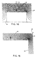
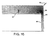
- FIG 16 there is shown another method where the equipotentials of the electric field around a structure 84 are determined, and in addition to the air terminal 82 there is provided an air terminal 88 on the parapet 83.
- the equipotentials are shown with an obliquely approaching down leader illustrated at 90.
- the air terminal is placed near a corner parapet with suitable height and radius to be an ideal attachment point for the obliquely approaching lightning down leader.
- the height projecting above the structure may be from about 1 meter to 6 meters or even higher.
- the size or curvature of the curved surface electrode may vary from about 50 mm in diameter to in excess of 1.5 meters in diameter.
- a preferred range is from about .5 meters to about 1 meter in diameter.
- the distance to the median field for these configurations is in the range 0.5 to 10 meters.
- an air terminal is provided with a curved surface electrode acting dynamically to minimize and further reduce corona during the close approach of a down leader. This is achieved by allowing the curved surface to float upwardly in voltage by use of a capacitive coupling to the approaching leader. The raising of the voltage in the same polarity as the leader acts to reduce, on average, the electric field in the vicinity of the air terminal. This acts to eliminate or substantially reduce corona in the dynamic phase of leader approach.
- a flashover or spark point is achieved between the curved surface and the main central earthed electrode, there are provided free electrons in avalanche mode, and the curved surface is simultaneously grounded through the arc.
- the grounding causes an instant increase in the electric field above the terminal at a time when there is virtually no space charge effect.
- Streamer formation is enhanced by the liberation of free electrons, the photoionization created by the arc, and the instant increase in the electric fields ahead of the streamer.
- the E field is intensified so as to have a field strength sufficient to cause a corona and on-going development into a streamer without the impediment of an intervening space charge.
- the air terminal is designed so that a streamer is only launched when both the near field and the median field strength, within a few meters of the terminal, are sufficiently strong to convert an initiating streamer into a propagating leader.
- the height and curvature of the terminal determines the E field intensification factor, and up leader conversion is assured, and the process is enhanced by propagation into an electric field devoid of distortions due to corona emissions in the form of space charges.
- the invention also includes a method to simulate natural lightning strike conditions and control not only the position of the lightning ground attachment, but also the ideal air terminal parameters to achieve the proper initiation of the streamer and up leader conversion.
- the system recognizes that there may be other structural points competing to be first launched leader and compares all points on approach of down leaders using a computer analysis involving three dimensional computer finite element modeling.
- the overall system differentiates from the industry generic term of "early streamer emission” in that such terminals become active far too early and produce space charge from failed attempts to launch streamers.
- This invention more properly relates to the term “controlled streamer emission” by holding off streamers until leader conversion and propagation conditions are optimized.
Landscapes
- Elimination Of Static Electricity (AREA)
Applications Claiming Priority (2)
| Application Number | Priority Date | Filing Date | Title |
|---|---|---|---|
| US9428098P | 1998-07-27 | 1998-07-27 | |
| US94280P | 1998-07-27 |
Publications (2)
| Publication Number | Publication Date |
|---|---|
| EP0977336A2 true EP0977336A2 (de) | 2000-02-02 |
| EP0977336A3 EP0977336A3 (de) | 2000-11-15 |
Family
ID=22244217
Family Applications (1)
| Application Number | Title | Priority Date | Filing Date |
|---|---|---|---|
| EP99114242A Withdrawn EP0977336A3 (de) | 1998-07-27 | 1999-07-27 | Luft-blitzschutzanlage und Design- und Herstellungsverfahren |
Country Status (5)
| Country | Link |
|---|---|
| US (1) | US6320119B1 (de) |
| EP (1) | EP0977336A3 (de) |
| AU (1) | AU753280B2 (de) |
| ID (1) | ID24540A (de) |
| MY (1) | MY117053A (de) |
Cited By (4)
| Publication number | Priority date | Publication date | Assignee | Title |
|---|---|---|---|---|
| WO2007062659A1 (en) * | 2005-12-02 | 2007-06-07 | Lm Glasfiber A/S | Lightning protection system for a wind turbine blade |
| FR2953337A1 (fr) * | 2009-11-30 | 2011-06-03 | France Paratonnerres | Paratonnerre a fonctionnement regule |
| RU2645730C2 (ru) * | 2016-02-05 | 2018-02-28 | Ордена трудового Красного Знамени федеральное государственное бюджетное образовательное учреждение высшего образования "Московский технический университет связи и информатики" (МТУСИ) | Способ защиты оптических кабелей связи от грозовых разрядов |
| EP3531803A4 (de) * | 2016-10-21 | 2020-07-01 | Lightning Suppression Systems Co., Ltd. | Blitzschlagunterdrückende blitzschutzvorrichtung und blitzableiter |
Families Citing this family (21)
| Publication number | Priority date | Publication date | Assignee | Title |
|---|---|---|---|---|
| BR0103416A (pt) * | 2001-04-23 | 2003-01-14 | Furnas Centrais Eletricas S A | Dispositivo para instalação de esferas de sinalização em cabos pára-raios de linhas de transmissão, e métodos para instalação de esferas de sinalização em cabos pára-raios de linhas de transmissão utilizando referido dispositivo |
| USD478294S1 (en) | 2002-08-02 | 2003-08-12 | Alltec Corporation | Lightning dissipation assembly |
| USD478525S1 (en) | 2002-08-16 | 2003-08-19 | Alltec Corporation | Point discharge dissipation terminal |
| USD478295S1 (en) | 2002-08-16 | 2003-08-12 | Alltec Corporation | High dissipation discharge terminal |
| KR100433011B1 (ko) * | 2003-06-25 | 2004-05-28 | 정용기 | 쌍극자 멀티 공간전하 분산형 피뢰장치 |
| AU2004235650B2 (en) * | 2003-07-01 | 2008-07-10 | Erico International Corporation | Lightning Protection Device and Method |
| US7265961B2 (en) * | 2003-07-01 | 2007-09-04 | Erico International Corporation | Lightning protection device and method |
| AU2004235649B2 (en) * | 2003-07-01 | 2008-07-10 | Erico International Corporation | Lightning Protection Device and Method |
| FR2874757B1 (fr) * | 2004-09-02 | 2006-11-10 | Helita Soc Par Actions Simplif | Methode d'evaluation de l'etendue de la zone de protection conferee par un dispositif de capture de coup de foudre |
| EP1958306A4 (de) * | 2005-11-23 | 2016-06-08 | Farouk A M Rizk | Blitzschutzeinrichtung: nass-/trocken-streamer-inhibitor auf glühbasis |
| EP2005549A1 (de) * | 2006-03-03 | 2008-12-24 | Farouk A. M. Rizk | Schutzeinrichtung: spitzenunterdrückungsleiter |
| WO2007137413A1 (en) * | 2006-05-26 | 2007-12-06 | Rizk Farouk A M | Flashover protection device and method: wet/dry glow-based streamer inhibitor |
| WO2008046186A1 (en) * | 2006-10-04 | 2008-04-24 | Rizk Farouk A M | Lightning protection device for a wind turbine blade: wet/dry glow-based streamer inhibitor |
| CN101611655B (zh) * | 2006-10-24 | 2013-01-02 | 法鲁克·A·M·里兹克 | 雷闪防护装置:湿/干场敏感避雷针 |
| USD670591S1 (en) | 2010-06-25 | 2012-11-13 | Alltec Corporation | Early streamer emission terminal |
| US8232472B1 (en) | 2010-06-25 | 2012-07-31 | Alltec Corporation | Early streamer emission terminal |
| KR101496979B1 (ko) * | 2013-11-07 | 2015-03-02 | 한국산업은행 | 쌍극자 피뢰장치 |
| KR101491414B1 (ko) * | 2014-06-13 | 2015-02-06 | 정용기 | 능동형 낙뢰 수뢰장치 |
| US11251595B2 (en) | 2018-07-03 | 2022-02-15 | Erico International Corporation | Lightning protection system and method |
| CN112837417B (zh) * | 2021-03-02 | 2023-06-16 | 华南理工大学 | 一种基于改进随机模型的三维空间雷电先导仿真方法 |
| RU207209U1 (ru) * | 2021-07-09 | 2021-10-18 | Общество с ограниченной ответственностью "Электра" | Молниеприемник с опережающей эмиссией стримера с расширенными функциональными возможностями |
Family Cites Families (29)
| Publication number | Priority date | Publication date | Assignee | Title |
|---|---|---|---|---|
| US175933A (en) | 1876-04-11 | Improvement in lightning-rods | ||
| US492512A (en) | 1893-02-28 | Lightning-rod ball | ||
| US110778A (en) | 1871-01-03 | Improvement in lightning-rods | ||
| US4807A (en) | 1846-10-07 | Improvement | ||
| US356531A (en) | 1887-01-25 | Lightning-rod | ||
| US369915A (en) | 1887-09-13 | Lightning-conductor | ||
| US1164757A (en) | 1915-03-20 | 1915-12-21 | Schweitzer And Conrad | Lightning-arrester. |
| US1477304A (en) | 1919-03-07 | 1923-12-11 | Westinghouse Electric & Mfg Co | Protective device |
| US2025338A (en) | 1931-09-05 | 1935-12-24 | Capart Gustave Paul | Lightning rod assembly |
| US2128408A (en) | 1935-08-12 | 1938-08-30 | Internat Holding Radial | Radioactive protective apparatus, such as lightning arresters and hail protectors |
| US2644026A (en) | 1950-04-24 | 1953-06-30 | Helita Soc | Radioactive lightining protector with accelerating elements |
| US2815395A (en) | 1952-03-26 | 1957-12-03 | United States Radium Corp | Radioactive lightning protector |
| BE731528A (de) | 1969-04-15 | 1969-09-15 | ||
| CH521677A (fr) | 1971-03-18 | 1972-04-15 | En Froide Internat S A | Installation de protection antifoudre pour bâtiments et bateaux |
| FR2343342A1 (fr) | 1976-02-18 | 1977-09-30 | Helita | Dispositif de raccordement entre une descente de paratonnerre et un conducteur de mise a la terre |
| FR2343338A1 (fr) | 1976-03-01 | 1977-09-30 | Helita | Dispositif de connexion pour prise de terre |
| DE3260592D1 (en) | 1981-03-06 | 1984-09-27 | Helita Societe Francaise | Ionizing lightning protector with corona effect |
| US4480146A (en) | 1982-06-03 | 1984-10-30 | Energie Froide International Sa | Lightning protector assembly |
| FR2543370B1 (fr) | 1983-03-25 | 1986-03-07 | Commissariat Energie Atomique | Paratonnerre a dispositif piezo-electrique d'amorcage de l'effet corona. |
| ES526264A0 (es) | 1983-09-19 | 1984-07-01 | Illa Arnau Angel | Perfeccionamientos en la construccion de pararrayos |
| FR2553236B1 (fr) | 1983-10-07 | 1986-01-10 | Pierson Alexandre | Dispositif auto-alimente de protection contre la foudre |
| GR73444B (de) | 1984-02-01 | 1984-02-28 | Kokkinos Dimitrios | |
| US4540844A (en) | 1984-03-28 | 1985-09-10 | Societe Francaise Helita | Electrical ionizing devices for lightning protection |
| ATE87141T1 (de) * | 1985-12-19 | 1993-04-15 | John Richard Gumley | Blitzableiter. |
| MY100406A (en) | 1985-12-19 | 1990-09-29 | Erico Lightning Tech Pty Ltd | Lightning conductor |
| FR2620581B1 (fr) | 1987-09-16 | 1990-01-19 | Chassain Roger | Installation de paratonnerre perfectionnee |
| FR2624319B1 (fr) | 1987-12-07 | 1990-05-04 | Lewiner Jacques | Dispositifs de protection contre la foudre a emission ionique |
| FR2697379B1 (fr) | 1992-10-28 | 1995-01-13 | Helita Sa | Paratonnerre à dispositif d'amorçage à décharge électrique glissante le long d'un diélectrique. |
| AUPO079196A0 (en) * | 1996-07-02 | 1996-07-25 | Global Lightning Technologies Pty. Ltd. | Improved lightning conductor and method |
-
1999
- 1999-07-26 ID IDP990705D patent/ID24540A/id unknown
- 1999-07-26 US US09/361,374 patent/US6320119B1/en not_active Expired - Lifetime
- 1999-07-26 AU AU41137/99A patent/AU753280B2/en not_active Expired
- 1999-07-27 EP EP99114242A patent/EP0977336A3/de not_active Withdrawn
- 1999-07-27 MY MYPI99003154A patent/MY117053A/en unknown
Cited By (7)
| Publication number | Priority date | Publication date | Assignee | Title |
|---|---|---|---|---|
| WO2007062659A1 (en) * | 2005-12-02 | 2007-06-07 | Lm Glasfiber A/S | Lightning protection system for a wind turbine blade |
| US8177509B2 (en) | 2005-12-02 | 2012-05-15 | Lm Glasfiber A/S | Lightning protection system for a wind turbine blade |
| FR2953337A1 (fr) * | 2009-11-30 | 2011-06-03 | France Paratonnerres | Paratonnerre a fonctionnement regule |
| WO2011067481A2 (fr) | 2009-11-30 | 2011-06-09 | France Paratonnerres | Paratonnerre a fonctionnement regule |
| WO2011067481A3 (fr) * | 2009-11-30 | 2011-07-28 | France Paratonnerres | Paratonnerre a fonctionnement regule |
| RU2645730C2 (ru) * | 2016-02-05 | 2018-02-28 | Ордена трудового Красного Знамени федеральное государственное бюджетное образовательное учреждение высшего образования "Московский технический университет связи и информатики" (МТУСИ) | Способ защиты оптических кабелей связи от грозовых разрядов |
| EP3531803A4 (de) * | 2016-10-21 | 2020-07-01 | Lightning Suppression Systems Co., Ltd. | Blitzschlagunterdrückende blitzschutzvorrichtung und blitzableiter |
Also Published As
| Publication number | Publication date |
|---|---|
| AU753280B2 (en) | 2002-10-17 |
| EP0977336A3 (de) | 2000-11-15 |
| ID24540A (id) | 2000-07-27 |
| MY117053A (en) | 2004-04-30 |
| US6320119B1 (en) | 2001-11-20 |
| AU4113799A (en) | 2000-02-17 |
Similar Documents
| Publication | Publication Date | Title |
|---|---|---|
| US6320119B1 (en) | Lightning air terminals and method of design and application | |
| AU2020200901B2 (en) | Passive compound strong-ionization discharging plasma lightning rejection device | |
| Heidler et al. | Parameters of lightning current given in IEC 62305-background, experience and outlook | |
| CN101611655B (zh) | 雷闪防护装置:湿/干场敏感避雷针 | |
| US7265961B2 (en) | Lightning protection device and method | |
| JP2519433B2 (ja) | 避雷方法及び避雷装置 | |
| AU684051B2 (en) | A lightning conductor having an initiator device using a sliding electrical discharge along a dielectric | |
| WO2023202172A1 (zh) | 一种雷电拦截装置 | |
| CN105118588A (zh) | 一种500kV输电线路复合绝缘子并联间隙的设计方法 | |
| CN110768107A (zh) | 一种非引雷入地的避雷装置及方法 | |
| CN114759435B (zh) | 一种雷电抑制装置 | |
| Yamamoto et al. | An experimental study of lightning overvoltages in wind turbine generation systems using a reduced‐size model | |
| KR100463438B1 (ko) | 다량의 이온을 발생시키는 스트리머 방전형 피뢰침 | |
| CN112117746B (zh) | 一种消除档距中央闪络和工频绝缘强度损失的方法及系统 | |
| Mackerras et al. | Review of claimed enhanced lightning protection of buildings by early streamer emission air terminals | |
| CN201741985U (zh) | 一种预放电避雷装置 | |
| Vance et al. | Differences between lightning and nuclear electromagnetic pulse interactions | |
| CN212571700U (zh) | 一种提前放电接闪器 | |
| CN217087138U (zh) | 一种雷电拦截装置 | |
| CN217134883U (zh) | 一种雷电拦截装置 | |
| Morrow et al. | The stepped nature of lightning, and the upward connecting streamer | |
| CN205790944U (zh) | 压控感应场致等离子发射式避雷装置 | |
| RU226413U1 (ru) | Молниеприемник с опережающей эмиссией стримера | |
| RU2856338C1 (ru) | Средство защиты от прямого удара молнии | |
| Qiu et al. | Lightning strike protection performance research of early streamer emission terminal based on contrastive discharge test |
Legal Events
| Date | Code | Title | Description |
|---|---|---|---|
| PUAI | Public reference made under article 153(3) epc to a published international application that has entered the european phase |
Free format text: ORIGINAL CODE: 0009012 |
|
| AK | Designated contracting states |
Kind code of ref document: A2 Designated state(s): AT BE CH CY DE DK ES FI FR GB GR IE IT LI LU MC NL PT SE |
|
| AX | Request for extension of the european patent |
Free format text: AL;LT;LV;MK;RO;SI |
|
| PUAL | Search report despatched |
Free format text: ORIGINAL CODE: 0009013 |
|
| AK | Designated contracting states |
Kind code of ref document: A3 Designated state(s): AT BE CH CY DE DK ES FI FR GB GR IE IT LI LU MC NL PT SE |
|
| AX | Request for extension of the european patent |
Free format text: AL;LT;LV;MK;RO;SI |
|
| 17P | Request for examination filed |
Effective date: 20010507 |
|
| AKX | Designation fees paid |
Free format text: AT BE CH CY DE DK ES FI FR GB GR IE IT LI LU MC NL PT SE |
|
| 17Q | First examination report despatched |
Effective date: 20041103 |
|
| GRAP | Despatch of communication of intention to grant a patent |
Free format text: ORIGINAL CODE: EPIDOSNIGR1 |
|
| RTI1 | Title (correction) |
Free format text: LIGHTNING AIR TERMINAL |
|
| STAA | Information on the status of an ep patent application or granted ep patent |
Free format text: STATUS: THE APPLICATION IS DEEMED TO BE WITHDRAWN |
|
| 18D | Application deemed to be withdrawn |
Effective date: 20091103 |