EP0977337A2 - Circuit de mesure et de limitation des courants dans des convertisseurs pour l'alimentation des moteurs - Google Patents
Circuit de mesure et de limitation des courants dans des convertisseurs pour l'alimentation des moteurs Download PDFInfo
- Publication number
- EP0977337A2 EP0977337A2 EP99113966A EP99113966A EP0977337A2 EP 0977337 A2 EP0977337 A2 EP 0977337A2 EP 99113966 A EP99113966 A EP 99113966A EP 99113966 A EP99113966 A EP 99113966A EP 0977337 A2 EP0977337 A2 EP 0977337A2
- Authority
- EP
- European Patent Office
- Prior art keywords
- current
- capacitor
- circuit
- converter
- intermediate circuit
- Prior art date
- Legal status (The legal status is an assumption and is not a legal conclusion. Google has not performed a legal analysis and makes no representation as to the accuracy of the status listed.)
- Granted
Links
Images

Classifications
-
- H—ELECTRICITY
- H02—GENERATION; CONVERSION OR DISTRIBUTION OF ELECTRIC POWER
- H02M—APPARATUS FOR CONVERSION BETWEEN AC AND AC, BETWEEN AC AND DC, OR BETWEEN DC AND DC, AND FOR USE WITH MAINS OR SIMILAR POWER SUPPLY SYSTEMS; CONVERSION OF DC OR AC INPUT POWER INTO SURGE OUTPUT POWER; CONTROL OR REGULATION THEREOF
- H02M1/00—Details of apparatus for conversion
- H02M1/42—Circuits or arrangements for compensating for or adjusting power factor in converters or inverters
- H02M1/4208—Arrangements for improving power factor of AC input
- H02M1/4225—Arrangements for improving power factor of AC input using a non-isolated boost converter
-
- H—ELECTRICITY
- H02—GENERATION; CONVERSION OR DISTRIBUTION OF ELECTRIC POWER
- H02M—APPARATUS FOR CONVERSION BETWEEN AC AND AC, BETWEEN AC AND DC, OR BETWEEN DC AND DC, AND FOR USE WITH MAINS OR SIMILAR POWER SUPPLY SYSTEMS; CONVERSION OF DC OR AC INPUT POWER INTO SURGE OUTPUT POWER; CONTROL OR REGULATION THEREOF
- H02M5/00—Conversion of AC power input into AC power output, e.g. for change of voltage, for change of frequency, for change of number of phases
- H02M5/40—Conversion of AC power input into AC power output, e.g. for change of voltage, for change of frequency, for change of number of phases with intermediate conversion into DC
- H02M5/42—Conversion of AC power input into AC power output, e.g. for change of voltage, for change of frequency, for change of number of phases with intermediate conversion into DC by static converters
- H02M5/44—Conversion of AC power input into AC power output, e.g. for change of voltage, for change of frequency, for change of number of phases with intermediate conversion into DC by static converters using discharge tubes or semiconductor devices to convert the intermediate DC into AC
- H02M5/453—Conversion of AC power input into AC power output, e.g. for change of voltage, for change of frequency, for change of number of phases with intermediate conversion into DC by static converters using discharge tubes or semiconductor devices to convert the intermediate DC into AC using devices of a triode or transistor type requiring continuous application of a control signal
- H02M5/458—Conversion of AC power input into AC power output, e.g. for change of voltage, for change of frequency, for change of number of phases with intermediate conversion into DC by static converters using discharge tubes or semiconductor devices to convert the intermediate DC into AC using devices of a triode or transistor type requiring continuous application of a control signal using semiconductor devices only
-
- H—ELECTRICITY
- H02—GENERATION; CONVERSION OR DISTRIBUTION OF ELECTRIC POWER
- H02P—CONTROL OR REGULATION OF ELECTRIC MOTORS, ELECTRIC GENERATORS OR DYNAMO-ELECTRIC CONVERTERS; CONTROLLING TRANSFORMERS, REACTORS OR CHOKE COILS
- H02P21/00—Arrangements or methods for the control of electric machines by vector control, e.g. by control of field orientation
- H02P21/22—Current control, e.g. using a current control loop
-
- G—PHYSICS
- G01—MEASURING; TESTING
- G01R—MEASURING ELECTRIC VARIABLES; MEASURING MAGNETIC VARIABLES
- G01R19/00—Arrangements for measuring currents or voltages or for indicating presence or sign thereof
- G01R19/0092—Measuring current only
-
- H—ELECTRICITY
- H02—GENERATION; CONVERSION OR DISTRIBUTION OF ELECTRIC POWER
- H02M—APPARATUS FOR CONVERSION BETWEEN AC AND AC, BETWEEN AC AND DC, OR BETWEEN DC AND DC, AND FOR USE WITH MAINS OR SIMILAR POWER SUPPLY SYSTEMS; CONVERSION OF DC OR AC INPUT POWER INTO SURGE OUTPUT POWER; CONTROL OR REGULATION THEREOF
- H02M1/00—Details of apparatus for conversion
- H02M1/0003—Details of control, feedback or regulation circuits
- H02M1/0009—Devices or circuits for detecting current in a converter
-
- H—ELECTRICITY
- H02—GENERATION; CONVERSION OR DISTRIBUTION OF ELECTRIC POWER
- H02M—APPARATUS FOR CONVERSION BETWEEN AC AND AC, BETWEEN AC AND DC, OR BETWEEN DC AND DC, AND FOR USE WITH MAINS OR SIMILAR POWER SUPPLY SYSTEMS; CONVERSION OF DC OR AC INPUT POWER INTO SURGE OUTPUT POWER; CONTROL OR REGULATION THEREOF
- H02M1/00—Details of apparatus for conversion
- H02M1/0067—Converter structures employing plural converter units, other than for parallel operation of the units on a single load
- H02M1/007—Plural converter units in cascade
-
- Y—GENERAL TAGGING OF NEW TECHNOLOGICAL DEVELOPMENTS; GENERAL TAGGING OF CROSS-SECTIONAL TECHNOLOGIES SPANNING OVER SEVERAL SECTIONS OF THE IPC; TECHNICAL SUBJECTS COVERED BY FORMER USPC CROSS-REFERENCE ART COLLECTIONS [XRACs] AND DIGESTS
- Y02—TECHNOLOGIES OR APPLICATIONS FOR MITIGATION OR ADAPTATION AGAINST CLIMATE CHANGE
- Y02B—CLIMATE CHANGE MITIGATION TECHNOLOGIES RELATED TO BUILDINGS, e.g. HOUSING, HOUSE APPLIANCES OR RELATED END-USER APPLICATIONS
- Y02B70/00—Technologies for an efficient end-user side electric power management and consumption
- Y02B70/10—Technologies improving the efficiency by using switched-mode power supplies [SMPS], i.e. efficient power electronics conversion e.g. power factor correction or reduction of losses in power supplies or efficient standby modes
Definitions
- the present invention relates to a circuit arrangement based thereon Method for measuring the currents from a voltage intermediate circuit powered converter for controlling motors with a measuring device for current measurement, both the phase currents of the motor and the current consumption can be measured from the network according to claim 1, as well as a Circuit arrangement for inrush current limitation according to claim 2.
- a circuit arrangement for active power factor correction (PFC), i.e. to Controlled current consumption from the network according to the prior art is e.g. on Page 49, picture 1, in issue 23/1996 of the magazine "ELEKTRONIK", Franzis-Verlag, released.
- the corresponding current measuring resistor for measuring the mains current consumption is located there in the mains cable.
- Circuit arrangements for inrush current limitation are e.g. in the data book: thermistor, Siemens Matsushita Components, 1996, page 36, Figure 10 or in the Thomson-CSF LCC data book, 1994, page 28, Figure 16 refer to.
- NTC temperature-dependent Resistor
- a conventional circuit arrangement for measuring the phase currents a 6-pulse converter fed three-phase motor which e.g. from the publications listed below is known, is exemplary in the figures 5 and 6.
- the simplified topology is shown schematically in FIG a converter 5 fed from a voltage intermediate circuit 4 for supply of a three-phase motor 1 shown.
- the reloading device for the intermediate circuit capacitor 10 of the voltage intermediate circuit 4 is, for example from a rectifier bridge 3 connected to the low-voltage network 2 6-pulse converter 5 has three upper switching means 6a, 7a, 8a and three Switching means 6b, 7b, 8b, which is implemented, for example, by power transistors are.
- the switching means 6-8 form three switching means half bridges 6a-6b, 7a-7b and 8a-8b, which are each inversely controlled, so that - if neglected the switching dead times - one from each half-bridge at any time Switching means open and the corresponding other switching means is closed.
- a means 9 is optionally between the voltage intermediate circuit 4 and the converter 5 or 9 'connected to the current measurement, which is the measurement of the converter current Idc or alternatively Idc 'is used in the voltage intermediate circuit 4. According to the in FIG. 5 In the illustrated prior art, the current is measured in the voltage intermediate circuit 4 in a current path in which only the converter current Idc, Idc 'flows.
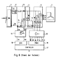
- FIG 6 is the complete topology of the conventional shown in Figure 5 Electronics illustrated.
- the rectifier bridge 3 to rectify the AC voltage when supplying the electronics the low-voltage network 2 shown.
- the positive output of the rectifier bridge 3 is connected to an inrush current limiter 11 which, for example, consists of a NTC resistor 12 to limit the current consumption of the connected Electronics when connected to the mains when the intermediate circuit capacitor 10 is discharged.
- a device 13 for active is also connected to the rectifier bridge 3 Control of current consumption on network 2 for power factor correction (PFC) connected in the topology of a step-up converter.
- the step-up converter shown 13 also has a means 14 for measuring the mains current in the form of a Measuring resistance.
- this measuring resistor 14 cannot be chosen as large be that the inrush current limiter 11 could be omitted because of the power loss when using a suitable fixed resistor in the power supply line would be great.
- the step-up converter 13 is followed by the one already explained with reference to FIG. 5
- Voltage intermediate circuit 4 with, for example, a high-voltage electrolytic capacitor 10 on.
- the current measuring means 9 is in a current path of the voltage intermediate circuit 4 arranged in which only the converter current Idc flows.
- the voltage intermediate circuit 4 feeds the converter 5, which acts as a 6-pulse bridge is designed for the three-phase motor 1.
- switching means 6-8 of the converter 5 are according to the prior art, for example, power transistors such IGBTs, used with anti-parallel connected freewheeling diodes.
- An analog driver module 15 amplifies the two measuring resistors 9 and 14 tapped measurement signals so that the measurement signals Im (mains current) and Idc (Converter current) by an analog / digital converter 16 of a control device 17, such as a microcontroller, evaluated with sufficient resolution can be.
- the microcontroller 17 controls and regulates both Motor 1 via the switching means 6-8 of the converter 5 as well as the current consumption from the low-voltage network 2 via the switching means 18 of the step-up converter 13.
- the switching means 6-8 and 18 are used, for example, by a PWM (pulse width modulation) unit 19 with the help of a digital power driver module 20 controlled.
- a device for measurement to propose the currents of a motor fed from a converter which not only enables the measurement of the motor currents, but also with that Mains current consumption can be measured and limited.
- the current measuring means for measuring the current Icap in the capacitance of the voltage intermediate circuit simultaneously as an inrush current limiter discharged intermediate circuit capacitor acts when the current measuring means is in shape an electrical resistance is formed. This makes it possible to click on one additional resistance for inrush current limitation at the output of the rectifier bridge to renounce.
- the resistance to the inrush current limitation is not in the mains supply, but is in series with the DC link capacitor where the effective Current load is typically lower by a factor of 2, which reduces the power loss at the inrush current limiter with the same resistance value approximately to 1 ⁇ 4 reduced compared to the conventional arrangement, for example instead of a more expensive temperature-dependent resistor uses a fixed resistor become.
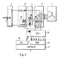
- Figure 1 is first a simplified circuit arrangement for the invention Measurement of the phase currents Iu, Iv, Iw of a three-phase motor 1 shown which is operated by a 6-pulse converter 5.
- the converter 5 in turn is fed from a voltage intermediate circuit 4, which is essentially an intermediate circuit capacitor 10, preferably a high-voltage electrolytic capacitor, is constructed.
- the reloading device for the intermediate circuit capacitor 10 of the voltage intermediate circuit 4 consists of a low-voltage network 2 connected rectifier bridge 3 known type.
- the 6-pulse converter 5 has three upper switching means 6a, 7a, 8a and three below Switching means 6b, 7b and 8b, which are preferably provided by power transistors, such as IGBTs, realized with freewheeling diodes connected in anti-parallel are.
- the switching means 6-8 are three switching means half bridges 6a-6b, 7a-7b and 8a-8b, which are each inversely controlled, i.e. if the top Switching means 6a, 7a, 8a is closed, is neglected in the Switching dead times that occur in practice - the corresponding lower switching means 6b, 7b and 8b opened and vice versa.
- a means 21 or 21 ' is used to measure the phase currents Iu, Iv, Iw of the motor 1. provided for current measurement, which is arranged in a current path in which exclusively the current Icap or Icap 'of the capacitance 10 of the voltage intermediate circuit 4 - hereinafter only briefly referred to capacitor current Icap - flows.
- the means 21, 21 'for measuring the current is preferably in series with the DC link capacitor 10 connected.
- a Means for actively controlling the current consumption from the low-voltage network 2 switched which is shown in the topology of a step-up converter 13.
- the step-up converter is used to correct the power factor (PFC) EMC regulations regarding harmonics.
- the step-up converter 13 has, connected in parallel with the intermediate circuit capacitor 10, a switching means 18 on which - like the switching means 6-8 of the converter 5 - does not come from one in FIG shown control device 17 is controlled to the current consumption of the circuit arrangement to control. In this case the current current Icap depends on DC link capacitor 10 also from the current switching state of the switching means 18.
- the step-up converter 13 does not comprise any current measuring means for measuring the mains current Im, since this mains current Im according to the invention also measured by measuring the current of the capacitor current Icap can be, as will be explained below.
- FIG. 1 The complete topology of the electronics for control according to the invention of a three-phase motor 1 is shown in FIG.
- the circuit arrangement has like the circuit arrangement of FIG. 2, active control of the current consumption from network 2 for power factor correction.
- the rectifier bridge assemblies 3, step-up converter 13, voltage intermediate circuit 4 and converter 5 correspond the assemblies already described above with reference to FIGS. 1 and 2, which is why a detailed description should be omitted here.
- the control device 17 controls and regulates both the motor 1 via the switching means 6-8 and the current consumption the low-voltage network 2 via the switching means 18.
- the microcontroller 17 can the measuring signal Icap of the measuring resistor 21 directly via its analog / digital converter 16 evaluate. To an analog driver stage for preamplification of the Measuring signals Icap can be omitted here, since the current load for the Measuring resistor 21 is lower in the circuit arrangement according to the invention than in the conventional circuit arrangement according to FIG. 6 (measuring resistor 14), and thus the resistance value of the measuring resistor 21 selected as large can be that the A / D converter 16 of the microcontroller 17 the measurement signal Icap can evaluate with sufficient resolution even without preamplification.
- Both the switching means 6-8 of the converter 5 and the switching means 18 of the Boost converter 13 are from the microcontroller 17 via a modulation unit 19 controlled by means of a digital power driver module 20.
- a modulation unit 19 becomes a PWM (Pulse Width Modulation) unit or alternatively a delta modulation unit is used.
- the switching means 6-8, 18 will generally the so-called natural PWM is used. In essence, this procedure the duty cycle of a square waveform of fixed frequency with magnitude modulated by a sine wave.
- the control of the Switching means synchronized, various possibilities being known for this. A detailed description of the modulation options can be found, for example in the above-mentioned publication by T.C. Green and B.W. Williams.
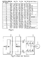
- power stage 20 can also be switched off immediately ( ⁇ stop) become. Different positive and negative overcurrents can be used Limit values must be defined. If the power level 20 is switched off in this way the motor terminals of motor 1 are preferably short-circuited automatically, as in the switching states 0, 7, 8 and 15 of the table explained below of Figure 4 is the case.
- the switching states of the switching means 6-8, 18 using a simple logic circuit from the seven control signals U +, U-, V +, V-, W +, W- and PFC of the PWM unit 19 can be identified. From the symmetry of the converter circuit 5 it follows that the capacitor current Icap, for example, in switching states 10 and 13 only from the phase current Iv or in the switching states 2 and 5 only from the phase current Iv and the Mains current Im depends.
- the A / D converter 16 detects synchronously with the current one Switching states of the switching means 6-8, 18, the current measurement signal Icap. By the Capacitor current Icap and at the same time the switching states of the switching means in The moment of the current measurement can be detected, the course of the phase currents Iu, Iv, Iw of the motor 1 and the mains current Im to be reconstructed.
- the switching states of the table in FIG. 4 are reduced to Switching states 0 to 7.
- the measurement of the instantaneous phase current Iu, Iv, Iw is then carried out by measuring the difference between the total current and the mains current Im + phase current Iu, Iv, Iw (switching states 1 to 6) and the mains current Im (Switching states 0 and 7).
Landscapes
- Engineering & Computer Science (AREA)
- Power Engineering (AREA)
- Control Of Multiple Motors (AREA)
- Inverter Devices (AREA)
- Rectifiers (AREA)
- Electric Propulsion And Braking For Vehicles (AREA)
- Control Of Ac Motors In General (AREA)
Applications Claiming Priority (2)
| Application Number | Priority Date | Filing Date | Title |
|---|---|---|---|
| DE19834315 | 1998-07-30 | ||
| DE19834315A DE19834315A1 (de) | 1998-07-30 | 1998-07-30 | Schaltungsanordnung zur Messung und Begrenzung von Strömen in Umrichtern zur Speisung von Motoren |
Publications (3)
| Publication Number | Publication Date |
|---|---|
| EP0977337A2 true EP0977337A2 (fr) | 2000-02-02 |
| EP0977337A3 EP0977337A3 (fr) | 2005-06-01 |
| EP0977337B1 EP0977337B1 (fr) | 2011-03-09 |
Family
ID=7875815
Family Applications (1)
| Application Number | Title | Priority Date | Filing Date |
|---|---|---|---|
| EP99113966A Expired - Lifetime EP0977337B1 (fr) | 1998-07-30 | 1999-07-17 | Circuit de mesure et de limitation des courants dans des convertisseurs pour l'alimentation des moteurs |
Country Status (3)
| Country | Link |
|---|---|
| EP (1) | EP0977337B1 (fr) |
| AT (1) | ATE501540T1 (fr) |
| DE (2) | DE19834315A1 (fr) |
Cited By (9)
| Publication number | Priority date | Publication date | Assignee | Title |
|---|---|---|---|---|
| WO2003038987A1 (fr) * | 2001-11-02 | 2003-05-08 | Leopold Kostal Gmbh & Co. Kg | Procede pour faire fonctionner un appareil de commande |
| EP1225452A3 (fr) * | 2001-01-19 | 2004-01-28 | Robert Bosch Gmbh | Procédé de mesure des courants des demi-ponts |
| EP1333570A3 (fr) * | 2002-01-31 | 2004-09-08 | Diehl AKO Stiftung & Co. KG | Procédé et circuit pour mésurer et limiter des courants |
| WO2008034515A1 (fr) * | 2006-09-22 | 2008-03-27 | Recaro Aircraft Seating Gmbh & Co. Kg | Dispositif d'alimentation en courant électrique à correction du facteur de puissance et limitation du courant (d'enclenchement) |
| US7804288B2 (en) | 2006-12-21 | 2010-09-28 | Vacon Oyj | Current measuring arrangement of a frequency converter |
| WO2012163645A3 (fr) * | 2011-05-30 | 2013-10-03 | Robert Bosch Gmbh | Procédé de détermination de courant dans une machine polyphasée |
| CN109546911A (zh) * | 2018-11-29 | 2019-03-29 | 宁波诺丁汉大学 | 基于混和脉宽调制技术的单电流传感器电机控制方法 |
| WO2019091996A1 (fr) * | 2017-11-08 | 2019-05-16 | Ebm-Papst Mulfingen Gmbh & Co. Kg | Réduction de capacité |
| CN114830269A (zh) * | 2019-11-05 | 2022-07-29 | 西门子股份公司 | 用于在电动机的矩形波电压的情况下进行电压均衡的装置 |
Families Citing this family (2)
| Publication number | Priority date | Publication date | Assignee | Title |
|---|---|---|---|---|
| DE102010015312A1 (de) * | 2010-04-17 | 2011-10-20 | Audi Ag | Hochvoltsystem für ein Kraftfahrzeug und Verfahren zur Diagnose eines Hochvoltsystems für ein Kraftfahrzeug |
| DE102011003897A1 (de) * | 2011-02-10 | 2012-08-16 | Robert Bosch Gmbh | Verfahren und Vorrichtung zur Strommessung |
Family Cites Families (5)
| Publication number | Priority date | Publication date | Assignee | Title |
|---|---|---|---|---|
| SE467130B (sv) * | 1990-09-14 | 1992-05-25 | Electrolux Ab | Kraftaggregat foer generering av en i huvudsak sinusformad utspaenning |
| JPH05103494A (ja) * | 1991-10-03 | 1993-04-23 | Toshiba Corp | インバータ装置 |
| US5373195A (en) * | 1992-12-23 | 1994-12-13 | General Electric Company | Technique for decoupling the energy storage system voltage from the DC link voltage in AC electric drive systems |
| DK172570B1 (da) * | 1995-01-23 | 1999-01-25 | Danfoss As | Vekselretter og fremgangsmåde til måling af vekselretterens fasestrømme |
| JPH10150775A (ja) * | 1996-11-18 | 1998-06-02 | Toshiba Corp | 電力変換装置 |
-
1998
- 1998-07-30 DE DE19834315A patent/DE19834315A1/de not_active Withdrawn
-
1999
- 1999-07-17 DE DE59915255T patent/DE59915255D1/de not_active Expired - Lifetime
- 1999-07-17 AT AT99113966T patent/ATE501540T1/de active
- 1999-07-17 EP EP99113966A patent/EP0977337B1/fr not_active Expired - Lifetime
Non-Patent Citations (1)
| Title |
|---|
| None |
Cited By (14)
| Publication number | Priority date | Publication date | Assignee | Title |
|---|---|---|---|---|
| EP1225452A3 (fr) * | 2001-01-19 | 2004-01-28 | Robert Bosch Gmbh | Procédé de mesure des courants des demi-ponts |
| WO2003038987A1 (fr) * | 2001-11-02 | 2003-05-08 | Leopold Kostal Gmbh & Co. Kg | Procede pour faire fonctionner un appareil de commande |
| EP1333570A3 (fr) * | 2002-01-31 | 2004-09-08 | Diehl AKO Stiftung & Co. KG | Procédé et circuit pour mésurer et limiter des courants |
| WO2008034515A1 (fr) * | 2006-09-22 | 2008-03-27 | Recaro Aircraft Seating Gmbh & Co. Kg | Dispositif d'alimentation en courant électrique à correction du facteur de puissance et limitation du courant (d'enclenchement) |
| US7804288B2 (en) | 2006-12-21 | 2010-09-28 | Vacon Oyj | Current measuring arrangement of a frequency converter |
| EP1936794A3 (fr) * | 2006-12-21 | 2016-09-07 | Vacon Oy | Dispositif de mesure du courant d'un convertisseur de fréquence |
| US9285400B2 (en) | 2011-05-30 | 2016-03-15 | Robert Bosch Gmbh | Method for determining current in a polyphase machine |
| WO2012163645A3 (fr) * | 2011-05-30 | 2013-10-03 | Robert Bosch Gmbh | Procédé de détermination de courant dans une machine polyphasée |
| WO2019091996A1 (fr) * | 2017-11-08 | 2019-05-16 | Ebm-Papst Mulfingen Gmbh & Co. Kg | Réduction de capacité |
| US11362603B2 (en) | 2017-11-08 | 2022-06-14 | Ebm-Papst Mulfingen Gmbh & Co. Kg | Capacitance reductions |
| CN109546911A (zh) * | 2018-11-29 | 2019-03-29 | 宁波诺丁汉大学 | 基于混和脉宽调制技术的单电流传感器电机控制方法 |
| CN109546911B (zh) * | 2018-11-29 | 2021-06-08 | 宁波诺丁汉大学 | 基于混和脉宽调制技术的单电流传感器电机控制方法 |
| CN114830269A (zh) * | 2019-11-05 | 2022-07-29 | 西门子股份公司 | 用于在电动机的矩形波电压的情况下进行电压均衡的装置 |
| US12348100B2 (en) | 2019-11-05 | 2025-07-01 | Innomotics Gmbh | Device for voltage equalization in square wave voltages for an electric motor |
Also Published As
| Publication number | Publication date |
|---|---|
| DE19834315A1 (de) | 2000-02-03 |
| DE59915255D1 (de) | 2011-04-21 |
| ATE501540T1 (de) | 2011-03-15 |
| EP0977337A3 (fr) | 2005-06-01 |
| EP0977337B1 (fr) | 2011-03-09 |
Similar Documents
| Publication | Publication Date | Title |
|---|---|---|
| EP1369985B1 (fr) | Onduleur pour transformer une tension continue en courant alternatif ou en tension alternative | |
| EP2290797B1 (fr) | Procédé pour convertir une tension continue d'une source de tension continue, en particulier d'une source de tension continue PHOTOVOLTAIQUE, en une tension alternative | |
| DE2225609C2 (de) | Anordnung zur Steuerung der Drehzahl eines über einen statischen Umrichter mit variabler Spannung und dazu etwa mit proportionaler Frequenz gespeisten Mehrphasenwechselstrom-Asynchronmotors | |
| EP1538734A2 (fr) | Dispositif d'alimentation de puissance | |
| DE102012101156A1 (de) | Netzeinspeisevorrichtung, Energieeinspeisesystem sowie Verfahren zum Betrieb einer Netzeinspeisevorrichtung | |
| EP3211784A1 (fr) | Sous-module double pour un convertisseur de frequence multipoints modulaire et convertisseur de frequence multipoints modulaire en etant dote | |
| DE10356515A1 (de) | Antriebssystem | |
| DE102018221519B4 (de) | Fahrzeugseitige Ladevorrichtung | |
| EP0865150A2 (fr) | Circuit pour la variation continue directe ou indirecte du courant continu et/ou alternatif dans une charge alimentée par une tension de source continue ou alternative ou une combinaison quelconque de ces tensions | |
| EP2863528A1 (fr) | Utilisation d'un onduleur comme un convertisseur CC/CC | |
| EP2608344A1 (fr) | Procédé de protection d'un condensateur de circuit intermédiaire dans un circuit de convertisseur | |
| DE102013202650B4 (de) | Interne Energieversorgung von Energiespeichermodulen für eine Energiespeichereinrichtung und Energiespeichereinrichtung mit solchem | |
| WO2019015920A1 (fr) | Convertisseur électrique à couplage galvanique | |
| DE102018207290A1 (de) | Konfigurierbare Ladevorrichtung und Verfahren zum Konfigurieren der Ladevorrichtung | |
| EP0977337B1 (fr) | Circuit de mesure et de limitation des courants dans des convertisseurs pour l'alimentation des moteurs | |
| EP3826159B1 (fr) | Dispositif de traitement régulé du circuit intermédiaire efficace indépendamment du type de réseau | |
| EP1508962B1 (fr) | Convertisseur avec liaison intermédiaire en tension | |
| DE102013201909B4 (de) | Energiespeichereinrichtung und Verfahren zum Ansteuern einer Energiespeichereinrichtung bei einem Kommunikationsausfall | |
| DE102007058681A1 (de) | Hoch-/Tiefsetzsteller, insbesondere zur Einspeisung mit Brennstoffzellen in ein elektrisches Netz, sowie geeignete Verwendungen | |
| EP2784931A1 (fr) | Procédé et circuit de commande destinés à la commande d'un moteur électrique sans brosse | |
| DE102004023299B4 (de) | Steuerverfahren und Schaltungsanordnung für einen Gleichrichter | |
| DE102009008072A1 (de) | Verwendung eines 3-Phasen-Moduls als Baueinheit zur Realisierung eines hochverfügbaren Hoch- und Tiefsetzstellers | |
| DE3724526A1 (de) | Stromrichterschaltung zur speisung eines gleichspannungs-zwischenkreises | |
| DE112019006992T5 (de) | Gleichstromsversorgungsvorrichtung, Leistungswandlungsvorrichtung und Kühlkreislaufvorrichtung | |
| WO2013092037A2 (fr) | Circuit de conversion de courant |
Legal Events
| Date | Code | Title | Description |
|---|---|---|---|
| PUAI | Public reference made under article 153(3) epc to a published international application that has entered the european phase |
Free format text: ORIGINAL CODE: 0009012 |
|
| AK | Designated contracting states |
Kind code of ref document: A2 Designated state(s): AT BE CH CY DE DK ES FI FR GB GR IE IT LI LU MC NL PT SE |
|
| AX | Request for extension of the european patent |
Free format text: AL;LT;LV;MK;RO;SI |
|
| RAP1 | Party data changed (applicant data changed or rights of an application transferred) |
Owner name: DIEHL AKO STIFTUNG & CO. KG |
|
| PUAL | Search report despatched |
Free format text: ORIGINAL CODE: 0009013 |
|
| AK | Designated contracting states |
Kind code of ref document: A3 Designated state(s): AT BE CH CY DE DK ES FI FR GB GR IE IT LI LU MC NL PT SE |
|
| AX | Request for extension of the european patent |
Extension state: AL LT LV MK RO SI |
|
| RIC1 | Information provided on ipc code assigned before grant |
Ipc: 7G 01R 19/25 B Ipc: 7H 02H 7/12 A |
|
| 17P | Request for examination filed |
Effective date: 20050604 |
|
| AKX | Designation fees paid |
Designated state(s): AT BE CH CY DE DK ES FI FR GB GR IE IT LI LU MC NL PT SE |
|
| 17Q | First examination report despatched |
Effective date: 20051104 |
|
| GRAP | Despatch of communication of intention to grant a patent |
Free format text: ORIGINAL CODE: EPIDOSNIGR1 |
|
| GRAS | Grant fee paid |
Free format text: ORIGINAL CODE: EPIDOSNIGR3 |
|
| GRAA | (expected) grant |
Free format text: ORIGINAL CODE: 0009210 |
|
| AK | Designated contracting states |
Kind code of ref document: B1 Designated state(s): AT BE CH CY DE DK ES FI FR GB GR IE IT LI LU MC NL PT SE |
|
| REG | Reference to a national code |
Ref country code: GB Ref legal event code: FG4D Free format text: NOT ENGLISH |
|
| REG | Reference to a national code |
Ref country code: CH Ref legal event code: EP |
|
| REG | Reference to a national code |
Ref country code: IE Ref legal event code: FG4D Free format text: LANGUAGE OF EP DOCUMENT: GERMAN |
|
| REF | Corresponds to: |
Ref document number: 59915255 Country of ref document: DE Date of ref document: 20110421 Kind code of ref document: P |
|
| REG | Reference to a national code |
Ref country code: DE Ref legal event code: R096 Ref document number: 59915255 Country of ref document: DE Effective date: 20110421 |
|
| REG | Reference to a national code |
Ref country code: NL Ref legal event code: VDEP Effective date: 20110309 |
|
| PG25 | Lapsed in a contracting state [announced via postgrant information from national office to epo] |
Ref country code: ES Free format text: LAPSE BECAUSE OF FAILURE TO SUBMIT A TRANSLATION OF THE DESCRIPTION OR TO PAY THE FEE WITHIN THE PRESCRIBED TIME-LIMIT Effective date: 20110620 Ref country code: GR Free format text: LAPSE BECAUSE OF FAILURE TO SUBMIT A TRANSLATION OF THE DESCRIPTION OR TO PAY THE FEE WITHIN THE PRESCRIBED TIME-LIMIT Effective date: 20110610 Ref country code: SE Free format text: LAPSE BECAUSE OF FAILURE TO SUBMIT A TRANSLATION OF THE DESCRIPTION OR TO PAY THE FEE WITHIN THE PRESCRIBED TIME-LIMIT Effective date: 20110309 |
|
| PG25 | Lapsed in a contracting state [announced via postgrant information from national office to epo] |
Ref country code: NL Free format text: LAPSE BECAUSE OF FAILURE TO SUBMIT A TRANSLATION OF THE DESCRIPTION OR TO PAY THE FEE WITHIN THE PRESCRIBED TIME-LIMIT Effective date: 20110309 Ref country code: CY Free format text: LAPSE BECAUSE OF FAILURE TO SUBMIT A TRANSLATION OF THE DESCRIPTION OR TO PAY THE FEE WITHIN THE PRESCRIBED TIME-LIMIT Effective date: 20110309 Ref country code: FI Free format text: LAPSE BECAUSE OF FAILURE TO SUBMIT A TRANSLATION OF THE DESCRIPTION OR TO PAY THE FEE WITHIN THE PRESCRIBED TIME-LIMIT Effective date: 20110309 |
|
| REG | Reference to a national code |
Ref country code: IE Ref legal event code: FD4D |
|
| PG25 | Lapsed in a contracting state [announced via postgrant information from national office to epo] |
Ref country code: PT Free format text: LAPSE BECAUSE OF FAILURE TO SUBMIT A TRANSLATION OF THE DESCRIPTION OR TO PAY THE FEE WITHIN THE PRESCRIBED TIME-LIMIT Effective date: 20110711 Ref country code: IE Free format text: LAPSE BECAUSE OF FAILURE TO SUBMIT A TRANSLATION OF THE DESCRIPTION OR TO PAY THE FEE WITHIN THE PRESCRIBED TIME-LIMIT Effective date: 20110309 |
|
| PLBE | No opposition filed within time limit |
Free format text: ORIGINAL CODE: 0009261 |
|
| STAA | Information on the status of an ep patent application or granted ep patent |
Free format text: STATUS: NO OPPOSITION FILED WITHIN TIME LIMIT |
|
| BERE | Be: lapsed |
Owner name: DIEHL AKO STIFTUNG & CO. K.G. Effective date: 20110731 |
|
| 26N | No opposition filed |
Effective date: 20111212 |
|
| PG25 | Lapsed in a contracting state [announced via postgrant information from national office to epo] |
Ref country code: DK Free format text: LAPSE BECAUSE OF FAILURE TO SUBMIT A TRANSLATION OF THE DESCRIPTION OR TO PAY THE FEE WITHIN THE PRESCRIBED TIME-LIMIT Effective date: 20110309 Ref country code: MC Free format text: LAPSE BECAUSE OF NON-PAYMENT OF DUE FEES Effective date: 20110731 |
|
| REG | Reference to a national code |
Ref country code: CH Ref legal event code: PL |
|
| GBPC | Gb: european patent ceased through non-payment of renewal fee |
Effective date: 20110717 |
|
| REG | Reference to a national code |
Ref country code: DE Ref legal event code: R097 Ref document number: 59915255 Country of ref document: DE Effective date: 20111212 |
|
| PG25 | Lapsed in a contracting state [announced via postgrant information from national office to epo] |
Ref country code: BE Free format text: LAPSE BECAUSE OF NON-PAYMENT OF DUE FEES Effective date: 20110731 Ref country code: CH Free format text: LAPSE BECAUSE OF NON-PAYMENT OF DUE FEES Effective date: 20110731 Ref country code: LI Free format text: LAPSE BECAUSE OF NON-PAYMENT OF DUE FEES Effective date: 20110731 |
|
| PG25 | Lapsed in a contracting state [announced via postgrant information from national office to epo] |
Ref country code: IT Free format text: LAPSE BECAUSE OF FAILURE TO SUBMIT A TRANSLATION OF THE DESCRIPTION OR TO PAY THE FEE WITHIN THE PRESCRIBED TIME-LIMIT Effective date: 20110309 |
|
| PG25 | Lapsed in a contracting state [announced via postgrant information from national office to epo] |
Ref country code: GB Free format text: LAPSE BECAUSE OF NON-PAYMENT OF DUE FEES Effective date: 20110717 |
|
| REG | Reference to a national code |
Ref country code: AT Ref legal event code: MM01 Ref document number: 501540 Country of ref document: AT Kind code of ref document: T Effective date: 20110717 |
|
| PG25 | Lapsed in a contracting state [announced via postgrant information from national office to epo] |
Ref country code: AT Free format text: LAPSE BECAUSE OF NON-PAYMENT OF DUE FEES Effective date: 20110717 |
|
| PG25 | Lapsed in a contracting state [announced via postgrant information from national office to epo] |
Ref country code: LU Free format text: LAPSE BECAUSE OF NON-PAYMENT OF DUE FEES Effective date: 20110717 |
|
| REG | Reference to a national code |
Ref country code: FR Ref legal event code: PLFP Year of fee payment: 17 |
|
| PGFP | Annual fee paid to national office [announced via postgrant information from national office to epo] |
Ref country code: FR Payment date: 20150626 Year of fee payment: 17 |
|
| PGFP | Annual fee paid to national office [announced via postgrant information from national office to epo] |
Ref country code: DE Payment date: 20150923 Year of fee payment: 17 |
|
| REG | Reference to a national code |
Ref country code: DE Ref legal event code: R119 Ref document number: 59915255 Country of ref document: DE |
|
| PG25 | Lapsed in a contracting state [announced via postgrant information from national office to epo] |
Ref country code: DE Free format text: LAPSE BECAUSE OF NON-PAYMENT OF DUE FEES Effective date: 20170201 Ref country code: FR Free format text: LAPSE BECAUSE OF NON-PAYMENT OF DUE FEES Effective date: 20160801 |
|
| REG | Reference to a national code |
Ref country code: FR Ref legal event code: ST Effective date: 20170331 |