EP0977340A2 - Rotor für eine dynamoelektrische Maschine - Google Patents
Rotor für eine dynamoelektrische Maschine Download PDFInfo
- Publication number
- EP0977340A2 EP0977340A2 EP98250294A EP98250294A EP0977340A2 EP 0977340 A2 EP0977340 A2 EP 0977340A2 EP 98250294 A EP98250294 A EP 98250294A EP 98250294 A EP98250294 A EP 98250294A EP 0977340 A2 EP0977340 A2 EP 0977340A2
- Authority
- EP
- European Patent Office
- Prior art keywords
- rotor
- rotor yoke
- clamping sleeve
- magnetic field
- yoke
- Prior art date
- Legal status (The legal status is an assumption and is not a legal conclusion. Google has not performed a legal analysis and makes no representation as to the accuracy of the status listed.)
- Granted
Links
Images
Classifications
-
- H—ELECTRICITY
- H02—GENERATION; CONVERSION OR DISTRIBUTION OF ELECTRIC POWER
- H02K—DYNAMO-ELECTRIC MACHINES
- H02K1/00—Details of the magnetic circuit
- H02K1/06—Details of the magnetic circuit characterised by the shape, form or construction
- H02K1/22—Rotating parts of the magnetic circuit
- H02K1/27—Rotor cores with permanent magnets
- H02K1/2706—Inner rotors
- H02K1/272—Inner rotors the magnetisation axis of the magnets being perpendicular to the rotor axis
- H02K1/274—Inner rotors the magnetisation axis of the magnets being perpendicular to the rotor axis the rotor consisting of two or more circumferentially positioned magnets
- H02K1/2753—Inner rotors the magnetisation axis of the magnets being perpendicular to the rotor axis the rotor consisting of two or more circumferentially positioned magnets the rotor consisting of magnets or groups of magnets arranged with alternating polarity
-
- H—ELECTRICITY
- H02—GENERATION; CONVERSION OR DISTRIBUTION OF ELECTRIC POWER
- H02K—DYNAMO-ELECTRIC MACHINES
- H02K17/00—Asynchronous induction motors; Asynchronous induction generators
- H02K17/02—Asynchronous induction motors
- H02K17/16—Asynchronous induction motors having rotors with internally short-circuited windings, e.g. cage rotors
- H02K17/20—Asynchronous induction motors having rotors with internally short-circuited windings, e.g. cage rotors having deep-bar rotors
-
- H—ELECTRICITY
- H02—GENERATION; CONVERSION OR DISTRIBUTION OF ELECTRIC POWER
- H02K—DYNAMO-ELECTRIC MACHINES
- H02K3/00—Details of windings
- H02K3/46—Fastening of windings on the stator or rotor structure
- H02K3/48—Fastening of windings on the stator or rotor structure in slots
- H02K3/487—Slot-closing devices
Definitions
- the invention is in the field of dynamoelectric machines and is in the design of a rotor apply, the outer, circular in cross section Area for generating a magnetic field is used and for this purpose from a Läuferjoch, from in or on the Läuferjoch arranged components for generating the magnetic field and from one extending the entire length of the rotor tubular adapter sleeve.
- a known rotor of this type there is the rotor yoke from a stack of disc-shaped metal slats or from a massive hollow cylinder made of magnetizable material; permanent magnet segments serve as components generating the magnetic field, that can be glued to the Läuferjoch or by means of an elastic pretension thin adapter sleeve made of a high-strength material such as rustproof Steel fixed radially and axially on the rotor yoke are.
- the adapter sleeve is expanded by warming up and then shrunk onto the permanent magnet segments.
- the magnetic segments can first be inserted into the steel sleeve inserted, then using a magnetic segments Spreading device spread and thereby the clamping sleeve elastic expanded and subsequently magnetic segments and adapter sleeve be pushed onto the Läuferjoch.
- the radial Dimensions of the different parts are dimensioned so that after completing assembly in the collet a residual voltage remains that firmly against the magnetic segments the Läuferjoch presses and thus at high speeds Counteracts centrifugal forces.
- Dynamoelectric machines have such a structure on the rotor a rotor diameter of about 50 mm, i.e. It is about dynamoelectric machines in the power range of about 1 kW (DE 39 38 007 C2).
- the magnetic field is generated with the aid of windings or short-circuit bars inserted into grooves in the rotor body, the ends of the short-circuit bars or the winding heads projecting axially from the rotor body being fastened with the aid of bandages.
- completely forged hollow cylindrical rings serve as bandages, which rest on the rotor body with one edge and enclose the winding overhangs with their remaining, self-supporting area.
- bandages also referred to as "caps "
- the caps can be heated, for example, inductively (DE 25 30 437 A, DE 195 32 848 A1). It is also known to stretch such caps before putting them on, ie to plastically deform them to increase their strength (DE 21 40 358 A).
- the invention has for its object the outer, circular cross-section of the rotor so that even with dynamoelectric Machines that work in the power range over 1000 kW and operated at speeds above 10,000 rpm, the centrifugal forces be mastered.
- the tubular clamping sleeve is radially elastically prestressed by widening the rotor yoke equipped with the components and the clamping sleeve beyond the yield strength of the rotor yoke material, the magnetizable steel of the rotor yoke having a yield strength less than / equal to 400 N / mm 2 and the tubular clamping sleeve has a wall thickness of at least 3 mm and consists of a steel with a strength greater than 1000 N / mm 2 .
- the rotor With such a configuration of the rotor, the rotor yoke the components producing the magnetic field and the Adapter sleeve a firmly attached bandage, which as a complete active part prefabricated and then attached to the rotor shaft becomes.
- the required in the prefabrication of the active part plastic widening of the runner yoke and with it connected elastic expansion of the clamping sleeve can by means a device that is analogous to known devices is designed as from the company Krupp, DE to Expansion of cap rings for rotors of turbogenerators are sold (axial displacement of double wedges).
- the But can also expand by the action of pressure by means of a hydraulic fluid take place (similar to DE 21 40 358 A).
- the attachment of the prefabricated complete active part on the rotor shaft can by means of the known oil press fit (similar to DE 1 200 760 C1).
- Another possibility to apply the preload between the rotor shaft and the Active part consists of those that occur during a rotation To use centrifugal forces. For this, the rotor shaft and the Läuferjoch is slightly conical in the opposite direction and with each other spun. A preloaded spring element then pushes the active part at a corresponding overspeed axially on the rotor shaft.
- the magnetic field generating components and the adapter sleeve appropriately a clamping sleeve made of steel is appropriate Strength used.
- adapter sleeves are also suitable from a reinforced with ceramic or carbon fibers Aluminum.
- the runner yoke When the runner yoke expands, it becomes elastic-plastic deformed, for which purpose the diameter of the rotor yoke of about 500 mm, an expansion of about 3 to 4 mm is required is.
- the plastic part of the deformation of the rotor yoke, the one in the adapter sleeve is only an elastic one Deformation causes, acts as an internal preload of the Connection between the rotor yoke and the adapter sleeve.
- the design provided for fixation according to the invention can be used for rotors where the rotor yoke axial slots for receiving windings or Has conductor bars, as well as in rotors, in which in the Läuferjoch or permanent magnets on the Läuferjoch be put on.
- the adapter sleeve has a tubular mechanical protective layer arranged to expand the magnets against uneven Protect pressure load on the part of the adapter sleeve.
- Protective layer preferably comes in the form of a copper layer a sleeve, possibly also a bandage resin-impregnated fiberglass tape.
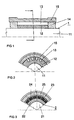
- the rotor 1 of an electrical machine consists of the shaft 11, of the rotor yoke 12 arranged above it on the shaft, which receives conductor rods 13 in longitudinal grooves, which are connected to one another on the two end faces by short-circuit rings 14, and the clamping sleeve 15.
- the rotor yoke 12 is made of a commercially available steel with a strength of 380 N / mm 2
- the adapter sleeve 15 consists of a high-strength steel with a strength of 1,300 N / mm 2 , for example the steel P900N from Krupp.
- the rotor yoke 12 with the inserted conductor bars 13 and the short-circuit rings 14 and the clamping sleeve 15 has first been expanded beyond the yield strength of the rotor yoke material, as a result of which the clamping sleeve 15 the rotor yoke 12 with the inserted conductor bars 13 and the short-circuit rings 14 with high prestress encloses. Subsequently, the active part consisting of the rotor yoke, conductor bars, short-circuit rings and clamping sleeve was applied to the shaft 11 using the technology Two-stage oil press fit "applied.
- FIG. 3 there is the one to be applied to a rotor shaft 21 Active part 2 from a rotor yoke 22, on the outer surface the permanent magnet 23 glued on the rotor yoke, from a protective sleeve 24 in the form of a copper sleeve with a Wall thickness of about 0.8 mm and from the adapter sleeve 25.
- Materials for rotor yoke 22 and adapter sleeve 25 correspond to those of the embodiment according to Figures 1 and 2. Production this active part and applying the active part the rotor shaft 21 take place in the same way as in the exemplary embodiment according to FIG. 1.
Landscapes
- Engineering & Computer Science (AREA)
- Power Engineering (AREA)
- Permanent Field Magnets Of Synchronous Machinery (AREA)
- Iron Core Of Rotating Electric Machines (AREA)
- Synchronous Machinery (AREA)
- Manufacture Of Motors, Generators (AREA)
- Insulation, Fastening Of Motor, Generator Windings (AREA)
Abstract
Description
- Figur 1 und 2
- einen Läufer mit Kurzschlußwicklung im Längsund Querschnitt und
- Figur 3
- einen Läufer mit Permanentmagneten im Querschnitt.
Claims (2)
- Rotor für eine dynamoelektrische Maschine, dessen äußerer, im Querschnitt kreisring-förmiger Bereich aus einem Läuferjoch aus einem magnetisierbaren Stahl,
aus in oder auf dem Läuferjoch angeordneten Bauteilen zur Erzeugung des Magnetfeldes
und aus einer sich über die ganze Länge des Rotors erstrekkenden, im Preßsitz aufsitzenden rohrförmigen Spannhülse aus einem hochfesten Metall besteht,
dadurch gekennzeichnet,
daß die rohrförmige Spannhülse (15) durch Aufweitung des mit den Bauteilen (13) und der Spannhülse bestückten Läuferjoches (12) über die Streckgrenze des Läuferjochmaterials hinaus radial elastisch vorgespannt ist,
wobei der magnetisierbare Stahl des Läuferjochs (12) eine Streckgrenze kleiner/gleich 400 N/mm2 aufweist und die rohrförmige Spannhülse (15) eine Wanddicke von wenigstens 3 mm aufweist und aus einem Stahl der Festigkeit größer 1000 N/mm2 besteht. - Rotor nach Anspruch 1,
dadurch gekennzeichnet,
daß die zur Erzeugung des Magnetfeldes dienenden Bauteile aus auf das Läuferjoch (22) aufgeklebten Permanentmagneten(23) bestehen und daß zwischen diesen Permanentmagneten (23) und der Spannhülse (25) eine rohrförmige mechanische Schutzschicht (24) angeordnet ist.
Applications Claiming Priority (2)
| Application Number | Priority Date | Filing Date | Title |
|---|---|---|---|
| DE19736710A DE19736710B4 (de) | 1997-08-18 | 1997-08-18 | Rotor für eine dynamoelektrische Maschine |
| DE19736710 | 1997-08-18 |
Publications (3)
| Publication Number | Publication Date |
|---|---|
| EP0977340A2 true EP0977340A2 (de) | 2000-02-02 |
| EP0977340A3 EP0977340A3 (de) | 2001-04-18 |
| EP0977340B1 EP0977340B1 (de) | 2002-10-30 |
Family
ID=7839936
Family Applications (1)
| Application Number | Title | Priority Date | Filing Date |
|---|---|---|---|
| EP98250294A Expired - Lifetime EP0977340B1 (de) | 1997-08-18 | 1998-08-18 | Rotor für eine dynamoelektrische Maschine |
Country Status (3)
| Country | Link |
|---|---|
| EP (1) | EP0977340B1 (de) |
| JP (1) | JP4057710B2 (de) |
| DE (1) | DE19736710B4 (de) |
Cited By (1)
| Publication number | Priority date | Publication date | Assignee | Title |
|---|---|---|---|---|
| US10951101B2 (en) | 2015-12-08 | 2021-03-16 | Rolls-Royce Plc | Induction motor rotor and a method of manufacturing the same |
Families Citing this family (4)
| Publication number | Priority date | Publication date | Assignee | Title |
|---|---|---|---|---|
| DE10224776A1 (de) * | 2002-06-04 | 2004-03-11 | Magnet-Motor Gesellschaft Für Magnetmotorische Technik Mbh | Elektrische Maschine |
| EP2887502B1 (de) | 2013-12-18 | 2016-10-05 | Skf Magnetic Mechatronics | Rotoranordnung mit Permanentmagneten und Verfahren zur Herstellung |
| CN111682663A (zh) * | 2020-06-11 | 2020-09-18 | 哈尔滨电气动力装备有限公司 | 异步电机实心转子结构 |
| DE102022212073A1 (de) * | 2022-11-15 | 2024-05-16 | Zf Friedrichshafen Ag | Elektrische Maschine, Fahrzeug und Kurzschlussläufer für eine elektrische Maschine |
Family Cites Families (6)
| Publication number | Priority date | Publication date | Assignee | Title |
|---|---|---|---|---|
| DE2140358A1 (de) * | 1971-08-11 | 1973-06-20 | Mo Wysschee Tekhn Utschilischt | Streckverfahren fuer bandagenringe und presseinrichtung zum durchfuehren dieses verfahrens |
| DE2530437B2 (de) * | 1975-07-08 | 1979-04-19 | Galina Alexandrovna Zagorodnaya Geb. Poluektova | Zylindermantelförmige Bandage (Läuferkappe) zur Befestigung des Wickelkopfes der Läuferwicklung einer elektrischen Maschine |
| US5563463A (en) * | 1988-06-08 | 1996-10-08 | General Electric Company | Permanent magnet rotor |
| US4918802A (en) * | 1989-02-06 | 1990-04-24 | Franklin Electric Co., Inc. | Method and apparatus for making permanent magnet rotors |
| US5486730A (en) * | 1993-03-18 | 1996-01-23 | Solar Turbines Incorporated | Rotor assembly |
| DE19532848A1 (de) * | 1995-09-06 | 1997-03-13 | Abb Patent Gmbh | Verfahren und Vorrichtung zur Montage und Demontage von Rotorkappen von Generatoren |
-
1997
- 1997-08-18 DE DE19736710A patent/DE19736710B4/de not_active Expired - Lifetime
-
1998
- 1998-08-17 JP JP23095898A patent/JP4057710B2/ja not_active Expired - Fee Related
- 1998-08-18 EP EP98250294A patent/EP0977340B1/de not_active Expired - Lifetime
Cited By (1)
| Publication number | Priority date | Publication date | Assignee | Title |
|---|---|---|---|---|
| US10951101B2 (en) | 2015-12-08 | 2021-03-16 | Rolls-Royce Plc | Induction motor rotor and a method of manufacturing the same |
Also Published As
| Publication number | Publication date |
|---|---|
| DE19736710B4 (de) | 2005-05-25 |
| EP0977340B1 (de) | 2002-10-30 |
| JP4057710B2 (ja) | 2008-03-05 |
| DE19736710A1 (de) | 1999-02-25 |
| EP0977340A3 (de) | 2001-04-18 |
| JPH11136887A (ja) | 1999-05-21 |
Similar Documents
| Publication | Publication Date | Title |
|---|---|---|
| EP2569848B1 (de) | Verfahren zur herstellung eines elektromotors | |
| EP0631364B1 (de) | Rotor und Verfahren zur Herstellung desselben | |
| DE69504318T2 (de) | Elektrische maschinen und ihre komponenten die folienwellenlager enthalten | |
| DE102014104677A1 (de) | Rotorteil zur Befestigung an der Welle eines rotierenden Elektromotors, Rotor mit Rotorteil, und Verfahren zur Herstellung eines rotierenden Elektromotors und eines Rotors | |
| DE1942855B2 (de) | Permanentmagnetlaeufer | |
| DE2737959B2 (de) | Anordnung zum Verspannen einer Luftspaltwicklung im Ständer einer elektrischen Maschine | |
| EP3676939B1 (de) | Halterung von stator im gehäuse durch federelemente | |
| DE2924863C2 (de) | Anordnung zur Befestigung einer Luftspaltwicklung | |
| DE3245699A1 (de) | Kommutator und verfahren zu seiner herstellung | |
| EP0977340B1 (de) | Rotor für eine dynamoelektrische Maschine | |
| DE102009005956A1 (de) | Magnetring | |
| EP3646439A1 (de) | Rotor für eine elektromaschine | |
| EP2896837B1 (de) | Verfahren zur Herstellung einer Rotoranordnung für eine Vakuumpumpe und Rotoranordnung für eine Vakuumpumpe | |
| DE2333621A1 (de) | Rotorwickelkopfabstuetzung fuer schnelllaufende elektrische maschinen, insbesondere turbogenerator | |
| DE4239754C2 (de) | Läufer für eine elektrische Maschine | |
| CH665063A5 (de) | Asynchronlaeufer. | |
| DE102018206138A1 (de) | Gehäuse eines Elektromotors | |
| EP3261222A2 (de) | Rotorsystem für eine elektrische maschine, elektrische maschine mit dem rotorsystem und herstellungsverfahren für das rotorsystem | |
| EP2006979B1 (de) | Verfahren zum Herstellen einer Rotorwelle elektrischer Generatoren für die Stromgewinnung in Kraftwerken | |
| DE29510521U1 (de) | Rotor für elektrische Maschinen und Geräte, insbesondere Schrittmotoren | |
| DE102016202264A1 (de) | Rotor für eine Elektromaschine, Elektromaschine sowie Verfahren zur Herstellung eines derartigen Rotors | |
| AT202638B (de) | Verfahren zur Herstellung von Statorsätzen aus zwei zylindrischen, ineinander schiebbaren Teilen aus ferromagnetischem Material | |
| DE2724009A1 (de) | Verfahren und vorrichtung zur fertigung eines staenders einer dynamoelektrischen maschine | |
| DE102018204437A1 (de) | Verfahren zur Montage eines Bauelementes auf einer Hohlwelle sowie ein auf diese Weise hergestellter Rotor für eine elektrische Maschine | |
| EP3261217B1 (de) | Rotorsystem für eine elektrische maschine, elektrische maschine mit dem rotorsystem und herstellungsverfahren für das rotorsystem |
Legal Events
| Date | Code | Title | Description |
|---|---|---|---|
| PUAI | Public reference made under article 153(3) epc to a published international application that has entered the european phase |
Free format text: ORIGINAL CODE: 0009012 |
|
| AK | Designated contracting states |
Kind code of ref document: A2 Designated state(s): CH FI FR IT LI |
|
| AX | Request for extension of the european patent |
Free format text: AL;LT;LV;MK;RO;SI |
|
| PUAL | Search report despatched |
Free format text: ORIGINAL CODE: 0009013 |
|
| AK | Designated contracting states |
Kind code of ref document: A3 Designated state(s): AT BE CH CY DE DK ES FI FR GB GR IE IT LI LU MC NL PT SE |
|
| AX | Request for extension of the european patent |
Free format text: AL;LT;LV;MK;RO;SI |
|
| 17P | Request for examination filed |
Effective date: 20010806 |
|
| AKX | Designation fees paid |
Free format text: CH FI FR IT LI |
|
| REG | Reference to a national code |
Ref country code: DE Ref legal event code: 8566 |
|
| GRAG | Despatch of communication of intention to grant |
Free format text: ORIGINAL CODE: EPIDOS AGRA |
|
| GRAG | Despatch of communication of intention to grant |
Free format text: ORIGINAL CODE: EPIDOS AGRA |
|
| GRAH | Despatch of communication of intention to grant a patent |
Free format text: ORIGINAL CODE: EPIDOS IGRA |
|
| 17Q | First examination report despatched |
Effective date: 20020314 |
|
| GRAH | Despatch of communication of intention to grant a patent |
Free format text: ORIGINAL CODE: EPIDOS IGRA |
|
| GRAA | (expected) grant |
Free format text: ORIGINAL CODE: 0009210 |
|
| AK | Designated contracting states |
Kind code of ref document: B1 Designated state(s): CH FI FR IT LI |
|
| REG | Reference to a national code |
Ref country code: CH Ref legal event code: NV Representative=s name: SIEMENS SCHWEIZ AG Ref country code: CH Ref legal event code: EP |
|
| ET | Fr: translation filed | ||
| PLBE | No opposition filed within time limit |
Free format text: ORIGINAL CODE: 0009261 |
|
| STAA | Information on the status of an ep patent application or granted ep patent |
Free format text: STATUS: NO OPPOSITION FILED WITHIN TIME LIMIT |
|
| 26N | No opposition filed |
Effective date: 20030731 |
|
| PG25 | Lapsed in a contracting state [announced via postgrant information from national office to epo] |
Ref country code: IT Free format text: LAPSE BECAUSE OF NON-PAYMENT OF DUE FEES Effective date: 20050818 |
|
| REG | Reference to a national code |
Ref country code: CH Ref legal event code: PCAR Free format text: SIEMENS SCHWEIZ AG;INTELLECTUAL PROPERTY FREILAGERSTRASSE 40;8047 ZUERICH (CH) |
|
| PGFP | Annual fee paid to national office [announced via postgrant information from national office to epo] |
Ref country code: CH Payment date: 20121113 Year of fee payment: 15 |
|
| PGFP | Annual fee paid to national office [announced via postgrant information from national office to epo] |
Ref country code: FI Payment date: 20130813 Year of fee payment: 16 |
|
| PGFP | Annual fee paid to national office [announced via postgrant information from national office to epo] |
Ref country code: FR Payment date: 20130814 Year of fee payment: 16 |
|
| REG | Reference to a national code |
Ref country code: CH Ref legal event code: PL |
|
| PG25 | Lapsed in a contracting state [announced via postgrant information from national office to epo] |
Ref country code: LI Free format text: LAPSE BECAUSE OF NON-PAYMENT OF DUE FEES Effective date: 20130831 Ref country code: CH Free format text: LAPSE BECAUSE OF NON-PAYMENT OF DUE FEES Effective date: 20130831 |
|
| PG25 | Lapsed in a contracting state [announced via postgrant information from national office to epo] |
Ref country code: FI Free format text: LAPSE BECAUSE OF NON-PAYMENT OF DUE FEES Effective date: 20140818 |
|
| REG | Reference to a national code |
Ref country code: FR Ref legal event code: ST Effective date: 20150430 |
|
| PG25 | Lapsed in a contracting state [announced via postgrant information from national office to epo] |
Ref country code: FR Free format text: LAPSE BECAUSE OF NON-PAYMENT OF DUE FEES Effective date: 20140901 |