EP0977341A2 - Ensemble moteur électrique et module d'électronique de puissance - Google Patents
Ensemble moteur électrique et module d'électronique de puissance Download PDFInfo
- Publication number
- EP0977341A2 EP0977341A2 EP99113273A EP99113273A EP0977341A2 EP 0977341 A2 EP0977341 A2 EP 0977341A2 EP 99113273 A EP99113273 A EP 99113273A EP 99113273 A EP99113273 A EP 99113273A EP 0977341 A2 EP0977341 A2 EP 0977341A2
- Authority
- EP
- European Patent Office
- Prior art keywords
- power electronics
- electrical
- electronics unit
- electrical machine
- parting line
- Prior art date
- Legal status (The legal status is an assumption and is not a legal conclusion. Google has not performed a legal analysis and makes no representation as to the accuracy of the status listed.)
- Ceased
Links
- 230000006835 compression Effects 0.000 description 2
- 238000007906 compression Methods 0.000 description 2
- 238000004519 manufacturing process Methods 0.000 description 2
- 229910052751 metal Inorganic materials 0.000 description 2
- 239000002184 metal Substances 0.000 description 2
- 241001295925 Gegenes Species 0.000 description 1
- 229910052782 aluminium Inorganic materials 0.000 description 1
- XAGFODPZIPBFFR-UHFFFAOYSA-N aluminium Chemical compound [Al] XAGFODPZIPBFFR-UHFFFAOYSA-N 0.000 description 1
- 239000000428 dust Substances 0.000 description 1
- 238000012423 maintenance Methods 0.000 description 1
- 239000000463 material Substances 0.000 description 1
- 238000007789 sealing Methods 0.000 description 1
- 238000004804 winding Methods 0.000 description 1
Images

Classifications
-
- H—ELECTRICITY
- H02—GENERATION; CONVERSION OR DISTRIBUTION OF ELECTRIC POWER
- H02K—DYNAMO-ELECTRIC MACHINES
- H02K5/00—Casings; Enclosures; Supports
- H02K5/04—Casings or enclosures characterised by the shape, form or construction thereof
- H02K5/22—Auxiliary parts of casings not covered by groups H02K5/06-H02K5/20, e.g. shaped to form connection boxes or terminal boxes
- H02K5/225—Terminal boxes or connection arrangements
-
- H—ELECTRICITY
- H02—GENERATION; CONVERSION OR DISTRIBUTION OF ELECTRIC POWER
- H02K—DYNAMO-ELECTRIC MACHINES
- H02K11/00—Structural association of dynamo-electric machines with electric components or with devices for shielding, monitoring or protection
- H02K11/30—Structural association with control circuits or drive circuits
- H02K11/33—Drive circuits, e.g. power electronics
-
- H—ELECTRICITY
- H02—GENERATION; CONVERSION OR DISTRIBUTION OF ELECTRIC POWER
- H02K—DYNAMO-ELECTRIC MACHINES
- H02K11/00—Structural association of dynamo-electric machines with electric components or with devices for shielding, monitoring or protection
- H02K11/0094—Structural association with other electrical or electronic devices
-
- H—ELECTRICITY
- H02—GENERATION; CONVERSION OR DISTRIBUTION OF ELECTRIC POWER
- H02K—DYNAMO-ELECTRIC MACHINES
- H02K11/00—Structural association of dynamo-electric machines with electric components or with devices for shielding, monitoring or protection
- H02K11/04—Structural association of dynamo-electric machines with electric components or with devices for shielding, monitoring or protection for rectification
- H02K11/049—Rectifiers associated with stationary parts, e.g. stator cores
- H02K11/05—Rectifiers associated with casings, enclosures or brackets
-
- H—ELECTRICITY
- H02—GENERATION; CONVERSION OR DISTRIBUTION OF ELECTRIC POWER
- H02K—DYNAMO-ELECTRIC MACHINES
- H02K7/00—Arrangements for handling mechanical energy structurally associated with dynamo-electric machines, e.g. structural association with mechanical driving motors or auxiliary dynamo-electric machines
- H02K7/10—Structural association with clutches, brakes, gears, pulleys or mechanical starters
- H02K7/106—Structural association with clutches, brakes, gears, pulleys or mechanical starters with dynamo-electric brakes
Definitions
- the invention relates to a structural unit consisting of an electrical machine and a Power electronics unit for use in a vehicle.
- Units of this type are used in electrically powered vehicles, used for example in industrial trucks. With the power electronics unit it is often an inverter.
- the electrical machine can for example as a drive motor of the vehicle. Here the Drive motor supplied with electrical energy via the power electronics unit.
- the electrical machine can be designed as a generator be, the electrical energy generated by the generator Power electronics unit is supplied.
- the electrical machine and the Power electronics unit arranged separately. Often are a housing of the electrical machine and a housing of the power electronics unit separately attached to each other on a frame of the vehicle.
- An electrical connection the electrical machine with the power electronics unit is usually used Cables and electrical screw connections made. The execution and the The type of cable and screw connections used depend on the sizes of the current to be transmitted and the voltages that occur. Since the electrical screw connections against external influences such as dirt or Moisture must be protected are known generic Units provide the screw connections with an additional cover.
- the manufacture and maintenance of well-known building units turns out time consuming and material intensive.
- the present invention is therefore the The task is based on a simple to produce unit from an electrical Machine and a power electronics unit for use in a vehicle to provide.
- a housing part electrical machine with a housing part of the power electronics unit on a Parting line is connected and in the area of the parting line electrical pressure contacts are arranged.
- the parting line is preferably flat.
- the Power electronics unit is directly on the electrical machine, for example attached by screwing, creating the flat parting line.
- each pressure contact has one on the power electronics unit arranged and arranged on the electrical machine contact point.
- At least one seal is expedient in the area of the parting line arranged.
- the seal is between the housing parts of the Power electronics unit and the electrical machine arranged and protects the Pressure contacts against external influences such as dust and moisture.
- the electrical pressure contacts are at least partially for electrical connection the power electronics unit provided with the electrical machine. Between the electrical machine and the power electronics unit are therefore none Cable connections outside the housing required.
- the electrical Pressure contacts at least partially for the electrical connection of the Power electronics unit with other electrical components of the vehicle provided, with lines to these components through the housing part of the electrical machine are guided.
- other electrical components for example, a braking resistor or a power supply unit.
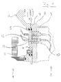
- Figure 1 shows a section of an electrical machine 1 and a section a power electronics unit 2.
- a metal housing 3 of the electrical machine is used as a housing part 4 a plastic connecting plate and sealed against the metal housing 3 by means of a seal 5.
- a stator winding 6 of the electrical machine 1 is also part of a stator winding 6 of the electrical machine 1.
- the electrical machine 1 is the electrical machine 1 as a motor, preferably as AC motor executed.
- a planar parting line 7 separates the housing 3, 4 of the electrical machine 1 from a housing 8, 9 of the power electronics unit 2, which in the present Embodiment is designed as a converter.
- the housing part 8 is the Power electronics unit from an aluminum plate and the housing part 9 from one insulating connection plate formed.
- a circumferential seal 13 protects the Area of the parting line 7 arranged electrical elements in front of outer Influences.
- the housing parts 4 and 9 have in the region of the parting line 7 electrical pressure contacts 10.
- the pressure contacts are at one Assembling the housing parts 4 and 9 automatically closed, two Contact surfaces 11, 12 are pressed together.
- FIG. 2 shows the housing part 4 of the electrical machine and FIG. 3 the housing parts 8, 9 shows the power electronics unit.
- the contact surfaces 11 on the electrical Machine are rigidly attached to the housing part 4 and are connected to the cable 14 corresponding connections of the electrical machine 1 or with others, units arranged outside the electrical machine 1 are connected.
- the contact points are located in the housing part 9 of the power electronics unit 12, which is biased towards the contact points 11 by means of compression springs 15 are.
- the compression springs ensure that there is always sufficient pressure between the Contact points 11 and 12.
- Electrical cables 16 connect the contact points 12 to the corresponding connections of the power electronics unit 2.
- the housing part 4 of the electrical machine has a circumferential recess 17 with a circumferential increase 18 of the housing part 8 of the Power electronics unit 2 corresponds.
Landscapes
- Engineering & Computer Science (AREA)
- Power Engineering (AREA)
- Microelectronics & Electronic Packaging (AREA)
- Motor Or Generator Frames (AREA)
- Casings For Electric Apparatus (AREA)
Applications Claiming Priority (2)
| Application Number | Priority Date | Filing Date | Title |
|---|---|---|---|
| DE19831829A DE19831829A1 (de) | 1998-07-15 | 1998-07-15 | Baueinheit aus einer elektrischen Maschine und einer Leistungselektronikeinheit |
| DE19831829 | 1998-07-15 |
Publications (2)
| Publication Number | Publication Date |
|---|---|
| EP0977341A2 true EP0977341A2 (fr) | 2000-02-02 |
| EP0977341A3 EP0977341A3 (fr) | 2001-02-14 |
Family
ID=7874169
Family Applications (1)
| Application Number | Title | Priority Date | Filing Date |
|---|---|---|---|
| EP99113273A Ceased EP0977341A3 (fr) | 1998-07-15 | 1999-07-08 | Ensemble moteur électrique et module d'électronique de puissance |
Country Status (3)
| Country | Link |
|---|---|
| US (1) | US6334796B1 (fr) |
| EP (1) | EP0977341A3 (fr) |
| DE (1) | DE19831829A1 (fr) |
Cited By (2)
| Publication number | Priority date | Publication date | Assignee | Title |
|---|---|---|---|---|
| WO2015078459A3 (fr) * | 2013-11-26 | 2015-12-30 | Schaeffler Technologies AG & Co. KG | Module électronique de puissance et module hybride comportant un dispositif de connexion électrique de moteur électrique |
| EP3182448A1 (fr) | 2015-12-18 | 2017-06-21 | Karlsruher Institut für Technologie | Structure de liaison modulaire multifonctionnelle |
Families Citing this family (10)
| Publication number | Priority date | Publication date | Assignee | Title |
|---|---|---|---|---|
| DE10018986A1 (de) * | 2000-04-17 | 2001-10-18 | Still Gmbh | Baueinheit aus einem Verbrennungsmotor, einer elektrischen Maschine und einer Pumpe |
| TW549662U (en) * | 2001-06-08 | 2003-08-21 | Hon Hai Prec Ind Co Ltd | Electrical connector |
| US7322861B2 (en) * | 2005-11-23 | 2008-01-29 | Lear Corporation | Power supply circuit for removable automotive interior systems with integrated switching function |
| DE102008004830A1 (de) * | 2008-01-17 | 2009-07-30 | Continental Automotive Gmbh | Elektronikmodul, elektrische Vorrichtung mit dem Elektronikmodul, Kraftfahrzeug und Verfahren zum Montieren einer elektrischen Vorrichtung mit dem Elektronikmodul |
| DE102014003203A1 (de) * | 2014-03-06 | 2015-09-10 | Liebherr-Mining Equipment Colmar Sas | Arbeitsmaschine, insbesondere Muldenkipper oder Truck |
| DE102014003375A1 (de) * | 2014-03-06 | 2015-09-10 | Liebherr-Mining Equipment Colmar Sas | Arbeitsmaschine, insbesondere Muldenkipper oder Truck |
| TWM482874U (zh) * | 2014-04-01 | 2014-07-21 | Insert Entpr Co Ltd | Rf射頻連接器 |
| DE102016106104A1 (de) | 2016-04-04 | 2017-10-05 | Linde Material Handling Gmbh | Elektrische Motoreinheit für mobile Arbeitsmaschine |
| DE102016107083B4 (de) | 2016-04-18 | 2019-05-23 | Semikron Elektronik Gmbh & Co. Kg | Leistungselektronische Anordnung und Fahrzeug hiermit |
| DE102022125494A1 (de) | 2022-10-04 | 2024-04-04 | Liebherr-Werk Nenzing Gmbh | Schutzvorrichtung und Arbeitsmaschine |
Citations (2)
| Publication number | Priority date | Publication date | Assignee | Title |
|---|---|---|---|---|
| FR2326070A1 (fr) * | 1975-09-27 | 1977-04-22 | Bosch Gmbh Robert | Machine electrique sans bagues collectrices |
| GB2317210A (en) * | 1996-09-13 | 1998-03-18 | Bosch Gmbh Robert | Electrohydraulic unit for pressure control in slip-regulated brake systems of motor vehicles |
Family Cites Families (13)
| Publication number | Priority date | Publication date | Assignee | Title |
|---|---|---|---|---|
| DE1220042B (de) * | 1962-07-25 | 1966-06-30 | Heinz Schaeffersmann | Aus mehreren Ventilen bestehendes Gleichrichteraggregat fuer einen Elektromotor |
| DE1963497A1 (de) | 1969-08-25 | 1971-03-04 | Schwermaschb Kom Ernst Thaelma | Verfahren zum Walzen von zweiseitig symmetrischen Vollprofilen |
| DE2913937C2 (de) * | 1979-04-06 | 1986-08-21 | Frankl & Kirchner GmbH & Co KG Fabrik für Elektromotoren u. elektrische Apparate, 6830 Schwetzingen | Leiterplatte mit Steckverbinder |
| IT1141680B (it) * | 1980-11-03 | 1986-10-08 | Necchi Spa | Morsettiera e scatola rele' in motocompressori per apparati frigoriferi |
| US4582374A (en) * | 1981-10-26 | 1986-04-15 | Amp Incorporated | High density interconnect system |
| US5290121A (en) * | 1992-05-28 | 1994-03-01 | The United States Of America As Represented By The Administrator Of The National Aeronautics And Space Administration | System for the installation and replacement of components in hostile environments |
| IT1255190B (it) * | 1992-06-30 | 1995-10-20 | Giuseppe Marchisi | Dispositivo di interfaccia di comando per un motore elettrico |
| DE9402335U1 (de) * | 1994-02-12 | 1994-04-07 | Moser Elektrogeräte GmbH, 78089 Unterkirnach | Akkubetriebenes Elektrogerät |
| DE4411784C2 (de) * | 1994-04-06 | 1998-06-18 | Pfisterer Elektrotech Karl | Verbindungssystem zum Anschließen von isolierten Kabeln an elektrische Geräte |
| DE4423403A1 (de) * | 1994-07-04 | 1996-01-11 | Stierlen Maquet Ag | Verbindungsmodul |
| DE4446243C1 (de) * | 1994-12-23 | 1996-03-07 | Stegmann Max Antriebstech | Drehwinkel-Meßvorrichtung |
| DE29521213U1 (de) * | 1995-04-21 | 1997-01-09 | Contact GmbH Elektrische Bauelemente, 70565 Stuttgart | Steckverbindersystem |
| DE19634097C2 (de) * | 1996-08-23 | 1998-07-09 | Kostal Leopold Gmbh & Co Kg | Elektromotor |
-
1998
- 1998-07-15 DE DE19831829A patent/DE19831829A1/de not_active Withdrawn
-
1999
- 1999-07-08 EP EP99113273A patent/EP0977341A3/fr not_active Ceased
- 1999-07-12 US US09/351,960 patent/US6334796B1/en not_active Expired - Fee Related
Patent Citations (2)
| Publication number | Priority date | Publication date | Assignee | Title |
|---|---|---|---|---|
| FR2326070A1 (fr) * | 1975-09-27 | 1977-04-22 | Bosch Gmbh Robert | Machine electrique sans bagues collectrices |
| GB2317210A (en) * | 1996-09-13 | 1998-03-18 | Bosch Gmbh Robert | Electrohydraulic unit for pressure control in slip-regulated brake systems of motor vehicles |
Cited By (6)
| Publication number | Priority date | Publication date | Assignee | Title |
|---|---|---|---|---|
| WO2015078459A3 (fr) * | 2013-11-26 | 2015-12-30 | Schaeffler Technologies AG & Co. KG | Module électronique de puissance et module hybride comportant un dispositif de connexion électrique de moteur électrique |
| CN105765791A (zh) * | 2013-11-26 | 2016-07-13 | 舍弗勒技术股份两合公司 | 具有电动机电流接头的功率电子器件模块以及混合动力模块 |
| CN105765791B (zh) * | 2013-11-26 | 2018-11-06 | 舍弗勒技术股份两合公司 | 具有电动机电流接头的功率电子器件模块以及混合动力模块 |
| US10658900B2 (en) | 2013-11-26 | 2020-05-19 | Schaeffler Technologies AG & Co. KG | Power electronics module and hybrid module with an E-motor power connection |
| EP3182448A1 (fr) | 2015-12-18 | 2017-06-21 | Karlsruher Institut für Technologie | Structure de liaison modulaire multifonctionnelle |
| DE102015122250A1 (de) | 2015-12-18 | 2017-06-22 | Karlsruher Institut für Technologie | Multifunktionale Modulverbindungsstruktur |
Also Published As
| Publication number | Publication date |
|---|---|
| US6334796B1 (en) | 2002-01-01 |
| DE19831829A1 (de) | 2000-01-20 |
| EP0977341A3 (fr) | 2001-02-14 |
Similar Documents
| Publication | Publication Date | Title |
|---|---|---|
| DE4337390C2 (de) | Antriebseinheit für Verstellsysteme in Kraftfahrzeugen | |
| EP1703620B1 (fr) | Entraînement électrique | |
| EP0977341A2 (fr) | Ensemble moteur électrique et module d'électronique de puissance | |
| EP3358921B1 (fr) | Dispositif électronique de puissance et véhicule correspondant | |
| EP2076413A1 (fr) | Systeme de raccordement comprenant un cablage externe sur des logements de moteurs d'essuie-glaces | |
| DE112013000628T5 (de) | Elektrischer Kompressor | |
| DE102009016756A1 (de) | Abschirmverbinderstruktur | |
| DE112014004297T5 (de) | Leiter-Rahmen, Elektronik-Steuervorrichtung die einen Leiter-Rahmen verwendet und Leiter-Rahmen-Montageverfahren | |
| DE112020003914T5 (de) | Elektrisch angetriebene Antriebsvorrichtung und Verfahren zum Montieren einer elektrisch angetriebenen Antriebsvorrichtung | |
| DE102020214312A1 (de) | Elektronikkomponenten-Befestigungsstruktur und Stromdetektionsvorrichtung | |
| EP3657566B1 (fr) | Connecteur pour batterie, batterie et véhicule automobile | |
| DE112020002687T5 (de) | Leistungsumsetzungsvorrichtung | |
| DE10351677A1 (de) | Mehrfachscheibe mit einer Leitungsdurchführung | |
| DE102008023108A1 (de) | Kantenverbinder für ein Solarmodul, Steckverbinder zur Verbindung mit dem Kantenverbinder sowie Solarmodul mit einem derartigen Kantenverbinder | |
| EP1703617B1 (fr) | Entraînement électrique | |
| EP4002968B1 (fr) | Onduleur et son procédé de fabrication | |
| DE102008001378A1 (de) | Sicherung | |
| DE102010053135A1 (de) | Montageeinheit für ein elektrisches Leistungsteil in einem Flurförderzeug | |
| DE202023101719U1 (de) | E-Maschinenanordnung und Antriebsanordnung mit der E-Maschinenanordnung und Inverteranordnung | |
| DE102019205781A1 (de) | Antriebsvorrichtung umfassend einen Elektromotor und einen Wechselrichter und Kraftfahrzeug | |
| DE102019102713A1 (de) | Antriebseinheit | |
| DE102012112336A1 (de) | Anschlussblock, Halbleitervorrichtung und fahrzeug-gestützte drehende elektrische Maschine | |
| EP0834966A2 (fr) | Connecteur enfichable pour plaquette à circuits située au-dessous d'un couvercle | |
| DE102008058926B4 (de) | Elektromotorische Antriebseinheit für Stellantriebe in Kraftfahrzeug | |
| DE102020214220A1 (de) | Gehäuseanordnung, Stromrichter, Kraftfahrzeug sowie Verfahren zur Herstellung einer Gehäuseanordnung |
Legal Events
| Date | Code | Title | Description |
|---|---|---|---|
| PUAI | Public reference made under article 153(3) epc to a published international application that has entered the european phase |
Free format text: ORIGINAL CODE: 0009012 |
|
| AK | Designated contracting states |
Kind code of ref document: A2 Designated state(s): DE FR GB IT |
|
| AX | Request for extension of the european patent |
Free format text: AL;LT;LV;MK;RO;SI |
|
| PUAL | Search report despatched |
Free format text: ORIGINAL CODE: 0009013 |
|
| AK | Designated contracting states |
Kind code of ref document: A3 Designated state(s): AT BE CH CY DE DK ES FI FR GB GR IE IT LI LU MC NL PT SE |
|
| AX | Request for extension of the european patent |
Free format text: AL;LT;LV;MK;RO;SI |
|
| RIC1 | Information provided on ipc code assigned before grant |
Free format text: 7H 02K 5/22 A, 7H 02K 11/04 B |
|
| 17P | Request for examination filed |
Effective date: 20010718 |
|
| AKX | Designation fees paid |
Free format text: DE FR GB IT |
|
| STAA | Information on the status of an ep patent application or granted ep patent |
Free format text: STATUS: THE APPLICATION HAS BEEN REFUSED |
|
| 18R | Application refused |
Effective date: 20081212 |