EP0977424A2 - Drucken gerasterter Halbtöne unter Verwendung von torischen Filtern - Google Patents
Drucken gerasterter Halbtöne unter Verwendung von torischen Filtern Download PDFInfo
- Publication number
- EP0977424A2 EP0977424A2 EP99111332A EP99111332A EP0977424A2 EP 0977424 A2 EP0977424 A2 EP 0977424A2 EP 99111332 A EP99111332 A EP 99111332A EP 99111332 A EP99111332 A EP 99111332A EP 0977424 A2 EP0977424 A2 EP 0977424A2
- Authority
- EP
- European Patent Office
- Prior art keywords
- filter
- pattern
- dither matrix
- support
- region
- Prior art date
- Legal status (The legal status is an assumption and is not a legal conclusion. Google has not performed a legal analysis and makes no representation as to the accuracy of the status listed.)
- Granted
Links
Images


Classifications
-
- H—ELECTRICITY
- H04—ELECTRIC COMMUNICATION TECHNIQUE
- H04N—PICTORIAL COMMUNICATION, e.g. TELEVISION
- H04N1/00—Scanning, transmission or reproduction of documents or the like, e.g. facsimile transmission; Details thereof
- H04N1/40—Picture signal circuits
- H04N1/405—Halftoning, i.e. converting the picture signal of a continuous-tone original into a corresponding signal showing only two levels
- H04N1/4051—Halftoning, i.e. converting the picture signal of a continuous-tone original into a corresponding signal showing only two levels producing a dispersed dots halftone pattern, the dots having substantially the same size
Definitions
- the present invention relates generally to halftone images, and more particularly to methods of generating screens for printing halftone images on printing engines.
- a printer can be designed to print a picture as a halftone or gray scale image.
- a halftone image each pixel of the image either has a dot printed or not printed.
- a gray scale image each dot on a pixel is refined to have one of many gray levels.
- Halftoning creates the illusion of continuous tone images by judicious arrangement of binary picture elements, simulating the continuous tone image.
- a halftone image is usually easier and cheaper to generate than a gray scale image.
- Many relatively low cost printers are specifically designed to print halftone images.
- the image must first be transformed to a halftone image using a screen or set of screens.
- One objective of the printing industry is to develop appropriate transformation techniques so that the halftone image becomes virtually indistinguishable from the gray scale image.
- One prior art method transforms a gray scale image to a halftone image by means of a dither matrix.
- the gray scale image has many gray levels and many pixels. Each pixel has a value.
- the dither matrix occupies a physical space and has numerous elements, each with a value.
- the dither matrix is mapped over the halftone image to generate the halftone image. For a gray scale image that is larger than the dither matrix, the dither matrix is replicated or tiled to cover the entire image.
- Each pixel in the grayscale image is compared to an element in the dither matrix. If the gray scale image pixel has a larger value, no dot is printed in the corresponding halftone image position.
- the halftone image created has the same number of gray level patterns as the number of gray levels in the gray scale image. A darker area in the gray scale image is represented in the halftone image by a gray patterns with more dots.
- the dither matrix In order to generate a halftone image using the above method, the dither matrix must be carefully designed. The elements in the matrix should not be generated by a random number generator, as a fully random pattern would create a halftone image that is noisy, corrupting the content of the image.
- void-and-cluster method One prior art method of designing a dither matrix is known as the void-and-cluster method. A general discussion of this method can be found in "The Void and Cluster Method for Dither Array Generation” by Robert Ulichney, published in IS&T/SPIE Symposium on Electronic Imaging: Science and Technology , San Jose, California, 1993.
- Another prior art uses an error diffusion method to generate the halftone image. This method analyzes every pixel of the gray scale image on at a time to decide if a dot is to be printed in its halftone image. Errors from each pixel are "diffused" to subsequent neighboring pixels. Such pixel-to-pixel calculation requires intensive computation, taking much more time to generate the halftone image than a method applying dither matrices. Additionally, the error diffusion method is not suitable for vector graphics, because the values of pixels on a halftone image may not be calculated sequentially. A discussion of the error diffusion method can be found in "An Adaptive Algorithm for Spatial Grayscale" by Floyd and Steinberg, Proceeding of the Society for Information Display, Vol. 17, pp. 75-77, 1976.
- the present invention provides a method of generating a halftone image from a gray scale image using a dither matrix.
- the value of every pixel in the halftone image is determined by a direct comparison of the value in a pixel in the gray scale image to the value in an element of the matrix.
- the method is suitable for both raster and vector graphics, and is also suitable for printing engines having dot-to-dot interactions.
- each of the halftone image, the gray scale image, and the dither matrix occupy physical two-dimensional areas.
- the three areas are substantially equal to each other.
- Both the halftone image and the grayscale image have many pixels, and each pixel has a value.
- the dither matrix has many elements, each with a value.
- the method of the present invention compares the value of each pixel of the gray scale image with the value of an element in the dither matrix. The result of the comparison determines the value of the corresponding halftone image pixel.
- the dither matrix is generated by many patterns, each pattern corresponding to one gray level pattern of the halftone image. Each pattern has many elements, each with a value. The value of each element in a given pattern is determined by a special filter.
- a donut filter is used.
- Donut filters have the characteristic of peaks occurring away from the current pixel, where the filters of the prior art centered the peak on the current pixel. These prior art filters have the effect of expelling dots, producing a dispersed pattern.
- the donut filters of the present invention, with peaks away from the current pixel cause a clustering of dots.
- Stochastic clustered dot screens are generated by first selecting a transition level within the grayscale range of the image. For the lightest gray levels, lighter than the transition level, a first filter is used to design the halftone pattern. The width of the first filter depends on the gray level. Once the transition level has been reached, a donut filter is used to design the halftone pattern. Dots in the halftone pattern at the transition level serve as seeds where clustered dots are grown. By selecting the transition level at the lightest gray level, the donut filter is used for all gray levels. Clustered halftone dot patterns produced by the donut filter are moiré free, and have a halftone noise very similar to the grain noise in photographs, this producing a printed image better resembling a real photograph.
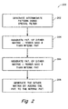
- Fig. 1 shows a computer system 100 incorporating the present invention to convert a gray scale image 102 to a halftone image 104 .
- this process includes the steps of comparing the value of each pixel of gray scale image 102 with the value of an element of a dither matrix. The result of this comparison determines the value of the corresponding pixel in halftone image 104 .
- the dither matrix is generated by first producing an intermediate pattern based on a special filter.
- the dither matrix elements with values equal to one and zero are substantially uniformly distributed within the pattern.
- a pattern is generated for an intermediate gray level, and then dots are subtracted to form patterns at lighter gray levels, and dots are added to form patterns at darker gray levels.
- an intermediate pattern is generated using the chosen filter, described below.
- patterns of the dither matrix with fewer elements having values equal to one than the intermediate pattern are generated. This is done by replacing a plurality of ones with zeroes from the intermediate pattern. The ones to be replaced are in regions where ones are clustered together, as identified by the chosen filter. The difference in the number of elements having values equal to one, from one pattern to the next pattern, is dependant on a quantization number.
- patterns of the dither matrix with fewer zeroes than the intermediate pattern are generated, This is done by replacing a plurality of zeroes with ones in the intermediate pattern.
- the zeroes to be replaced are in the regions with zeroes clustered together, as identified by the chosen filter.
- the difference in the number of elements having values equal to zero, from one pattern to the next, is dependant on the quantization number.
- step 208 the dither matrix is formed by adding all the generated patterns together.
- a second approach to generating the dither matrix begins with an intermediate pattern generated for the lightest gray level, and only adds dots for subsequent gray levels. This approach uses steps 202 , 206 , and 208 of Fig. 2 .
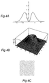
- Filters used in the prior art have their maximal value centered on the current pixel, such as Gaussian, triangular, and rectangular filters. Note that since these filters are commonly used to cover an area around a central pixel, the two dimensional representations shown in the figures are rotated about their centers to form a surface of revolution. As shown in Fig. 3A , these filters all have maxima around the current pixel. The surface of revolution of this filter is shown in Fig. 3B . This results in dot dispersion in the resulting dither matrix, as shown in Fig. 3C .
- the current invention produces clustered dots through the use of a donut filter as shown in Fig. 4A .
- the donut filter features local maxima away from the current pixel, and optionally local minima at the local pixel.
- the surface of revolution for the donut filter is shown in Fig. 4B .
- the inward inflection around the current pixel provides an energy trap that encourages dots to cluster around the current pixel.
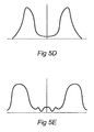
- Figs. 5A-E show a few preferred embodiments of the donut filter; again these are two dimensional representations.
- Figs 5A and 5B show rectangular donut filters with zero and nonzero values at the current pixel respectively.
- Fig. 5C shows a triangular donut filter.
- Fig. 5D shows a smoothed donut filter, with Fig. 5E showing a similar donut filter having ripple away from the maxima.
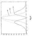
- Another preferred embodiment of the donut filter is shown in Fig. 6 .
- Donut filter 610 is the difference of lowpass Gaussian filter 620 and lowpass Gaussian filter 630 . Donut filter 610 is selected to better illustrate the present invention.
- a single type of filter e.g. Gaussian
- the present invention uses a selectable transition level within the grayscale range to switch between a first filter, for example a lowpass Gaussian filter, and a donut filter.
- a sample Gaussian lowpass filter is shown in Fig. 3 .
- Example donut filters are shown in Figs 4 through 6 .
- the process of producing the stochastic screen is improved by first selecting a transition level within the grayscale range. Next, starting at the lightest gray level, use lowpass Gaussian filter 620 to design the halftone pattern at this level using the procedure shown in Fig. 2 and described earlier. Note that the width of the Gaussian filter depends on the gray level. Once the transition level is reached, donut filter 610 is used to design the halftone patterns at all subsequent levels by the same process. Different settings of the transition level result in the donut filter being used for none, some, or all of the gray levels. For example if the transition level is set to the lightest gray level, the donut filter will be used for all gray levels.
- the particular selection of the transition level is dependant on the printing process.
- the donut filter may be used for all gray levels, or the transition level may be set by using the lowpass filter until the pattern becomes dense enough that the dots begin to touch, at which point the donut filter should be used, as it produces more stable clusters of dots.
- Fig. 9 describes step 202 of generating the intermediate pattern in more detail. Once the intermediate pattern is generated in step 350 , a region of support is selected in step 352 .
- Fig. 10 shows the steps to select a region of support.
- the first step 400 is finding the minority value in the pattern, identifying whether there are fewer ones or zeroes.
- the avenge separation D among the elements with the minority value in the pattern is calculated 402 . In one preferred embodiment, this is done by dividing the total number of elements in the pattern by the number of elements with the minority value and taking the square root.
- the diameter of the region of support is related to the sigma s. In the present example, the diameter is equal to about 3.7 * s. From its diameter, the region of support of the gaussian curve is found, 404 .
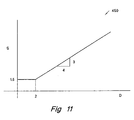
- the region of support graph 450 is generated by trial and error, through human visual response. The graph is a substantially nondecreasing-function. This is because as the average separation D of the minority value elements increases, the filter has to cover a larger area to perform meaningful filtering. If the filter does not cover a large enough area, the filtered output would be the same as the input. For the filter to cover a larger area, the sigma must increase. Based on this idea, different region of support graphs were applied to the present invention. By trial and error the region of support graph shown in Fig. 11 was found to provide acceptable patterns for the dither matrix.
- the sigma s when D is less than 2, the sigma s is constant and equal to 1.5. When D is greater than 2, sigma s is related to D by a straight line with a slope of 0.7. It should be obvious to one skilled in the art that constant values different from 1.5 (such as values ranging from 1 to 2) and slopes different from 0.0 (such as values ranging from 0.5 to 1) can be used in the present invention.
- the next step is to copy, 353 , the intermediate pattern to a dummy pattern.
- the dummy pattern is then filtered, 354 .
- Minimum and maximum positions in the dummy pattern are identified, 356 . After the maximum and minimum position are identified, the elements in the intermediate pattern are exchanged.
- Steps 204 and 206 of Fig. 2 generate patterns for the different gray levels of the dither matrix from the intermediate pattern.
- step 204 patterns of the dither matrix with fewer elements having values equal to one than the intermediate pattern are generated. This is done by replacing a plurality of ones with zeroes from the intermediate pattern. The ones to be replaced are in regions where the ones are clustered together as identified by the filter selected by the transition level.
- the region of support is calculated as described in the '418 patent or in the experimental procedure described above.
- the donut filter the same calculations are made, producing first Gaussian filter 620 .
- a second lowpass Gaussian filter 630 is generated using half the width of the first Gaussian filter 620 .
- Donut filter 610 is the difference between first Gaussian lowpass filter 620 and second lowpass Gaussian filter 630 .
- step 206 patterns of the dither matrix with more elements having values equal to one than the intermediate pattern are generated. This is done by replacing a plurality of zeroes with ones from the intermediate pattern.
- the zeroes to be replaced are in regions where the zeroes are clustered together as identified by the filter selected by the transition level.
- the region of support is calculated as described in the '418 patent.
- the donut filter the same calculations are made, producing first Gaussian filter 620 .
- a second lowpass Gaussian filter 630 is generated using a width less than that of the first Gaussian filter 620 . While a value of half the width of first Gaussian filter 620 is used in the preferred embodiment, other values may be used. Donut filter 610 is the difference between first Gaussian lowpass filter 620 and second lowpass Gaussian filter 630 .
- Fig. 7 shows gray patches rendered by stochastic screens using Gaussian filter 630 for all gray levels on the top, and on the bottom patches rendered using Gaussian filter 630 until transition gray level of 48 is reached, at which time donut filter 610 is used for the remaining gray levels.
- the left column is at gray level 66, the middle column gray level 96, and the right column gray level 126.
- the halftone patterns are printed at 75 dots per inch to allow a clear view of the dot arrangement, showing the clustering of dots in the bottom images.
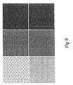
- Fig. 8 shows the effect of selecting different transition levels.
- the top row shows halftone patterns generated with a transition level of one, i.e. donut filter 610 was used for all gray levels except for the first gray level.
- the bottom row shows halftone patterns generated with a transition level of 48.
- the left column is gray level 32, the middle column gray level 128, and the right column gray level 192. It is clear that the transition value has an important effect on the appearance of halftone patterns in the highlight region. However, in the midtone region, the difference becomes very small, and in the shadow region the difference becomes negligible.
- the donut filter in generating stochastic screens has the advantage that the screens are moiré and pattern free, and also are far less likely to show bands. This is important when dealing with printing engines having dot-to-dot interaction, such as laser printers. Another advantage is that the halftone noise is very similar to that of the grain noise in a photograph, producing a printed image that better resembles a real photograph. Additionally, the stochastic screen design method of the present invention generates clustered dot halftone patterns, with the advantage of better tone reproduction characteristics, and more stable dots in printing engines with dot-to-dot interaction.
Landscapes
- Engineering & Computer Science (AREA)
- Multimedia (AREA)
- Signal Processing (AREA)
- Image Processing (AREA)
- Facsimile Image Signal Circuits (AREA)
Applications Claiming Priority (2)
| Application Number | Priority Date | Filing Date | Title |
|---|---|---|---|
| US127927 | 1998-07-31 | ||
| US09/127,927 US6335989B1 (en) | 1998-07-31 | 1998-07-31 | Halftone printing using donut filters |
Publications (3)
| Publication Number | Publication Date |
|---|---|
| EP0977424A2 true EP0977424A2 (de) | 2000-02-02 |
| EP0977424A3 EP0977424A3 (de) | 2004-07-14 |
| EP0977424B1 EP0977424B1 (de) | 2006-08-30 |
Family
ID=22432673
Family Applications (1)
| Application Number | Title | Priority Date | Filing Date |
|---|---|---|---|
| EP99111332A Expired - Lifetime EP0977424B1 (de) | 1998-07-31 | 1999-06-10 | Drucken gerasterter Halbtöne unter Verwendung von torischen Filtern |
Country Status (4)
| Country | Link |
|---|---|
| US (1) | US6335989B1 (de) |
| EP (1) | EP0977424B1 (de) |
| JP (1) | JP3933354B2 (de) |
| DE (1) | DE69932979T2 (de) |
Cited By (2)
| Publication number | Priority date | Publication date | Assignee | Title |
|---|---|---|---|---|
| WO2004100530A1 (en) * | 2003-04-30 | 2004-11-18 | Hewlett Packard Development Company, L.P. | Dither matrix generation |
| KR100625544B1 (ko) | 2004-11-11 | 2006-09-20 | 엘지전자 주식회사 | 플라즈마 표시 패널의 화상처리방법 및 화상처리장치 |
Families Citing this family (16)
| Publication number | Priority date | Publication date | Assignee | Title |
|---|---|---|---|---|
| US6710778B2 (en) * | 2001-02-12 | 2004-03-23 | Lexmark International, Inc. | Method for halftoning using a difference weighting function |
| EP1262942A1 (de) * | 2001-06-01 | 2002-12-04 | Deutsche Thomson-Brandt Gmbh | Verfahren und Vorrichtung zur Verarbeitung von auf einem Bildschirm dargestellten Videodaten |
| US7280246B2 (en) * | 2003-02-12 | 2007-10-09 | Marvell International Technology Ltd. | Laser print apparatus that generates pulse width value and justification value based on pixels in a multi-bit image |
| US7365883B2 (en) * | 2004-01-09 | 2008-04-29 | Hewlett-Packard Development Company, L.P. | Dither matrix design using sub-pixel addressability |
| JP2006229264A (ja) * | 2004-02-09 | 2006-08-31 | Sharp Corp | 適応型ディザー構造のための方法およびシステム |
| JP2005252893A (ja) * | 2004-03-05 | 2005-09-15 | Fuji Photo Film Co Ltd | 閾値マトリクス |
| JP2005252888A (ja) * | 2004-03-05 | 2005-09-15 | Fuji Photo Film Co Ltd | 閾値マトリクスの作成方法及びその閾値マトリクス並びにカラー画像の再現方法 |
| JP4143560B2 (ja) * | 2004-03-05 | 2008-09-03 | 富士フイルム株式会社 | 閾値マトリクスの作成方法及びその装置 |
| JP2005286999A (ja) * | 2004-03-05 | 2005-10-13 | Fuji Photo Film Co Ltd | 閾値マトリクスの割当方法 |
| KR100561372B1 (ko) * | 2004-09-10 | 2006-03-17 | 삼성전자주식회사 | 인간의 시각 특성과 프린터 모델 특성에 기초한 집중형도트 스크린 설계방법 및 장치, 그리고 설계된 스크린을이용하여 이진영상을 출력하는 화상형성장치 |
| US9167130B2 (en) * | 2004-11-12 | 2015-10-20 | Hewlett-Packard Development Company, L.P. | AM-FM halftone screen design |
| JP4241632B2 (ja) * | 2005-01-25 | 2009-03-18 | 富士フイルム株式会社 | 色版作成用閾値マトリクスの作成方法、カラー画像の再現方法、カラー画像分版作成装置及び閾値マトリクス |
| KR100645442B1 (ko) * | 2005-07-25 | 2006-11-14 | 삼성전자주식회사 | 칼라 하프톤 스크린 설계 방법 및 그 장치 |
| US20070070427A1 (en) * | 2005-08-18 | 2007-03-29 | Lexmark International, Inc. | Systems and methods for selective dithering using pixel classification |
| US20070269123A1 (en) * | 2006-05-16 | 2007-11-22 | Randall Don Briggs | Method and apparatus for performing image enhancement in an image processing pipeline |
| JP6688468B2 (ja) * | 2017-03-23 | 2020-04-28 | 京セラドキュメントソリューションズ株式会社 | ディザマトリックス生成方法、ディザマトリックス生成装置、画像処理装置及びディザマトリックス生成プログラム |
Family Cites Families (8)
| Publication number | Priority date | Publication date | Assignee | Title |
|---|---|---|---|---|
| US5027078A (en) * | 1989-10-10 | 1991-06-25 | Xerox Corporation | Unscreening of stored digital halftone images by logic filtering |
| JPH0563996A (ja) * | 1991-09-02 | 1993-03-12 | Ricoh Co Ltd | 画像処理装置 |
| US5317418A (en) * | 1993-05-11 | 1994-05-31 | Hewlett-Packard Company | Halftone images using special filters |
| US5568572A (en) * | 1994-07-01 | 1996-10-22 | Seiko Epson Corporation | Method and apparatus for tonal correction in binary printing devices by predistortion of image data |
| US5592592A (en) * | 1994-07-01 | 1997-01-07 | Seiko Epson Corporation | Method and apparatus for minimizing artifacts in images produced by error diffusion halftoning utilizing ink reduction processing |
| WO1996004748A1 (en) * | 1994-07-29 | 1996-02-15 | The Harlequin Group Limited | Image display using evenly distributed intensity clusters |
| US5832122A (en) * | 1995-03-24 | 1998-11-03 | Fuji Photo Film Co., Ltd. | Method of processing image data |
| US5966507A (en) * | 1997-08-25 | 1999-10-12 | Hewlett-Packard Company | Image resolution enhancement technology (IRET) for dual dye-load inkjet printer |
-
1998
- 1998-07-31 US US09/127,927 patent/US6335989B1/en not_active Expired - Fee Related
-
1999
- 1999-06-10 EP EP99111332A patent/EP0977424B1/de not_active Expired - Lifetime
- 1999-06-10 DE DE69932979T patent/DE69932979T2/de not_active Expired - Lifetime
- 1999-07-30 JP JP21742199A patent/JP3933354B2/ja not_active Expired - Fee Related
Cited By (3)
| Publication number | Priority date | Publication date | Assignee | Title |
|---|---|---|---|---|
| WO2004100530A1 (en) * | 2003-04-30 | 2004-11-18 | Hewlett Packard Development Company, L.P. | Dither matrix generation |
| US7420709B2 (en) | 2003-04-30 | 2008-09-02 | Hewlett-Packard Development Company, L.P. | Dither matrix generation |
| KR100625544B1 (ko) | 2004-11-11 | 2006-09-20 | 엘지전자 주식회사 | 플라즈마 표시 패널의 화상처리방법 및 화상처리장치 |
Also Published As
| Publication number | Publication date |
|---|---|
| JP2000059624A (ja) | 2000-02-25 |
| US6335989B1 (en) | 2002-01-01 |
| EP0977424A3 (de) | 2004-07-14 |
| JP3933354B2 (ja) | 2007-06-20 |
| EP0977424B1 (de) | 2006-08-30 |
| DE69932979T2 (de) | 2007-02-22 |
| DE69932979D1 (de) | 2006-10-12 |
Similar Documents
| Publication | Publication Date | Title |
|---|---|---|
| EP0977424B1 (de) | Drucken gerasterter Halbtöne unter Verwendung von torischen Filtern | |
| Lau et al. | Green-noise digital halftoning | |
| EP0560872B1 (de) | Verfahren und gerät zur halbtonwiedergabe von grautonbildern unter verwendung einer maskierung mit blauem rauschen | |
| JP3327680B2 (ja) | 特殊フィルタを用いたハーフトーン画像の生成方法 | |
| US5726772A (en) | Method and apparatus for halftone rendering of a gray scale image using a blue noise mask | |
| EP0707412B1 (de) | Verfahren und Gerät zur Herabsetzung von Artefakten in mittels Halbtonfehlerdiffusion erzeugten Bildern unter Verwendung von Tintenverminderungsverarbeitung | |
| Lau et al. | Digital color halftoning with generalized error diffusion and multichannel green-noise masks | |
| KR20010112397A (ko) | 협대역, 이방성의 확률적 하프톤 패턴 및 생성 방법 및 그사용법 | |
| EP0707411B1 (de) | Verbessertes Verfahren und Gerät zur Erzeugung von Zittermatrizen zur Herabsetzung von Artefakten in Halbtonbilddaten unter Verwendung von Tintenverminderungsverarbeitung | |
| EP0642259B1 (de) | Verfahren zur Herstellung eines frequenzmodulierten Halbtonrasters | |
| EP0670654B1 (de) | Erzeugung von Mehrfachtonbildern | |
| US6704123B1 (en) | Method for applying tonal correction to a binary halftone image | |
| US5568572A (en) | Method and apparatus for tonal correction in binary printing devices by predistortion of image data | |
| US5625755A (en) | Method and apparatus for tonal correction in binary printing devices by predistortion of image data utilizing ink reduction processing | |
| US6025930A (en) | Multicell clustered mask with blue noise adjustments | |
| EP0670653B1 (de) | Erzeugung von Mehrfachtonbildern | |
| AU9685598A (en) | Method and apparatus for producing threshold arrays using variance minimization and pixel angle calculations | |
| Lau et al. | Blue-noise halftoning for hexagonal grids | |
| EP0642258A2 (de) | Frequenzmoduliertes Halbtonbild und Verfahren zu dessen Herstellung | |
| US20040218222A1 (en) | Dither matrix generation | |
| US9167130B2 (en) | AM-FM halftone screen design | |
| Yu et al. | Digital multitoning with overmodulation for smooth texture transition | |
| US5446561A (en) | Method and apparatus for digital scale halftoning with variable screen structure for electrophotographic printing devices | |
| Velho et al. | Digital halftoning | |
| JPH08195882A (ja) | 2値印刷装置において、インク減少装置で用いられ、画像データのプレ歪みによりトーン補正するための改良方法及び装置 |
Legal Events
| Date | Code | Title | Description |
|---|---|---|---|
| PUAI | Public reference made under article 153(3) epc to a published international application that has entered the european phase |
Free format text: ORIGINAL CODE: 0009012 |
|
| AK | Designated contracting states |
Kind code of ref document: A2 Designated state(s): AT BE CH CY DE DK ES FI FR GB GR IE IT LI LU MC NL PT SE |
|
| AX | Request for extension of the european patent |
Free format text: AL;LT;LV;MK;RO;SI |
|
| RAP1 | Party data changed (applicant data changed or rights of an application transferred) |
Owner name: HEWLETT-PACKARD COMPANY, A DELAWARE CORPORATION |
|
| PUAL | Search report despatched |
Free format text: ORIGINAL CODE: 0009013 |
|
| AK | Designated contracting states |
Kind code of ref document: A3 Designated state(s): AT BE CH CY DE DK ES FI FR GB GR IE IT LI LU MC NL PT SE |
|
| AX | Request for extension of the european patent |
Extension state: AL LT LV MK RO SI |
|
| 17P | Request for examination filed |
Effective date: 20041223 |
|
| AKX | Designation fees paid |
Designated state(s): DE FR GB |
|
| GRAP | Despatch of communication of intention to grant a patent |
Free format text: ORIGINAL CODE: EPIDOSNIGR1 |
|
| GRAS | Grant fee paid |
Free format text: ORIGINAL CODE: EPIDOSNIGR3 |
|
| GRAA | (expected) grant |
Free format text: ORIGINAL CODE: 0009210 |
|
| AK | Designated contracting states |
Kind code of ref document: B1 Designated state(s): DE FR GB |
|
| REG | Reference to a national code |
Ref country code: GB Ref legal event code: FG4D |
|
| REF | Corresponds to: |
Ref document number: 69932979 Country of ref document: DE Date of ref document: 20061012 Kind code of ref document: P |
|
| ET | Fr: translation filed | ||
| PLBE | No opposition filed within time limit |
Free format text: ORIGINAL CODE: 0009261 |
|
| STAA | Information on the status of an ep patent application or granted ep patent |
Free format text: STATUS: NO OPPOSITION FILED WITHIN TIME LIMIT |
|
| 26N | No opposition filed |
Effective date: 20070531 |
|
| REG | Reference to a national code |
Ref country code: GB Ref legal event code: 732E Free format text: REGISTERED BETWEEN 20120329 AND 20120404 |
|
| PGFP | Annual fee paid to national office [announced via postgrant information from national office to epo] |
Ref country code: DE Payment date: 20130523 Year of fee payment: 15 Ref country code: GB Payment date: 20130527 Year of fee payment: 15 |
|
| PGFP | Annual fee paid to national office [announced via postgrant information from national office to epo] |
Ref country code: FR Payment date: 20130724 Year of fee payment: 15 |
|
| REG | Reference to a national code |
Ref country code: DE Ref legal event code: R119 Ref document number: 69932979 Country of ref document: DE |
|
| GBPC | Gb: european patent ceased through non-payment of renewal fee |
Effective date: 20140610 |
|
| REG | Reference to a national code |
Ref country code: FR Ref legal event code: ST Effective date: 20150227 |
|
| REG | Reference to a national code |
Ref country code: DE Ref legal event code: R119 Ref document number: 69932979 Country of ref document: DE Effective date: 20150101 |
|
| PG25 | Lapsed in a contracting state [announced via postgrant information from national office to epo] |
Ref country code: DE Free format text: LAPSE BECAUSE OF NON-PAYMENT OF DUE FEES Effective date: 20150101 |
|
| PG25 | Lapsed in a contracting state [announced via postgrant information from national office to epo] |
Ref country code: GB Free format text: LAPSE BECAUSE OF NON-PAYMENT OF DUE FEES Effective date: 20140610 Ref country code: FR Free format text: LAPSE BECAUSE OF NON-PAYMENT OF DUE FEES Effective date: 20140630 |