EP0977456A2 - Multiplexsystem und entsprechendes Steuerungsverfahren - Google Patents
Multiplexsystem und entsprechendes Steuerungsverfahren Download PDFInfo
- Publication number
- EP0977456A2 EP0977456A2 EP19990111946 EP99111946A EP0977456A2 EP 0977456 A2 EP0977456 A2 EP 0977456A2 EP 19990111946 EP19990111946 EP 19990111946 EP 99111946 A EP99111946 A EP 99111946A EP 0977456 A2 EP0977456 A2 EP 0977456A2
- Authority
- EP
- European Patent Office
- Prior art keywords
- lif
- uif
- message
- interface
- line
- Prior art date
- Legal status (The legal status is an assumption and is not a legal conclusion. Google has not performed a legal analysis and makes no representation as to the accuracy of the status listed.)
- Withdrawn
Links
- 238000000034 method Methods 0.000 title claims description 26
- 230000006870 function Effects 0.000 claims abstract description 57
- 238000000926 separation method Methods 0.000 claims abstract description 8
- 108091006146 Channels Proteins 0.000 claims description 44
- 238000012360 testing method Methods 0.000 claims description 10
- 238000012545 processing Methods 0.000 claims description 8
- 238000012546 transfer Methods 0.000 claims description 7
- 230000004913 activation Effects 0.000 claims description 6
- 230000006641 stabilisation Effects 0.000 claims description 5
- 238000011105 stabilization Methods 0.000 claims description 5
- 230000002093 peripheral effect Effects 0.000 claims description 3
- 230000011664 signaling Effects 0.000 description 25
- 238000010586 diagram Methods 0.000 description 23
- 238000001499 laser induced fluorescence spectroscopy Methods 0.000 description 19
- 239000003795 chemical substances by application Substances 0.000 description 8
- 238000004891 communication Methods 0.000 description 8
- 230000005540 biological transmission Effects 0.000 description 6
- 238000005516 engineering process Methods 0.000 description 6
- RGNPBRKPHBKNKX-UHFFFAOYSA-N hexaflumuron Chemical compound C1=C(Cl)C(OC(F)(F)C(F)F)=C(Cl)C=C1NC(=O)NC(=O)C1=C(F)C=CC=C1F RGNPBRKPHBKNKX-UHFFFAOYSA-N 0.000 description 6
- 230000008859 change Effects 0.000 description 5
- 230000006978 adaptation Effects 0.000 description 4
- 238000013459 approach Methods 0.000 description 4
- 230000004044 response Effects 0.000 description 4
- 238000009432 framing Methods 0.000 description 3
- 230000007246 mechanism Effects 0.000 description 3
- 230000008569 process Effects 0.000 description 3
- 238000013519 translation Methods 0.000 description 3
- SLXKOJJOQWFEFD-UHFFFAOYSA-N 6-aminohexanoic acid Chemical compound NCCCCCC(O)=O SLXKOJJOQWFEFD-UHFFFAOYSA-N 0.000 description 2
- RTZKZFJDLAIYFH-UHFFFAOYSA-N Diethyl ether Chemical compound CCOCC RTZKZFJDLAIYFH-UHFFFAOYSA-N 0.000 description 2
- 230000001419 dependent effect Effects 0.000 description 2
- 238000013461 design Methods 0.000 description 2
- 238000012423 maintenance Methods 0.000 description 2
- 238000005259 measurement Methods 0.000 description 2
- 238000012986 modification Methods 0.000 description 2
- 230000004048 modification Effects 0.000 description 2
- RPOCQUTXCSLYFJ-UHFFFAOYSA-N n-(4-ethylphenyl)-2-(2-methyl-3,5-dioxothiomorpholin-4-yl)acetamide Chemical compound C1=CC(CC)=CC=C1NC(=O)CN1C(=O)C(C)SCC1=O RPOCQUTXCSLYFJ-UHFFFAOYSA-N 0.000 description 2
- 238000011176 pooling Methods 0.000 description 2
- 241001522296 Erithacus rubecula Species 0.000 description 1
- 208000021236 Hereditary diffuse leukoencephalopathy with axonal spheroids and pigmented glia Diseases 0.000 description 1
- 206010047289 Ventricular extrasystoles Diseases 0.000 description 1
- 230000009471 action Effects 0.000 description 1
- 230000003044 adaptive effect Effects 0.000 description 1
- 238000004458 analytical method Methods 0.000 description 1
- 230000003190 augmentative effect Effects 0.000 description 1
- 230000008901 benefit Effects 0.000 description 1
- 238000004364 calculation method Methods 0.000 description 1
- 230000004656 cell transport Effects 0.000 description 1
- 230000003750 conditioning effect Effects 0.000 description 1
- 238000012937 correction Methods 0.000 description 1
- 125000004122 cyclic group Chemical group 0.000 description 1
- 230000001934 delay Effects 0.000 description 1
- 238000001514 detection method Methods 0.000 description 1
- 230000009977 dual effect Effects 0.000 description 1
- 238000001914 filtration Methods 0.000 description 1
- 238000003780 insertion Methods 0.000 description 1
- 230000037431 insertion Effects 0.000 description 1
- 238000013507 mapping Methods 0.000 description 1
- 238000010295 mobile communication Methods 0.000 description 1
- 230000006855 networking Effects 0.000 description 1
- 238000012856 packing Methods 0.000 description 1
- 230000009467 reduction Effects 0.000 description 1
- 239000000523 sample Substances 0.000 description 1
- 230000011218 segmentation Effects 0.000 description 1
- 238000007493 shaping process Methods 0.000 description 1
- 230000007727 signaling mechanism Effects 0.000 description 1
- 238000000638 solvent extraction Methods 0.000 description 1
- 238000011144 upstream manufacturing Methods 0.000 description 1
- 238000012795 verification Methods 0.000 description 1
Images








Classifications
-
- H—ELECTRICITY
- H04—ELECTRIC COMMUNICATION TECHNIQUE
- H04Q—SELECTING
- H04Q11/00—Selecting arrangements for multiplex systems
- H04Q11/04—Selecting arrangements for multiplex systems for time-division multiplexing
- H04Q11/0428—Integrated services digital network, i.e. systems for transmission of different types of digitised signals, e.g. speech, data, telecentral, television signals
- H04Q11/0478—Provisions for broadband connections
-
- H—ELECTRICITY
- H04—ELECTRIC COMMUNICATION TECHNIQUE
- H04L—TRANSMISSION OF DIGITAL INFORMATION, e.g. TELEGRAPHIC COMMUNICATION
- H04L12/00—Data switching networks
- H04L12/54—Store-and-forward switching systems
- H04L12/56—Packet switching systems
- H04L12/5601—Transfer mode dependent, e.g. ATM
- H04L2012/5603—Access techniques
- H04L2012/5609—Topology
- H04L2012/561—Star, e.g. cross-connect, concentrator, subscriber group equipment, remote electronics
-
- H—ELECTRICITY
- H04—ELECTRIC COMMUNICATION TECHNIQUE
- H04L—TRANSMISSION OF DIGITAL INFORMATION, e.g. TELEGRAPHIC COMMUNICATION
- H04L12/00—Data switching networks
- H04L12/54—Store-and-forward switching systems
- H04L12/56—Packet switching systems
- H04L12/5601—Transfer mode dependent, e.g. ATM
- H04L2012/5625—Operations, administration and maintenance [OAM]
- H04L2012/5626—Network management, e.g. Intelligent nets
Definitions
- the present invention generally relates to a multiplexing system for accessing an Asynchronous Transfer Mode (ATM) network and in particular to an ATM-based universal access multiplexer and a control method thereof.
- ATM Asynchronous Transfer Mode
- Present-day communication edge devices have multiple physical interfaces attached thereto. Especially, a heterogeneous network needs to cater to them all. For each of these physical interfaces, several different protocols can be used. As can be readily appreciated by a skilled artisan, multiple technologies coupled with multiple protocols lead to a large number of configurations making it expensive to maintain this network.
- Sentient provides a well-known product that incorporates these features.
- VLSI protocol engine was developed to define a common set of functions for a variety of protocols such as Frame Relay (FR), Inverse Multiplexer, Point to Point Protocol (PPP) and Integrated Services Digital Network (ISDN).
- FR Frame Relay
- PPP Point to Point Protocol
- ISDN Integrated Services Digital Network
- a programmable element was provided to set the policies to enable different services on any given channel.
- Sentient's design is based on one physical interface (channelized DS-3) and is hardware intensive (as many as 70 IC's had to be designed).
- An object of the present invention is to provide a multiplexing system and a control method therefor, which can achieve an ATM-based universal access to an ATM network with simplified circuit configuration and improved performance.
- Another object of the present invention is to provide a multiplexing system and a control method therefor, which can achieve an ATM-based universal access to an ATM network with the software-based autoconfiguration and provisioning capabilities.
- a multiplexing system for accessing an ATM network is characterized in that line related functions are functionally separated from higher layer protocol related functions.
- the multiplexing system may include first interface means (LIF) performing the line related functions; and second interface means (UIF) performing the higher layer protocol related functions, wherein the first interface means is physically separated from the second interface means to provide a functional separation of the line and higher layer protocol related functions.
- LIF first interface means
- UPF second interface means
- the first interface means may be at least one line interface card (LIF) and the second interface means may be at least one universal interface card (UIF), wherein all UIFs are of same type.
- the UIF has at least two different kinds of interfaces, wherein a first interface of a first kind is used to transfer ATM-based cells and a second interface of a second kind is used to transfer non-ATM-based data.
- the first interface provides a data path and the second interface provides a control path to a cell-based LIF, and that the second interface provides a data path and a control path to a non-cell-based LIF.
- the first interface is a Universal Test and Operation Interface for ATM (UTOPIA) interface and the second interface is a Peripheral Component Interconnect (PCI) interface.
- UOPIA Universal Test and Operation Interface for ATM
- PCI Peripheral Component Interconnect
- the UIF In a combination of a universal interface card (UIF) and at least one line interface card (LIF) which are used in multiplexing, wherein the LIF performs line related functions the UIF performs higher layer protocol related functions, the UIF is comprised of: interface means for detachably connecting the LIF thereto; and control means for auto-configuring the LIF by communicating with the LIF through the interface means when the LIF is plugged into the UIF.
- UIF universal interface card
- LIF line interface card
- the multiplexing system is controlled by a set of messages communicating between the UIF and the LIF.
- a control method comprises the steps of: sending a first message from the LIF to the UIF at first; and sending a second message from the UIF to the LIF to make the LIF operational.
- the first message is a Hello message conveying the LIF identifier and enabling the UIF to download appropriate configuration files.
- the second message is a Configuration message containing provisioning information which is loaded onto the LIF to operate the LIF and the UIF.
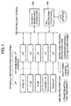
- the architecture of a multiplexing system based on the present invention incorporates a functional separation of line related functions and protocol related functions.
- a functional separation is accomplished by physically separating a set of line interface card (LIF) from a universal interface card (UIF) through a frame-based interface 101 that will be described later. All line related functions are done at the LIF while all higher level protocol related processing is done at the UIF.
- LIF line interface card
- UIF universal interface card
- All the UIFs are of the same type, while the structure of LIFs depend on the type of line technology used. The number of different LIFs that are provided depends on the technology available. Here, the followings may be included: T1 LIF, T3 LIF, Asymmetric Digital Subscriber Line (ADSL) LIF (CAP/DMT), HDSL LIF, ADSL-lite LIF, Ethernet LIF, Radio LIFs, 25Mb/s ATM LIF, and Cable Modem LIF.
- the Radio LIFs include global system for mobile communications (GSM), code division multiple access (CDMA), Wireless ATM, etc.
- UIF Universal Test and Operation Interface for ATM
- PCI Peripheral Component Interconnect
- All protocol processing is performed in the UIFs which converts frames to ATM cells before passing them to a cell multiplexer card 104 in the upstream direction and vice versa in the down stream direction through an ATM cell bus 102 or UTOPIA.
- the cell multiplexer card 104 receives ATM cells from an ATM network and passes them to the UIF through the ATM cell bus 102. At the UIF, the received ATM cells are converted to frames and they are then passed to the LIF through the frame-based interface 101. Finally, they are converted to suit appropriate line technologies.
- the respective LIFs are connected to UIFs. It should be noted that several instances of UIFs are used but they are all of the same type.
- the UIFs, an element manager card 103 and the cell multiplexer card 104 are connected to each other through the ATM cell bus 102 or UTOPIA.
- the element manager card 103 and the cell multiplexer card 104 will be described in detail later.
- An advantage of this architecture is that customers can buy multiplexers without deciding the exact mix of line cards that need to be deployed. Furthermore, as the demand grows, customers can add and delete line interface cards and the system will auto-configure itself based on the changes.
- the mix of services being offered by such an architecture is also completely programmable and flexible.
- the mechanical arrangement of a platform embodying the present invention also allows for a stackable architecture allowing line interface cards and their corresponding modules to be added to the system in a modular fashion.
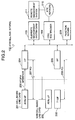
- a cell-based line card (ADSL LIF) 201 and a non-cell-based line card (ADSL LIF) 202 are connected to a UIF 204, and a T1 LIF 203 is connected to a UIF 205.
- the UIF is designed to have two kinds of interfaces to couple with the LIF. These are the industry standard UTOPIA interface for a cell-based line card and a PCI interface for non cell-based line cards.
- the PCI bus also serves as a computer bus for interconnecting LIF processor with UIF processors.
- the cell-based ADSL LIF 201 is connected to the UIF 204 through both a UTOPIA interface 206 for transfer of ATM-based cells and a PCI interface 207 for transfer of non ATM-based data.
- the non-cell-based ADSL LIF 202 is connected to the UIF 204.
- the T1 LIF 203 is connected to the UIF 205 through a PCI interface 208.
- the element management system card 103, the cell multiplexer 104, and a function server 209 are attached to the ATM cell bus 102 or UTOPIA.
- the cell multiplexer 104 is connected to an ATM network 210.
- the element management system card 103 can be remotely managed using the remote management system 211.
- the PCI bus standard is augmented to provide hot-swapping capability by using the compact PCI standard with special tristate-able line drivers using the Texas Instruments LVTH family.
- the features of this logic family that is important for the present invention are:
- the flexible universal access multiplexing system is organized in a hierarchical fashion.
- the element management system card 103 which maintains a master copy of all databases and memory-maps communicates with the UIF CPUs through the ATM cell bus using a dedicated PVC for interprocessor communications.
- the UIF CPU in turn communicates with individual LIF CPUs through the PCI interface so as not to reduce the UIF performance.
- the cell-based ADSL LIF 201 When the cell-based ADSL LIF 201 is inserted and connected to the UIF 204, the cell-based ADSL LIF 201 is set to an operable state such that ATM-based cells are allowed to be transferred through the UTOPIA interface 206 between them. Then the non-cell-based ADSL LIF 202 is inserted and connected to the UIF 204, the non-cell-based ADSL LIF 202 is set to an operable state such that non ATM-based data are allowed to be transferred between them through the PCI interface 207. As described before, the PCI interface 207 is also used as a computer bus to interconnect two processors of the LIFs 201 and 202 with the processor of the UIF 204.
- the PCI interface 208 is also used as a computer bus to interconnect the processor of the LIF 203 with the processor of the UIF 205.
- a set of messages is used to communicate between a LIF and a UIF.
- a cell-based ADSL LIF has up to eight physical media dependent (PMD) components including Transmit and Receive. Five of these PMD1-PMD5 are shown in the figure.
- the PMD components PMD1-PMD5 are connected to ADSL EOC/AOC registers 302 and also to a Utopia bus 206 which is connected to a Utopia arbitor 306.
- An LIF PCI bus 301 connects the ADSL EOC/AOC registers 302, an LIF CPU 303, a memory 304, and a PCI bridge chip 305.
- the basic functions performed on this LIF are:
- the LIF CPU 303 communicates with the UIF through the PCI bus 301 and the PCI bridge chip 305.
- the present embodiment uses a Rate Adaptive DSL (RADSL).
- the LIF CPU 303 manages the embedded operations channel (EOC) channels on each line as well as the ADSL overhead channel (AOC). Since the ADSL transmission unit-central office (ATU-C) is expected to be the master in the ANSI specification (T1.413), the ADSL transmission unit-remote (ATU-R) state machines are managed and monitored by the digital subscriber link access multiplexer (DSLAM) using EOC messages.
- DSL transmission unit-remote (ATU-R) state machines are managed and monitored by the digital subscriber link access multiplexer (DSLAM) using EOC messages.
- the LIF CPU 303 also manages the AOC bits in the ADSL frame which includes configuration and bit swapping information between the ATU-R and ATU-C.
- DRA dynamic rate adaptation
- a memory interface is maintained between the two CPUs, LIF CPU 303 and UIF CPU, through the PCI bus 207.
- Adding/deleting bandwidth to a given VC implies adding/deleting bandwidth to a given ASX channel on the ADSL line. This in turn may trigger a Dynamic Rate Adaptation procedure between the ATU-R and the ATU-C which has to be managed by the LIF CPU 303.
- ABR bit rate
- Every rate change should not trigger a DRA and every DRA (induced by line conditions for example) should not change the UPC parameters. At least a 32 Kb/s rate change granularity needs to be maintained but even this may be excessive.
- a line condition based rate change should let the LIF CPU 303 inform the UIF CPU of the changes and let the UIF CPU rearrange the bandwidth on the individual VCs.
- a change in UPC parameters or ABR rates at the VC level should be managed by the UIF CPU which informs the LIF CPU 303 of the necessary changes.
- the actual DRA procedure between the ADSL transmission unit - remote (ATU-R) and the ADSL transmission unit - central office (ATU-C) is initiated by the LIF CPU 303.
- the mapping of VCs to ADSL subchannels is maintained by the UIF CPU as the LIF CPU 303 does not have any knowledge of VCs.
- the LIF Memory 304 contains a table that maintains the rate on each subchannel on each ADSL line. The table is read and written by both LIF CPU 303 and UIF CPU through the PCI bus.
- Line management signals between the ATU-R and ATU-C is communicated using either EOC/AOC channels or by using embedded ATM OAM Cells. Since ATM is terminated at the UIF and not the LIF, the UIF CPU processes the OAM cells and passes either the entire cell or makes a function call to the LIF CPU 303 to initiate the proper action.
- the first approach is simpler and does not involve distributed multiprocessing problems, but this approach pays the penalty of multihops through the CPUs. Since the PCI bus is a broadband bus, this may not be a problem.
- a critical component of how many ADSL physical media dependents (PMDs) that an LIF can support is related to the amount of power the ADSL modems consume.
- PMDs physical media dependents
- Initial estimates show CAP-based modem chips consuming close to 4W and DMT chips consuming about 10W.
- innovative power management schemes are needed at the LIF to maximize line density and minimize power.
- One scheme is to use the modem pooling technique, which allows multiple ADSL lines to reuse the same digital chips. This is done by inserting an analog crossbar switch between the analog front end and the digital backend that performs the signal processing.
- an ADSL LIF with a modem bank Multiple ADSL lines are connected through analog front ends 401 and tone detectors 402 to an analog crossbar switch 403 which is controlled by a switch controller 404 depending on tone detection signals received from tone detectors 402.
- the crossbar switch 403 is used to statistically multiplex the multiplex ADSL lines to a modem bank that performs all the digital operation.
- ADSL transceivers 405 are connected to the Utopia 206 through Cell TCs 406.
- the ADSL transceivers 405 are also connected to an ADSL EOC/AOC PCI interface 407 through which a LIF CPU 408 controls the ADSL transceivers 405.
- an ADSL modem is a combination of an analog front end 401 and an ADSL transceiver 405.
- the LIF CPU 408 statistically multiplexing the multiple lines to the modem bank needs to be done by the LIF CPU 408. This involves maintaining the ADSL specific states (equalizer settings, SNR calculations, channel analysis as well as ADSL state machines) on a per line basis in memory 409 and downloading the correct state into the modem pool when the appropriate line is connected to the modem. The switching occurs under the control of the switch controller 404. Sleep mode operation is also possible between the ATU-R and ATU-C in this setup. Note that the tone detector 402 looks for the R-ACT-REQ tone from the ATU-R to enable operations (34.5 KHz tone with a certain timing pattern). The ATU-C will now block if all the modems at the ATU-C are in service. A continuous pattern of idle flags on the embedded operations channel/ADSL operation channel (EOC/AOC) will be used by the LIF CPU 408 to tear down a connection through the analog crossbar switch 403.
- EOC/AOC embedded operations channel/ADSL operation channel
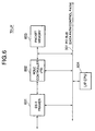
- a T1 LIF supports 32 T1 lines attached to Quad T1 Line Interface Units (LIUs) 501 which are in turn connected to a 32-channel HDLC controller 503 through Octet T1 Framers 502, respectively.
- a packet memory 504 is connected to the HDLC controller 503.
- the Quad T1 LIUs 501 and the Octet T1 Framers 502 are attached to the PCI bus 301.
- the Octet T1 Framers 502 perform framing (including superframe and extended super frame), line coding, robbed bit signalling and alarm statistics gathering.
- the 32-channel HDLC controller 503 performs flag delineation, bit stuffing, CRC verification and length checking, time slot interchange, and transparent mode DS0 coupled with HDLS DS0. Packets are transferred through the PCI bus 301 to and from the UIF.
- a LIF CPU 505 is connected to the PCI bus 301 to control the above components to implement the following functions.
- the T3 LIF supports one T3 channel. Again both channelized and unchannelized mode DS-3 are supported. Hardware support for HDLC bitstuffing and destuffing to delimit valid frames is supported.
- a T3 LIF in an unchannelized DS-3 mode is connected to an HDLC controller 602 which is connected to a packet memory 603.
- the DS-3 framer 601, the HDLC controller 602 and the packet memory 603 are connected to the PCI bus 301 which is connected to an LIF CPU 604. Packets are transferred through the PCI bus 301 to and from the UIF.
- a LIF CPU 604 controls the above components to implement the following functions.
- the Ethernet LIF is expected to terminate the Ethernet media access control (MAC) protocol.
- MAC media access control
- the 10BaseT card supports up to eight ethernet slots.
- MACs 701 are attached to a PCI bus 301.
- MAC tables 702 and an LIF CPU 703 are also attached to the PCI bus 301.
- GSM global switching for mobiles
- the UIF also provides SS7 support.
- the LIF is capable of extracting the slow associated control channel (SACCH) information from the traffic channels in the time division multiplex access (TDMA) frames.
- SACCH slow associated control channel
- the LIF also performs internal HO, i.e., time-slot switching and BTS switching.
- the LIF and the UIF coordinate and handle the following control channels:
- the UIF plays a role in communication management and call control.
- the OC-3 LIF terminates SONET framing and provides either channelized or unchannelized data to the UIF. This enables STM traffic to be brought into the access multiplexer which can then be converted to ATM. IP over SONET can be efficiently carried in this arrangement wherein SONET is terminated as the LIF and IP packets are passed to the UIF using time slot channelization information the IP termination is done on the UIF from where it is transmitted to the network using a variety of IP over ATM schemes.
- the LIF also provides support for SONET ADM capability.
- the flexible universal access multiplexer As described before, the flexible universal access multiplexer according to the present invention is provided with the following capabilities:
- a UIF is physically separated from an LIF to provide a functional separation between line related functions performed by the LIF and higher layer protocol related functions performed by the UIF. It should be noted that all UIFs are of same type while all LIFs may be of different types as described in Figs. 3-7.
- the UIF is provided with a Utopia interface 801 which can be connected to a cell-based LIF through the UTOPIA 206.
- the Utopia interface 801 is connected to a cell memory 802 and a header translation table 803.
- the UIF includes a cell scheduler 804, a Segmentation and Reassembly (SAR) section 805, and a packet memory 806.
- SAR Segmentation and Reassembly
- Packets received from frame-based LIFs through the PCI bus are stored in the packet memory 806.
- the SAR section 805 segments the packets stored in the packet memory 806 into cells and stores the cells onto the cell memory 802. Conversely, cells received from the ATM cell bus 102 are stored onto the cell memory 802. Then, the SAR section 805 reassembles packets from the received cells and the packets are transferred to the frame-based LIFs through the PCI bus.
- outgoing and incoming cells are transferred through the Utopia interface 801.
- the header translation table 803 provides necessary information to determine the outgoing VPI/VCI for the cells coming in through the cell-based Utopia interface 801 or through another Utopia interface 810. These operations are controlled by a UIF CPU 807 using Integrated Local Management Interface per VC Accounting section 808 and packet support tables 809.
- the UIF When the LIF is plugged into the PCI slot of the UIF, the UIF autoconfigures the LIF.
- the UIF obtains the following information from the LIF:
- the signaling referred to here is not the traditional signaling associated with call setup and teardown but signaling related to associating a protocol stack with a given ATM VC.
- the signaling mechanism can be explicit or implicit.
- explicit signaling a well-know channel on the LIF/CPE link carries these messages while in the implicit case, channels (VCs/DLCIs/Slots) are partitioned to different protocol stacks. This channel partitioning is negotiated using Hello messages between the LIF and the CPE.
- a signaling channel is specified on the link between the CPE and the LIF. If the link supports ATM, then a PVC is used to carry the protocol specific information between the CPE and the Mutiplexer.
- a similar signaling channel can also be carved out of a T1 link by using the robbed bit signaling channel or a FR PVC or the D channel on a PRI and using the user specific PID.
- the signaling message carries information on the protocol to be used and will carry a protocol id field in it.
- the LIF needs to store the signaling messages in a specific address location on its packet memory and inform the UIF about the location when it is plugged in.
- the signaling message is extracted by the LIF and passed to the UIF using the aforementioned signaling location.
- the UIF terminates the signaling and translates it to the relevant signaling format for further transmission down the network based on the protocol stack that is relevant for the VC.
- the UIF performs all the ATM level functions. This includes cell scheduling as well as per VC queuing performed by the cell scheduler 804. Multiclass support is assumed so the UIF terminates available bit rate (ABR) and processes resource management (RN) cells. Scheduling algorithm such as weighted round robin or strict priority or deadline scheduling is programmable. Packet level support performed by the Packet Support Tables 809 includes per flow queuing as well as various packet discard schemes ⁇ early packet discard (EPD), partial packet discard (PPD), random early discard (RED) ⁇ .
- EPD early packet discard
- PPD partial packet discard
- RED random early discard
- Shaping and policing functions are also performed.
- VC merge is an optional feature that needs hardware support for packet based scheduling.
- the SAR functions will also provide multi AAL support (AAL5, AAL1 and AAL2) for the different application types. This information needs to be provided on a per VC basis during the autoconfiguration stage or can be updated as VCs are set up on a call by call basis.
- the protocol stacks listed above is supported on the UIF in a modular downloadable fashion.
- the entire ATM signaling stack (UNI 4.0, PNNI 1.0) is downloaded on the UIF if needed.
- the IP protocol stack ⁇ internet gateway management protocol (IGMP), internet control management protocol (ICMP), resource reservation protocol (RSVP), border gateway protocol (BGP), open switch path first (OSPF), RIP, distance vector multicast routing (DVMRP) etc. ⁇ is downloaded on the UIF CPU 807 or kept on a separate function server card 209.
- a modest size IP table look up cache 809 is maintained on the UIF CPU 807.
- Flow id tables can be carved out from the system memory if IP switching schemes based protocol stacks are being used on a given UIF.
- the L3/L2 binding hardware is supported on the UIF. This takes a L3 address and pops out a L2 VC for that given address.
- the same hardware could be used for MPOA and other IP switching schemes. Based on the MPLS requirements, a 20-bit lookup table may be needed on the UIF.
- the UIF is also expected to support remote Jave/Corba agents from remote agents.
- the typical functions that these agents need to perform are:
- the UIF maintains a copy of the interim link management interface (ILMI) and the ATMMIB database 808. Other database support for IP switching schemes is also supported.
- the UIF allows both simple network management protocol (SNMP) and common management information protocol (CMIP) agents to query these databases.
- SNMP simple network management protocol
- CMIP common management information protocol
- the elements management system card 103 is the master controller of the universal access multiplexer.
- a CORBA ORB will resides on this card. This card maintains master copies of all the databases as well as configuration and billing information.
- the element management card communicates with the UIFs using ATM PVCs. It also has CORBA-based PVC setup with remote network servers and databases.
- the elements management system (EMS) is expected to be carrier-ready and needs to support TMN interfaces to Operation Support Systems. It needs an X.25 interface to provide support for SS7 (Signaling System 7)-based systems.
- the cell multiplexer 104 provides the trunk side interface to the central office.
- the cell multiplexer 104 is provided with a Utopia interface 901 connected to the ATM cell bus 102.
- the Utopia interface 901 is connected to a cell memory 902 and a header translation table 903.
- the cell multiplexer 104 further includes a cell scheduler 904 and an ATM/SONET physical interface 905.
- the ATM/SONET physical interface 905 provides the hardware interface to the trunk on the uplink side.
- the cell multiplexer 104 is powered by a powerful RISC processor 906.
- NNI support (broadband inter carrier interface (BICI), broadband ISDN user path (BISUP), private NNI(PNNI)) is provided here.
- BICI broadband inter carrier interface
- BIOSUP broadband ISDN user path
- PNNI private NNI
- Layer 3 processing is offloaded to the function server card 209. This allows IP route lookups in case of cache misses as well as MPOA client function and some of the IP switching functions to be performed here. PNNI is also supported here.
- the LIF when a LIF is plugged into a UIF, the LIF makes a registration request to the elements management system (EMS) card 103.
- EMS elements management system
- the LIF When receiving the registration response from the EMS card 103, the LIF makes a registration request to the UIF using a Hello message as will be described later.
- the UIF determines whether the connected LIF is acceptable or not in response to the registration request and sends the result (accept or reject) to the LIF. If the LIF is acceptable, the UIF sends the LIF a configuration message conveying the correct configuration files to support the LIF, which have been downloaded from the EMS card 103.
- the LIF On successful completion of the configuration, the LIF sends a configuration success/failure message back to the UIF.
- the UIF identifies the remote CPE using line stabilization, identify remote and identify remote acknowledgement messages as will be described later and then sends a loopback message to the LIF.
- the loopback message causes the LIF to set up the loopback test.
- the LIF sends an acknowledgement of the loopback message to the UIF and starts measurement.
- the collected statistics are sent by the LIF to the UIF in response to the request of the UIF. The statistics are reported to the UIF at predetermined intervals (here, every 1 second).
- All the messages that are exchanged between the LIF and the UIF have the same format.
- Each message has a header followed by the contents of the message.
- the header has an LIF identifier and the message type.
- the message content is a variable number of data fields. The exact number of the data fields and their contents depends on the message header.
- FIG. 11 an example of a general format for a message is shown.
- the present invention is not limited to any specific number of bytes allocated for each of the fields.
- the LIF ID is further classified into sub-fields namely PHY ID and the Protocol ID.
- the PHY ID is typically one of:
- the Protocol ID specifies whether the data path is cell-based or frame-based (UTOPIA or PCI).
- a line specific protocol sub ID is also provided.
- the protocol sub ID can be used to specify the line ID, line coding (DMT, CAP, QAM) and line type (FAST, INTERLEAVED etc.).
- the number of lines that are being supported on the line card is also conveyed in the LIF ID.
- LIF Sub-ID field looks like as shown in Fig. 12.
- Line # field A special code point needs to be defined on the Line # field to indicate it applies to all lines on an LIF.
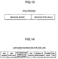
- a hello message is the first message that is sent by the LIF to the UIF. This message is common for all LIFs.
- the Hello message conveys the LIF ID to the UIF and enables the UIF to download the correct configuration files to support the LIF from the element management card.
- the configuration message will vary from LIF to LIF but typically contains provisioning information that needs to be loaded onto the LIF tables to make the LIF operational.
- Fig. 14 shows the typical configuration message that one may see for an ADSL LIF and Fig. 15 shows the configuration message for the T1 line card on the other hand.
- one more level of CFG message (D53, DS 1, DSO etc) is provided.
- the UIF downloads this information to the LIF from an NMS entity before the LIF can start a dialogue with the remote. Hence the time to download these messages to the LIF is critical.
- the LIF On successful completion of the channel activation or initialization procedure, the LIF sends this message to the UIF. This is an indication to the UIF that the LIF has established the link with the remote and it is ready to perform measurements both at the local and the remote ends. Only after this message is received can the UIF issue any following messages. The format of this message will vary from LIF to LIF but for the ADSL LIF.
- Fig. 17 an example for the line stabilization message format is shown.
- the data field types, SNR margins etc. are all the fields that have been agreed upon between the local and the remote during the channel initialization and activation phase.
- Fig. 18 an example of the Identify Remote massege is shown.
- the UIF requests details about a remote using this message. This message does not have any data fields except the line number on the LIF.
- Identify Remote acknowledgement message An example of the Identify Remote acknowledgement message is shown. It is assumed that the LIF maintains a local copy of the remote's identity. If not it shall probe the remote and get the identity. The LIF passes this identity information in this message.
- Fig. 20 an example of this message is shown. This message allows the UIF the means to reset a remote. It is assumed that the LIF has the ability command a remote reset. This message does not have any data fields except for the line card number on the LIF.
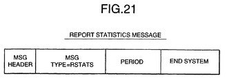
- Fig. 21 an example of the report statistics message is shown.
- the UIF requests collected statistics of the local and remote from the LIF through this message.
- the period refers to the time period of interest over which statistics are to be collected. The granularity of this period is predetermined.
- the End System refers to whether the UIF desires local or remote statistics.
- Fig. 22 the format for the ADSL LIF report statistics acknowledgement message is shown.
- the LIF maintains statistics of the local and remote end measured over specific intervals.
- the format will vary from LIF to LIF.
- Fig. 23 an example of the loopback message is shown.
- the UIF can initiate loopback tests between the LIF and the remote.
- the loopback tests can be at various levels (F3, F4, F5 etc.).
- the UIF can initiate a loopback procedure all the way up to the remote (CPE) through the LIF.
- the procedure is started by the Loopback message.
- the 'Scope' above defines the point at which the loopback should occur.
- 'Set' initiates a loopback and 'Reset' terminates it.
- Explicit backoff messages between the LIF and the UIF in order to minimize buffer overflows on the packet memory is provided.
- the details of the messages depends on the specific flow control mechanism between the LIF and the CPE.
- a simple XON/XOFF flow control mechanism will be effective for the Ethernet line card.
- the mechanism for message exchange between the UIF and the Elements Manager is probably going to be procedure calls using either remote procedure call (RPC) or some form of interprocess communication (IPC).
- RPC remote procedure call
- IPC interprocess communication
Landscapes
- Engineering & Computer Science (AREA)
- Computer Networks & Wireless Communication (AREA)
- Data Exchanges In Wide-Area Networks (AREA)
Applications Claiming Priority (6)
| Application Number | Priority Date | Filing Date | Title |
|---|---|---|---|
| US185592 | 1988-04-25 | ||
| US9419798P | 1998-07-27 | 1998-07-27 | |
| US94197P | 1998-07-27 | ||
| US18464098A | 1998-11-03 | 1998-11-03 | |
| US184640 | 1998-11-03 | ||
| US09/185,592 US6125116A (en) | 1998-07-27 | 1998-11-04 | Message sets for a flexible programmable ATM access multiplexer using functional separation of line and protocol related functions |
Publications (1)
| Publication Number | Publication Date |
|---|---|
| EP0977456A2 true EP0977456A2 (de) | 2000-02-02 |
Family
ID=27377704
Family Applications (1)
| Application Number | Title | Priority Date | Filing Date |
|---|---|---|---|
| EP19990111946 Withdrawn EP0977456A2 (de) | 1998-07-27 | 1999-06-23 | Multiplexsystem und entsprechendes Steuerungsverfahren |
Country Status (4)
| Country | Link |
|---|---|
| EP (1) | EP0977456A2 (de) |
| JP (1) | JP2000049825A (de) |
| AU (1) | AU4104899A (de) |
| CA (1) | CA2276274A1 (de) |
Cited By (12)
| Publication number | Priority date | Publication date | Assignee | Title |
|---|---|---|---|---|
| WO2001082534A1 (en) * | 2000-04-20 | 2001-11-01 | University Of Surrey | Wireless atm network |
| US7080161B2 (en) | 2000-10-17 | 2006-07-18 | Avaya Technology Corp. | Routing information exchange |
| US7330471B2 (en) * | 2001-11-29 | 2008-02-12 | Samsung Electronics Co., Ltd. | Multi digital subscriber line access multiplexor system |
| US7336613B2 (en) | 2000-10-17 | 2008-02-26 | Avaya Technology Corp. | Method and apparatus for the assessment and optimization of network traffic |
| US7349994B2 (en) | 2000-10-17 | 2008-03-25 | Avaya Technology Corp. | Method and apparatus for coordinating routing parameters via a back-channel communication medium |
| US7363367B2 (en) | 2000-10-17 | 2008-04-22 | Avaya Technology Corp. | Systems and methods for robust, real-time measurement of network performance |
| US7406539B2 (en) | 2000-10-17 | 2008-07-29 | Avaya Technology Corp. | Method and apparatus for performance and cost optimization in an internetwork |
| US7487237B2 (en) | 2000-10-17 | 2009-02-03 | Avaya Technology Corp. | Load optimization |
| US7720959B2 (en) | 2000-10-17 | 2010-05-18 | Avaya Inc. | Method and apparatus for characterizing the quality of a network path |
| US7756032B2 (en) | 2000-10-17 | 2010-07-13 | Avaya Inc. | Method and apparatus for communicating data within measurement traffic |
| US7773536B2 (en) | 2000-10-17 | 2010-08-10 | Avaya Inc. | Method and apparatus for the assessment and optimization of network traffic |
| US7840704B2 (en) | 2000-10-17 | 2010-11-23 | Avaya Inc. | Method and apparatus for performance and cost optimization in an internetwork |
Families Citing this family (2)
| Publication number | Priority date | Publication date | Assignee | Title |
|---|---|---|---|---|
| US6714556B1 (en) * | 2000-07-17 | 2004-03-30 | Advanced Micro Devices, Inc. | In-band management of a stacked group of switches by a single CPU |
| EP2033368A2 (de) * | 2006-05-01 | 2009-03-11 | Adaptive Spectrum and Signal Alignment, Inc. | Verfahren und vorrichtung zur kombination von daten aus mehreren quellen zur charakterisierung von kommunikationssystemen |
-
1999
- 1999-06-22 JP JP17578199A patent/JP2000049825A/ja active Pending
- 1999-06-23 CA CA 2276274 patent/CA2276274A1/en not_active Abandoned
- 1999-06-23 EP EP19990111946 patent/EP0977456A2/de not_active Withdrawn
- 1999-07-22 AU AU41048/99A patent/AU4104899A/en not_active Withdrawn
Cited By (14)
| Publication number | Priority date | Publication date | Assignee | Title |
|---|---|---|---|---|
| WO2001082534A1 (en) * | 2000-04-20 | 2001-11-01 | University Of Surrey | Wireless atm network |
| US7406539B2 (en) | 2000-10-17 | 2008-07-29 | Avaya Technology Corp. | Method and apparatus for performance and cost optimization in an internetwork |
| US7336613B2 (en) | 2000-10-17 | 2008-02-26 | Avaya Technology Corp. | Method and apparatus for the assessment and optimization of network traffic |
| US7349994B2 (en) | 2000-10-17 | 2008-03-25 | Avaya Technology Corp. | Method and apparatus for coordinating routing parameters via a back-channel communication medium |
| US7363367B2 (en) | 2000-10-17 | 2008-04-22 | Avaya Technology Corp. | Systems and methods for robust, real-time measurement of network performance |
| US7080161B2 (en) | 2000-10-17 | 2006-07-18 | Avaya Technology Corp. | Routing information exchange |
| US7487237B2 (en) | 2000-10-17 | 2009-02-03 | Avaya Technology Corp. | Load optimization |
| US7675868B2 (en) | 2000-10-17 | 2010-03-09 | Avaya Inc. | Method and apparatus for coordinating routing parameters via a back-channel communication medium |
| US7720959B2 (en) | 2000-10-17 | 2010-05-18 | Avaya Inc. | Method and apparatus for characterizing the quality of a network path |
| US7756032B2 (en) | 2000-10-17 | 2010-07-13 | Avaya Inc. | Method and apparatus for communicating data within measurement traffic |
| US7773536B2 (en) | 2000-10-17 | 2010-08-10 | Avaya Inc. | Method and apparatus for the assessment and optimization of network traffic |
| US7840704B2 (en) | 2000-10-17 | 2010-11-23 | Avaya Inc. | Method and apparatus for performance and cost optimization in an internetwork |
| US7330471B2 (en) * | 2001-11-29 | 2008-02-12 | Samsung Electronics Co., Ltd. | Multi digital subscriber line access multiplexor system |
| US8023421B2 (en) | 2002-07-25 | 2011-09-20 | Avaya Inc. | Method and apparatus for the assessment and optimization of network traffic |
Also Published As
| Publication number | Publication date |
|---|---|
| JP2000049825A (ja) | 2000-02-18 |
| CA2276274A1 (en) | 2000-01-27 |
| AU4104899A (en) | 2000-02-17 |
Similar Documents
| Publication | Publication Date | Title |
|---|---|---|
| US6597689B1 (en) | SVC signaling system and method | |
| US6529479B1 (en) | SVC accessing method for use in ATM-DSLAM | |
| US6407992B1 (en) | Multiplexing terminals in a distributed network | |
| US6396837B1 (en) | Method and system for mapping virtual connections to asymmetric digital subscriber line latency paths | |
| EP0977456A2 (de) | Multiplexsystem und entsprechendes Steuerungsverfahren | |
| WO2000076265A1 (en) | Partitioning of shared resources among closed user groups in a network access device | |
| US20020034162A1 (en) | Technique for implementing fractional interval times for fine granularity bandwidth allocation | |
| US6032272A (en) | Method and apparatus for performing packet based policing | |
| US6718419B1 (en) | System and method for extending the number of addressable physical devices on a data bus | |
| JP2001298481A (ja) | 通信制御方法、通信制御装置および記録媒体 | |
| US20020059426A1 (en) | Technique for assigning schedule resources to multiple ports in correct proportions | |
| US8077728B2 (en) | Substitution call control system in a communication network | |
| US6714516B1 (en) | Congestion control mechanism for SSCOP protocol | |
| Perros | An introduction to ATM networks | |
| WO2000011880A2 (en) | Common access platform | |
| US6952420B1 (en) | System and method for polling devices in a network system | |
| AU4011299A (en) | Open control system an VPN creation method for multiprotocol ATM switches | |
| US6125116A (en) | Message sets for a flexible programmable ATM access multiplexer using functional separation of line and protocol related functions | |
| US6665302B2 (en) | Method and system for handling a loop back connection using a priority unspecified bit rate in ADSL interface | |
| Sun | ATM and B-ISDN | |
| Kim et al. | An implementation of inter processor communication for narrowband network interworking in ATM switching system | |
| Killat | Connectionless service in an atm‐based network | |
| van de Meulenhof et al. | Technische Universiteit tlî) Eindhoven | |
| Gauthier | Congestion control strategies for broadband ISDN | |
| KR20020055956A (ko) | 에이티엠 인터페이스 장치의 자원관리 방법 |
Legal Events
| Date | Code | Title | Description |
|---|---|---|---|
| PUAI | Public reference made under article 153(3) epc to a published international application that has entered the european phase |
Free format text: ORIGINAL CODE: 0009012 |
|
| AK | Designated contracting states |
Kind code of ref document: A2 Designated state(s): AT BE CH CY DE DK ES FI FR GB GR IE IT LI LU MC NL PT SE |
|
| AX | Request for extension of the european patent |
Free format text: AL;LT;LV;MK;RO;SI |
|
| RAP1 | Party data changed (applicant data changed or rights of an application transferred) |
Owner name: EULIX NETWORKS, INC. |
|
| STAA | Information on the status of an ep patent application or granted ep patent |
Free format text: STATUS: THE APPLICATION HAS BEEN WITHDRAWN |
|
| 18W | Application withdrawn |
Withdrawal date: 20010710 |