EP0977464A2 - Tonsignalverarbeitungsschaltung - Google Patents
Tonsignalverarbeitungsschaltung Download PDFInfo
- Publication number
- EP0977464A2 EP0977464A2 EP99306038A EP99306038A EP0977464A2 EP 0977464 A2 EP0977464 A2 EP 0977464A2 EP 99306038 A EP99306038 A EP 99306038A EP 99306038 A EP99306038 A EP 99306038A EP 0977464 A2 EP0977464 A2 EP 0977464A2
- Authority
- EP
- European Patent Office
- Prior art keywords
- filter
- phase difference
- channel signal
- signal
- surround
- Prior art date
- Legal status (The legal status is an assumption and is not a legal conclusion. Google has not performed a legal analysis and makes no representation as to the accuracy of the status listed.)
- Granted
Links
Images


Classifications
-
- H—ELECTRICITY
- H04—ELECTRIC COMMUNICATION TECHNIQUE
- H04S—STEREOPHONIC SYSTEMS
- H04S3/00—Systems employing more than two channels, e.g. quadraphonic
- H04S3/002—Non-adaptive circuits, e.g. manually adjustable or static, for enhancing the sound image or the spatial distribution
-
- H—ELECTRICITY
- H04—ELECTRIC COMMUNICATION TECHNIQUE
- H04S—STEREOPHONIC SYSTEMS
- H04S1/00—Two-channel systems
- H04S1/002—Non-adaptive circuits, e.g. manually adjustable or static, for enhancing the sound image or the spatial distribution
-
- H—ELECTRICITY
- H04—ELECTRIC COMMUNICATION TECHNIQUE
- H04S—STEREOPHONIC SYSTEMS
- H04S1/00—Two-channel systems
- H04S1/007—Two-channel systems in which the audio signals are in digital form
-
- H—ELECTRICITY
- H04—ELECTRIC COMMUNICATION TECHNIQUE
- H04S—STEREOPHONIC SYSTEMS
- H04S2400/00—Details of stereophonic systems covered by H04S but not provided for in its groups
- H04S2400/01—Multi-channel, i.e. more than two input channels, sound reproduction with two speakers wherein the multi-channel information is substantially preserved
Definitions
- the present invention relates to an audio signal processing circuit in a so-called surround system. More particularly, the present invention relates to simplification of its structure, improvement of accuracy, and localization of sound image.
- an audio reproduction apparatus having surround channels at a left and a right sides to a listener in addition to a left and a right (and optionally a center) front channels, has been developed not only for business use but also for home use.
- two of surround speakers are usually arranged at the both sides (i.e., left and right sides) to the listener.
- the correlation between the left and the right surround signals is small (i.e., when a stereophonic surround system is employed)
- the listener does not have an unnatural feeling.
- the correlation between the left and the right surround signals is large (i.e., when a monophonic surround system is employed)
- the following problem is recognized depending on the listener's position. Specifically, when the listener is positioned at the center between the left and the right surround speakers, the listener has an unnatural feeling as if sound image was localized in the head of the listener.
- a technique alternatively dividing a monophonic signal into two channels with respect to each frequency component of predetermined width by using a comb type filter so as to virtually reproduce stereophonic sound, a technique performing a pitch shift processing so as to reduce the correlation (e.g., THX system), and a technique performing a 90 degrees phase shift processing so as to make the correlation zero, have been proposed.
- the technique performing the 90 degrees phase shift processing is superior to the above-described techniques in view of the fact that the sound quality is not lowered in the case of the stereophonic surround signals and that a change of a processing mode is not required.
- sound image is apt to be localized in the direction of the channel whose phase relatively progresses, which provides the listener with an unnatural feeling. This problem is especially remarkable in the case where the left and the right surround sound sources are virtual sound sources.
- an apparatus and a method which are capable of performing the same processing independent of whether the surround signals are monophonic or stereophonic, preventing sound image localization in the head of the listener so as to create sound field just as enveloping the listener, and performing a processing which does not compromise the sound quality even when the surround signals are stereophonic, are eagerly demanded.
- an audio signal processing circuit disclosed in Japanese Laid-open Publication No. Hei 8-265899 (265899/1996) is shown in Figure 29 .
- the circuit is used for making a listener 102 to feel that sound image reproduced by virtual speakers XL and XR is virtually localized at rear sides to the listener 102 .
- the listener is able to feel that he/she is surrounded by the sound reproduced with the speakers 104L and 104R as well as surrounded by the sound reproduced with the virtual speakers XL and XR even when the speakers 104L and 104R are actually arranged only in front of the listener 102 .
- h LL is a transfer function from the speaker 104L to the left ear 102L of the listener 102
- h LR is a transfer function from the speaker 104L to the right ear 102R of the listener 102
- h RL is a transfer function from the speaker 104R to the left ear 102L of the listener 102
- h RR is a transfer function from the speaker 104R to the right ear 102R of the listener 102 .
- the cross-talk cancel filter 114 functions to cancel cross-talk from the right speaker 104R to the left ear 102L of the listener and that from the left speaker 104L to the right ear 102R of the listener. Accordingly, the cross-talk cancel filter 114 makes it possible that a left channel signal L reaches only the left ear 102L and a right channel signal R reaches only the right ear 102R . As a result, sound image can be localized at the desired position by adjusting the amount of the cross-talk with the cross-talk cancel filter 114 .
- the above-mentioned cross-talk cancel filter 114 can also be obtained by utilizing the shuffler type filter as shown in Figure 30 .
- the shuffler type filter According to the shuffler type filter, a circuit having satisfactory sound image localization ability or satisfactory cross-talk cancel ability can be obtained only when the filters 110a and 110b are highly accurate.
- the structure thereof becomes complicated.
- DSP digital signal processor
- the structure of the filters is simple, the ability of the filters is insufficient.
- An audio signal processing circuit is used for an audio reproduction apparatus at least having sound source located substantially at left and right sides to a listener.
- the audio signal processing circuit includes a phase difference control portion.
- the phase difference control portion receives a left channel signal for the left sound source and a right channel signal for the right sound source, controls a phase difference between the left and right channel signals so as to produce a relative phase difference in the range of 140 degrees to 160 degrees, and outputs the phase difference controlled left and right channel signals for the left and right sound source, respectively.
- the phase difference of 60 degrees causes the problem that sound image is localized in the direction of the channel whose phase relatively progresses, as in the case of the 90 degrees phase shift processing.
- the phase difference of 180 degrees i.e., inverse phase
- the phase difference of 140 to 160 degrees does not cause an unpleasant feeling unique to the inverse phase or produces sound image localization in the certain direction.
- the present invention can prevent sound image of the monophonic signal from localizing in the head of the listener so as to create sound field just as enveloping the listener.
- the audio reproduction according to the present invention does not compromise the sound quality even when the stereophonic signal is employed.
- the same processing can be performed independent of whether the input signal is monophonic or stereophonic.
- the phase difference control portion produces the relative phase difference of 140 degrees to 160 degrees in a frequency region ranging from 200 Hz to 1 kHz. Accordingly, the phase difference control can be effectively performed while the structure of the phase difference control portion is made simple.
- a surround audio reproduction apparatus having a left and a right channels in front of a listener and a left and a right surround channels at left and right sides with respect to the listener.
- the apparatus includes a phase difference control portion.
- the phase difference control portion receives a left surround channel signal and a right surround channel signal, controls a phase difference between the left and the right surround channel signals so as to produce a relative phase difference in the range of 140 degrees to 160 degrees, and outputs the phase difference controlled surround left and right channel signals for a left and a right surround sound source, respectively.
- an audio reproduction apparatus capable of performing the same processing independent of whether the input signals are monophonic or stereophonic, preventing sound image localization in the head of the listener so as to create sound field just as enveloping the listener, and performing a processing which does not compromise the sound quality even when the surround signals are stereophonic, can be obtained.
- the left and the right surround sound sources are a virtual sound source produced by a sound image localization processing.
- the phase difference control portion produces the relative phase difference of 140 degrees to 160 degrees in a frequency region ranging from 200 Hz to 1 kHz. Accordingly, the phase difference control can be effectively performed while the structure of the phase difference control portion is made simple.
- an audio reproduction method at least utilizing sound source located substantially at left and right sides to a listener.
- the method includes the steps of: controlling a phase difference between a left channel signal for the left sound source and a right channel signal for the right sound source so as to produce a relative phase difference in the range of 140 degrees to 160 degrees; and outputting the phase difference controlled left and right channel signals for the left and right sound source, respectively.
- a shuffler type audio signal processing circuit includes a first filter for producing a sum signal of a left channel signal and a right channel signal; and a second filter for producing a differential signal of the left channel signal and the right channel signal.
- a gain of the second filter is higher than that of the first filter in a low frequency region. Accordingly, by making an accuracy of the second filter higher than that of the first filter in a low frequency region, the structure of the circuit can be simplified while a reduction of accuracy is prevented.
- a shuffler type audio signal processing circuit includes a first filter for producing a sum signal of a left channel signal and a right channel signal; and a second filter for producing a differential signal of the left channel signal and the right channel signal, wherein the first filter and the second filter are FIR filter, and the tap number of the second filter is larger than that of the first filter. Accordingly, the structure of the circuit can be simplified while a reduction of accuracy is prevented.
- the second filter is composed of a filter bank. Accordingly, a processing margin can be increased by performing down-sampling.
- the filter bank performs down-sampling by the larger number for the lower frequency component. Accordingly, an accuracy of the second filter is made higher than that of the first filter in a low frequency region, so that the structure of the circuit can be simplified while a reduction of accuracy is prevented.
- a shuffler type audio signal processing circuit includes a first filter for producing a sum signal of a left channel signal and a right channel signal; and a second filter for producing a differential signal of the left channel signal and the right channel signal, wherein the first filter is FIR filter and the second filter is composed of a parallel connection of FIR filter and secondary IIR filter. Accordingly, an accuracy of the second filter is made higher than that of the first filter in a low frequency region, so that the structure of the circuit can be simplified while a reduction of accuracy is prevented. Furthermore, since a low frequency component can be processed with the secondary IIR filter, unnecessary increase of the tap number of the FIR filter can be prevented.
- the second filter includes: FIR filter, and secondary IIR filter connected in parallel to the FIR filter at one of the intermediate taps or the end tap thereof. Accordingly, an accuracy of the second filter is made higher than that of the first filter in a low frequency region, so that the structure of the circuit can be simplified while a reduction of accuracy is prevented. Furthermore, by varying an intermediate tap connected to the secondary IIR filter, optimum properties for the filter can be obtained.
- the circuit is used as a cross-talk cancel filter.
- the circuit is used as a sound image localization processing filter.
- a filter includes: FIR filter having a plurality of taps, IIR filter whose input is connected to one of the intermediate taps or the end tap of the FIR filter, and an adding means which adds outputs of the FIR filter and the IIR filter. Accordingly, a filter having desired properties can be obtained.
- a shuffler type audio signal processing method includes the steps of: performing a first filtering process for a sum signal of a left channel signal and a right channel signal; and performing a second filtering process for a differential signal of the left channel signal and the right channel signal, wherein an accuracy of the second filtering process is higher than that of the first filtering process.
- the invention described herein makes the possible the advantages of: (1) providing a processingcapable of performing the same processing independent of whether the input signals are monophonic or stereophonic, preventing sound image localization in the head of the listener so as to create sound field just as enveloping the listener, and performing a processing which does not compromise the sound quality even when the surround signals are stereophonic; and (2) providing a shuffler type filter having a simple structure and a high accuracy.
- Figure 1 is a block diagram of an audio signal processing circuit according to an embodiment of the present invention.
- FIG. 2 is a block diagram of an audio reproduction apparatus wherein the audio signal processing circuit of Figure 1 is incorporated.
- FIGS 3A and 3B are circuit diagrams according to embodiments wherein an all pass filter used in the present invention is composed of an analog circuit.
- Figure 4 is a graph illustrating a frequency-phase relationship of the all pass filter used in the present invention.
- Figure 5 is a schematic view illustrating an arrangement of speakers in accordance with a surround audio reproduction apparatus of the present invention.
- Figure 6 is a block diagram according to an embodiment wherein the audio signal processing circuit of the present invention is applied to a surround audio reproduction apparatus which produces virtual sound sources by a sound image localization processing using DSP.
- Figure 7 is a schematic view illustrating an example of an arrangement of the virtual sound sources of Figure 6 .
- Figure 8 is a signal-flow diagram illustrating the sound image localization processing using DSP.
- Figure 9 is a signal-flow diagram illustrating an embodiment wherein an all pass filter used in the present invention is composed of a secondary IIR filter.
- Figure 10 is a signal-flow diagram according to another embodiment of the present invention.
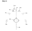
- Figure 11 is a schematic view illustrating an example of an arrangement of the virtual sound sources of Figure 10 .
- Figure 12 is a schematic view of a shuffler type filter according to an embodiment of the present invention.
- Figure 13 is a block diagram illustrating a hardware structure of the audio reproduction apparatus using DSP.
- Figure 14 is a signal-flow diagram illustrating processings carried out by the DSP in accordance with program(s) stored in a memory.
- Figure 15 is a graph illustrating a frequency response H SUM of a first filter and a frequency response H DIF of a second filter, and a cross-talk cancel response Ztl and a cross-talk cancel error Zt2 when the first and the second filters are used, wherein both of the first and the second filters have 32 taps.
- Figure 16 is a graph illustrating H SUM , H DIF , Zt1 and Zt2 wherein both of the first and the second filters have 64 taps.
- Figure 17 is a graph illustrating H SUM , H DIF , Zt1 and Zt2 wherein both of the first and the second filters have 96 taps.
- Figure 18 is a graph illustrating H SUM , H DIF , Zt1 and Zt2 wherein the first filter has 32 taps and the second filter has 96 taps.
- Figure 19 is a signal-flow diagram according to an embodiment using a filter bank.
- Figure 20 is a graph illustrating a cross-talk cancel response Zt1 and a cross-talk cancel error Zt2 when the cross-talk cancel filter shown in Figure 14 is used wherein a first filter having 32 taps and a second filter having 128 taps are incorporated.
- Figure 21 is a graph illustrating a cross-talk cancel response Zt1 and a cross-talk cancel error Zt2 when the cross-talk cancel filter shown in Figure 19 is used wherein a first filter having 32 taps and a second filter corresponding to 128 taps are incorporated.
- Figure 22 is a signal-flow diagram according to an embodiment wherein the second filter 120b is composed of a parallel connection of FIR filter and IIR filter.
- Figure 23 is a graph illustrating a frequency response H SUM of the first filter and a frequency response H DIF of the second filter, and a cross-talk cancel response Zt1 and a cross-talk cancel error Zt2 when the cross-talk cancel filter shown in Figure 22 is used.
- Figure 24 is a signal-flow diagram according to an embodiment wherein an intermediate tap of FIR filter is connected to an input of IIR filter.
- Figure 25 is a graph illustrating a desired impulse response for the second filter.
- Figure 26 is a graph illustrating an impulse response of IIR filter having properties approximate to that of Figure 25 .
- Figure 27 is a graph illustrating a deviation of the impulse response of the IIR filter from the desired impulse response.
- Figure 28 is a graph illustrating an impulse response of FIR filter obtained in due consideration of the deviation of Figure 27 .
- Figure 29 is a schematic view illustrating conventional sound image localization technique.
- Figure 30 is a circuit diagram illustrating shuffler type filter.
- Figure 31 is a block diagram of a sound image localization circuit including a cross-feed filter and a cross-talk cancel filter.
- FIG. 1 is a block diagram of an audio signal processing circuit according to an embodiment of the present invention.
- the audio signal processing circuit includes a phase difference control portion 2 .
- the phase difference control portion 2 receives a left channel signal S L for a left sound source S SL located substantially at a left side to a listener (shown in Figure 5 ) and a right channel signal S R for a right sound source S SR located substantially at a right side to the listener (also shown in Figure 5 ).
- the phase difference control portion 2 controls a phase difference between the left and right channel signals S L and S R so that the relative phase difference be from 140 degrees to 160 degrees (and preferably about 150 degrees) and outputs the phase difference controlled signals S' L and S' R for the left and right sound source, respectively.
- the signals S' L and S' R processed in the above-mentioned manner are respectively supplied to the sound sources S SL and S SR .
- the circuit is capable of preventing sound image localization in the head of the listener and creating sound field just as enveloping the listener.
- the circuit is capable of performing a processing which does not compromise the sound quality (i.e., a feeling that sound image_of the left and the right surround channels is comfortably localized).
- FIG 2 is a block diagram of an audio signal processing circuit 4 which is incorporated into an audio reproduction apparatus, wherein the phase difference control portion 2 includes all pass filters (APFs) 6 and 8 .
- the apparatus includes an amplifier and speakers both of which are connected to the output of the audio signal processing circuit 4 (not shown in Figure 2 ).
- a central channel signal C , a front left channel signal F L , a front right channel signal F R , a surround left channel signal S L , a surround right channel signal S R , and a low frequency channel signal LFE are input to the circuit 4 .
- the central channel signal C , the front left channel signal F L , the front right channel signal F R , and the low frequency channel signal LFE are output without any processing.
- the surround left channel signal S L is processed with the APF 6 so as to be output as the signal S' L .
- the surround right channel signal S R is processed with the APF 8 so as to be output as the signal S' R .
- the APFs 6 and 8 constitute the phase difference control portion 2 .
- FIG. 3A An example of the APF 6 is shown in Figure 3A .
- the example illustrates secondary APF.
- a frequency-phase relationship of the APF 6 is shown as a curved line 10 in Figure 4 .
- the phase of the output signal In a low frequency region, the phase of the output signal is the same as that of the input signal (i.e., the phase difference between the input and the output signals is zero).
- the phase of the output signal delays as the frequency increases, and in a high frequency region, the phase of the output signal becomes again the same as that of the input signal (i.e., the phase difference between the input and the output signals becomes 360 degrees). In other words, the phase difference between the input and the output signals varies in the range of zero to 360 degrees depending upon the frequency.
- the properties of the APF 6 represented by the curved line 10 may be adapted by selecting resistance R1 and R2 and capacitor C1 and C2.
- FIG. 3B An example of the APF 8 is shown in Figure 3B .
- the structure thereof is basically the same as that of the APF 6 .
- the properties of the APF 8 represented by a curved line 12 of Figure 4 are obtained by selecting resistance R3 and R4 and capacitor C3 and C4 .
- the phase difference of 140 to 160 degrees can be obtained between the surround left channel signal S' L and the surround right channel signal S' R in a frequency region ranging from 200 Hz to 1 kHz.
- the APFs 6 and 8 can control the phase difference between the signals S L and S R so that the phase of the signal S' R relatively progresses or delays 140 to 160 degrees to that of the signal S' L .
- the output signals obtained in the above-mentioned manner are supplied to respective speakers as shown in Figure 5 . More specifically, the central channel signal C is supplied to a speaker S C ; the front left channel signal F L is supplied to a speaker S FL ; the front right channel signal F R is supplied to a speaker S FR ; and the low frequency channel signal LFE is supplied to a speaker S LFE . Furthermore, the surround left channel signal S' L is supplied to a speaker S SL , and the surround right channel signal S' R is supplied to a speaker S SR .
- the relative phase difference of 140 to 160 degrees can be obtained by producing a phase difference of 20 to 40 degrees between the channels with APFs and then inversing the phase of one of the channels.
- the desired phase difference is produced in the frequency region of 200 Hz to 1 kHz according to the above-mentioned embodiment, it is more preferred if the desired phase difference can be obtained in the frequency region of 50 Hz to 4 kHz.
- the higher order of the APFs widens the frequency band wherein the desired phase difference is obtained.
- the surround speakers S SL and S SR may be arranged in an angular range represented by ⁇ of Figure 5 .
- the angle range ⁇ of 60 degrees (more specifically, 30 degrees both in front and in rear with respect to the line connecting the surround speakers S SL and S SR ) is exemplified. Accordingly, in the present specification, the phrase "substantially at left and right sides to a listener" is meant to be the above-mentioned angular range ⁇ .
- Figure 6 shows a surround audio reproduction apparatus creating virtual sound sources with DSP, wherein the phase difference control portion in accordance with the present invention is incorporated.
- the respective input signals C , F L , F R , S L , S R and LFE are obtained by decoding a digitized data converted from an analog signal with an A/D converter or a digital-bit-stream encoded for surround, with a multi-channel surround decoder (not shown).
- the respective input signals are supplied to the DSP 22 .
- the multi-channel surround decoder can either be incorporated into the DSP or separately provided therefrom.
- a signal for a left speaker L OUT , a signal for a right speaker R OUT and a signal for a sub-woofer speaker SUB OUT are produced by performing processings such as addition, subtraction, filtering, delay and the like with the DSP 22 to the thus-input digital data in accordance with program(s) stored in a memory 26 .
- the thus-produced signals are converted into analog signals with a D/A converter 24 and are supplied to the speakers S FL , S FR and S LFE .
- Installation process of the program(s) into the memory 26 and other processings are carried out by a micro-processor 20 .
- the speakers S FL and S FR and the virtual surround sound sources X SL and X SR are symmetrically arranged with respect to the central axis 40 through the listener as shown in Figure 7 . Since bass (sound having a low frequency) reproduced by the woofer speaker S LFE has a weak directivity and a long wavelength, the woofer speaker S LFE can be arranged at any location.
- Figure 8 is a signal-flow diagram illustrating processings carried out by the DSP 22 in accordance with the program(s) stored in the memory 26 .
- the virtual central sound source X C , the virtual surround left sound source X SL and the virtual surround right sound source X SR are created by using only the front left and right speakers S FL and S FR and the low frequency speaker S LFE .
- the surround left channel signal S L and the surround right channel signal S R are subjected to a sound image localization processing with a surround sound image localization circuit 12 and are supplied to the left and the right speakers S FL and S FR arranged in front of the listener.
- the surround sound image localization circuit 12 is composed of a so-called shuffler type filter. Therefore, the effect that the surround left channel signal S L and the surround right channel signal S R are output respectively from the virtual surround left sound source X SL and the virtual surround right sound source X SR can be obtained.
- the central channel signal C is equally supplied to the left and the right speakers S FL and S FR . Therefore, the effect that the central channel signal C is output from the virtual central sound source X C can be obtained.
- Delay processing circuits 14L, 14R and 30 provide a delay time equal to that caused by the surround sound image localization circuit 12. These delay circuits can compensate the delay between the signals C, F L , F R and LFE and the signals S L and S R .
- the surround left channel signal S L and the surround right channel signal S R are subjected to a phase difference control processing with the phase difference control portion 2 in the above-mentioned manner before being supplied to the surround sound image localization circuit 12 . Therefore, a relative phase difference of 140 to 160 degrees has already been produced between the surround left channel signal S L and the surround right channel signal S R .
- a secondary IIR filter as shown in Figure 9 is used as the APFs 6 and 8 constituting the phase difference control portion 2 .
- the surround left channel signal S L output from the virtual surround left sound source X SL and the surround right channel signal S R output from the virtual surround right sound source X SR may be prevented from being localized in the head of the listener 50 .
- FIG 10 is a signal-flow diagram according to another embodiment of the present invention.
- the front left channel signal F L and the front right channel signal F R are respectively added to the surround left channel signal S L and the surround right channel signal S R which have already been subjected to the phase difference control processing.
- the front left channel signal F L is localized at the position of the virtual sound source X FL located between the positions of the left speaker S FL and the virtual surround left sound source X SL .
- the front right channel signal F R is localized at the position of the virtual sound source X FR located between the positions of the right speaker S FR and the virtual surround right sound source X SR . Accordingly, sound field created by the front left channel signal F L and the front right channel signal F R can be widen.
- an analog circuit can be used in place of the described digital circuit and a digital circuit can be used in place of the described analog circuit.
- Figure 12 is a schematic view of a shuffler type cross-talk cancel filter 130 according to an embodiment of the present invention.
- a left channel signal is supplied to a left channel input terminal L IN and a right channel signal is supplied to a right channel input terminal R IN .
- the left and the right channel signals are added up with an adder 122 and the added signal is supplied to a first filter 120a.
- the right channel signal is subtracted from the left channel signal with a subtracter 124 and the subtracted signal is supplied to a second filter 120b .
- the first and the second filters 120a and 120b are FIR filters and the cross-talk cancel filter 130 is composed of DSP.
- Figure 13 is a block diagram illustrating a hardware structure of the audio reproduction apparatus using DSP 140.
- a left and a right channel signals L and R are supplied as digital data to the DSP 140.
- a signal for a left speaker L OUT and a signal for a right speaker R OUT are produced by performing processings such as addition, subtraction, filtering, delay and the like with the DSP 140 to the thus-input digital data in accordance with program(s) stored in a memory 146 .
- the thus-produced signals are converted into analog signals with a D/A converter 142 and are supplied to the speakers 104L and 104R. Installation process of the program(s) into the memory 26 and other processings are carried out by a micro-processor 120 .
- Figure 14 is a signal-flow diagram illustrating processings carried out by the DSP 140 in accordance with the program(s) stored in the memory 146 .
- the first and the second filters 120a and 120b are FIR filters.
- DS1 to DS31 and DD1 to DD95 denote delay means.
- the delay means perform delay processing in an amount of one sampling data.
- the sample frequency is set to be 48 kHz.
- KS0 to KS31 and KD0 to KD95 denote coefficient processing means.
- the tap number (i.e., the number of the coefficient processings) of the first filter 120a is set to be 32 and the tap number of the second filter 120b is set to be 96.
- the accuracy of the second filter 120b is higher than that of the first filter 120a in a low frequency region.
- Figure 15 shows a frequency response H SUM of the first filter 120a and a frequency response H DIF of the second filter 120b wherein the first and the second filters have 32 taps.
- Figure 15 also shows a cross-talk cancel response Zt1 and a cross-talk cancel error Zt2 when a cross-talk cancel filter wherein the first and the second filters are incorporated is used.
- the error is meant to be a remained response (i.e., a response that had not been sufficiently canceled). Therefore, regarding the cross-talk cancel filter, the better filter produces the smaller error.
- an angle ⁇ defined by the speaker 104L (or 104R ) and the listener 102 as shown in Figure 12 is set to be 10 degrees.
- the tap number of the first and the second filters 120a and 120b is 32,the accuracy is low and a large cross-talk cancel error is caused.
- Figure 16 shows a frequency response H SUM of the first filter 120a and a frequency response H DIF of the second filter 120b wherein the first and the second filters have 64 taps.
- Figure 16 also shows a cross-talk cancel response Zt1 and a cross-talk cancel error Zt2 when a cross-talk cancel filter wherein the first and the second filters are incorporated is used.
- Figure 16 shows that, although the cross-talk cancel properties are improved compared to the case of 32 taps shown in Figure 15 , the cross-talk cancel error is still large.
- Figure 17 shows a case where the first and the second filters 120a and 120b have 96 taps.
- Figure 17 shows that the cross-talk cancel error is small.
- the problem that an arithmetical load to DSP 140 is large arises.
- the tap number of the first filter 120a is set to be smaller than that of the second filter 120b in view of the fact that a frequency response required for the first filter 120a is low level and flat especially in a low frequency region.
- the accuracy of the first filter 120a is set to be low in a low frequency region and the accuracy of the second filter 120b is set to be higher instead.
- the tap number of the first filter 120a is set to be 32 and the tap number of the second filter 120b is set to be 96.
- Frequency response H SUM and H DIF , a cross-talk cancel response zt1 and a cross-talk cancel error zt2 in this case are shown in Figure 18.
- the error in this case is as small as that in the case where the tap numbers of the first and the second filters 120a and 120b are both 96.
- a shuffler type cross-talk cancel filter having high accuracy can be obtained while keeping low a total tap number thereof.
- Figure 19 is a signal-flow diagram according to another embodiment of the present invention.
- FIR filters are also employed in this embodiment.
- the tap number of the second filter 120b is set to be larger than that of the first filter 120a . More specifically, the tap number of the second filter 120b is set to correspond to 128 and the tap number of the first filter 120a is set to be 32.
- a filter bank is employed for the second filter 120b according to this embodiment. As a result, down-sampling is performed with respect to the signal supplied to the second filter 120b and then the signal is processed with the FIR filters.
- H denotes a high-pass filter
- G denotes a lowpass filter
- the arrow ⁇ denotes down-sampling by 2
- the arrow ⁇ denotes up-sampling by 2.
- Delay means 205, 206 and 208 perform delay processing which compensates a time required for the processing performed by the filter bank.
- the delay means 205 performs delay processing in an amount of three sampling data
- the delay means 206 performs delay processing in an amount of one sampling data
- the delay means 208 performs delay processing in an amount of seven sampling data.
- a cross-talk cancel filter having a high ability of 128 taps can be obtained while the total tap number of the FIR filters 201, 202, 203 and 204 is kept 68 taps.
- a processing margin can be increased by performing down-sampling.
- the accuracy in a low frequency component can be improved.
- a so-called octave dividing filter bank has been exemplified in this embodiment, a so-called equal dividing filter bank may also be employed.
- the octave dividing filter bank a frequency component is divided in a geometrical ratio preferentially in a lower frequency side.
- the equal dividing filter bank a frequency component is equally divided with respect to an overall frequency region.
- Figure 20 shows a cross-talk cancel error ZT2 in the case where the tap number of the first filter 120a is 32 and the tap number of the second filter 120b is 128 and where a filter bank is not employed.
- Figure 21 shows a cross-talk cancel error ZT2 when the cross-talk cancel filter shown in Figure 19 is used.
- the circuit of Figure 19 which employs a filter bank has the ability as good as that of the circuit having actually 128 taps.
- Figure 22 is a signal-flow diagram according to still another embodiment of the present invention.
- the first filter 120a is FIR filter having 32 taps and the second filter 120b is composed of a parallel connection of FIR filter 210 having 32 taps and secondary IIR filter 212 .
- the outputs of the FIR filter 210 and the secondary IIR filter 212 are added up with an adder 214.
- an accuracy with respect to a low frequency component can be improved by utilizing the secondary IIR filter 212 while the tap number of the FIR filter 210 in the second filter is kept 32 taps. Since the secondary IIR filter produces a higher accuracy in a low frequency region, the cross-talk cancel filter according to this embodiment produces an accuracy as high as the filter of Figure 12 wherein both of the first and the second filters are FIR filters, while the tap number of the filter according to this embodiment is smaller than that of the filter of Figure 12 .
- the secondary IIR filter has been exemplified in this embodiment, IIR filter of the first order or the higher order may also be employed.
- the IIR filter of the higher order can be composed of either series connection or parallel connection.
- Figure 23 shows a frequency response H SUM of the first filter 120a and a frequency response H DIF of the second filter 120b in the circuit (i.e., the cross-talk cancel filter) of Figure 22 .
- Figure 23 also shows a cross-talk cancel response Zt1 and a cross-talk cancel error Zt2 of the circuit of Figure 22 .
- accuracy substantially as high as that of the case shown in Figure 18 is obtained.
- the second filter 120b which is composed of parallel connection of the FIR filter and the secondary IIR filter, is exemplified.
- one of intermediate taps of the FIR filter can be connected to the input of the secondary IIR filter.
- the end tap i.e., the tap of the number m-1 in Figure 24
- properties of the second filter 120b can be easily varied depending upon the desired properties.
- Figure 25 shows an impulse response required for the second filter 120b .
- an impulse response of the secondary IIR filter is decided. Initially, the impulse response is decided by preferentially approximating it to the latter part of the required impulse response (which corresponds to a low frequency region), as shown in Figure 26 .
- the impulse response of the secondary IIR filter having the property approximate to that of the required impulse response after the sample of the number k is obtained. It is noted that; with respect to the sample of the number k to the sample of the number m, the impulse response of the secondary IIR filter is largely deviated from the required impulse response.
- the impulse response of the FIR filter is obtained with respect to the sample of the number zero to the sample of the number m.
- the impulse response of the secondary IIR filter is largely deviated from the required impulse response with respect to the sample of the number k to the sample of the number m.
- the impulse response of the FIR filter as shown in Figure 28 is obtained with respect to the sample of the number zero to the sample of the number m.
- the second filter 120b as shown in Figure 24 can be obtained.
- the intermediate tap connected to the input of the secondary IIR filter is the tap corresponding to the first sample from which the approximation is conducted (i.e., the sample of the number k in the above-mentioned example).
- a filter having a desired impulse response can be easily obtained.
- the tap number has been described only for being exemplified.
- the cross-talk cancel filter has been described in the above embodiments, however, the present invention is applicable to a sound image localization filter.
- FIR filter is used for the first filter 120a .
- the first filter 120a may also be composed of a parallel connection of FIR filter and IIR filter (as shown in Figures 22 and 24 ).
- the first filter 120a may employ a filter bank. Even in this case, when the second filter 120b having a higher accuracy than that of the first filter 120a is employed, a cross-talk cancel filter having a high accuracy can be obtained while keeping simple an overall structure of the filter.
- DSP is used in the cross-talk cancel filter
- an analog filter may be entirely or partially substituted for the DSP.
Landscapes
- Engineering & Computer Science (AREA)
- Physics & Mathematics (AREA)
- Acoustics & Sound (AREA)
- Signal Processing (AREA)
- Multimedia (AREA)
- Stereophonic System (AREA)
Priority Applications (1)
| Application Number | Priority Date | Filing Date | Title |
|---|---|---|---|
| EP05076372A EP1571883B1 (de) | 1998-07-31 | 1999-07-29 | Tonsignalverarbeitungsschaltung |
Applications Claiming Priority (4)
| Application Number | Priority Date | Filing Date | Title |
|---|---|---|---|
| JP21792998A JP3368835B2 (ja) | 1998-07-31 | 1998-07-31 | 音響信号処理回路 |
| JP21821898 | 1998-07-31 | ||
| JP21821898A JP3368836B2 (ja) | 1998-07-31 | 1998-07-31 | 音響信号処理回路および方法 |
| JP21792998 | 1998-07-31 |
Related Child Applications (1)
| Application Number | Title | Priority Date | Filing Date |
|---|---|---|---|
| EP05076372A Division EP1571883B1 (de) | 1998-07-31 | 1999-07-29 | Tonsignalverarbeitungsschaltung |
Publications (3)
| Publication Number | Publication Date |
|---|---|
| EP0977464A2 true EP0977464A2 (de) | 2000-02-02 |
| EP0977464A3 EP0977464A3 (de) | 2005-04-13 |
| EP0977464B1 EP0977464B1 (de) | 2008-09-10 |
Family
ID=26522293
Family Applications (2)
| Application Number | Title | Priority Date | Filing Date |
|---|---|---|---|
| EP05076372A Expired - Lifetime EP1571883B1 (de) | 1998-07-31 | 1999-07-29 | Tonsignalverarbeitungsschaltung |
| EP99306038A Expired - Lifetime EP0977464B1 (de) | 1998-07-31 | 1999-07-29 | Tonsignalverarbeitungsschaltung |
Family Applications Before (1)
| Application Number | Title | Priority Date | Filing Date |
|---|---|---|---|
| EP05076372A Expired - Lifetime EP1571883B1 (de) | 1998-07-31 | 1999-07-29 | Tonsignalverarbeitungsschaltung |
Country Status (4)
| Country | Link |
|---|---|
| US (2) | US7242782B1 (de) |
| EP (2) | EP1571883B1 (de) |
| CN (2) | CN100493235C (de) |
| DE (1) | DE69939510D1 (de) |
Cited By (4)
| Publication number | Priority date | Publication date | Assignee | Title |
|---|---|---|---|---|
| NL1032538C2 (nl) * | 2005-09-22 | 2008-10-02 | Samsung Electronics Co Ltd | Apparaat en werkwijze voor het reproduceren van virtueel geluid van twee kanalen. |
| WO2009027886A3 (en) * | 2007-08-28 | 2009-04-30 | Nxp Bv | A device for and method of processing audio signals |
| EP1815716A4 (de) * | 2004-11-26 | 2011-08-17 | Samsung Electronics Co Ltd | Vorrichtung und verfahren zur verarbeitung von mehrkanal-audioeingangssignalen zur erzeugung von mindestens zwei kanalausgangssignalen daraus sowie computerlesbares medium mit ausführbarem code zur durchführung dieses verfahrens |
| US8442237B2 (en) | 2005-09-22 | 2013-05-14 | Samsung Electronics Co., Ltd. | Apparatus and method of reproducing virtual sound of two channels |
Families Citing this family (35)
| Publication number | Priority date | Publication date | Assignee | Title |
|---|---|---|---|---|
| JP3682032B2 (ja) * | 2002-05-13 | 2005-08-10 | 株式会社ダイマジック | オーディオ装置並びにその再生用プログラム |
| WO2004002192A1 (en) * | 2002-06-21 | 2003-12-31 | University Of Southern California | System and method for automatic room acoustic correction |
| US7567675B2 (en) * | 2002-06-21 | 2009-07-28 | Audyssey Laboratories, Inc. | System and method for automatic multiple listener room acoustic correction with low filter orders |
| WO2005018134A2 (en) | 2003-08-07 | 2005-02-24 | Quellan, Inc. | Method and system for crosstalk cancellation |
| US8054980B2 (en) * | 2003-09-05 | 2011-11-08 | Stmicroelectronics Asia Pacific Pte, Ltd. | Apparatus and method for rendering audio information to virtualize speakers in an audio system |
| US7680289B2 (en) * | 2003-11-04 | 2010-03-16 | Texas Instruments Incorporated | Binaural sound localization using a formant-type cascade of resonators and anti-resonators |
| JP4649859B2 (ja) * | 2004-03-25 | 2011-03-16 | ソニー株式会社 | 信号処理装置および方法、記録媒体、並びにプログラム |
| KR20060003444A (ko) * | 2004-07-06 | 2006-01-11 | 삼성전자주식회사 | 모바일 기기에서 크로스토크 제거 장치 및 방법 |
| US7720237B2 (en) * | 2004-09-07 | 2010-05-18 | Audyssey Laboratories, Inc. | Phase equalization for multi-channel loudspeaker-room responses |
| US7826626B2 (en) * | 2004-09-07 | 2010-11-02 | Audyssey Laboratories, Inc. | Cross-over frequency selection and optimization of response around cross-over |
| US8077815B1 (en) * | 2004-11-16 | 2011-12-13 | Adobe Systems Incorporated | System and method for processing multi-channel digital audio signals |
| KR100608024B1 (ko) * | 2004-11-26 | 2006-08-02 | 삼성전자주식회사 | 다중 채널 오디오 입력 신호를 2채널 출력으로 재생하기위한 장치 및 방법과 이를 수행하기 위한 프로그램이기록된 기록매체 |
| US7974418B1 (en) * | 2005-02-28 | 2011-07-05 | Texas Instruments Incorporated | Virtualizer with cross-talk cancellation and reverb |
| US8180067B2 (en) * | 2006-04-28 | 2012-05-15 | Harman International Industries, Incorporated | System for selectively extracting components of an audio input signal |
| US8619998B2 (en) * | 2006-08-07 | 2013-12-31 | Creative Technology Ltd | Spatial audio enhancement processing method and apparatus |
| US8036767B2 (en) | 2006-09-20 | 2011-10-11 | Harman International Industries, Incorporated | System for extracting and changing the reverberant content of an audio input signal |
| US8306245B2 (en) * | 2007-05-25 | 2012-11-06 | Marvell World Trade Ltd. | Multi-mode audio amplifiers |
| WO2009022463A1 (ja) * | 2007-08-13 | 2009-02-19 | Mitsubishi Electric Corporation | オーディオ装置 |
| JPWO2009051132A1 (ja) * | 2007-10-19 | 2011-03-03 | 日本電気株式会社 | 信号処理システムと、その装置、方法及びそのプログラム |
| US20100027799A1 (en) * | 2008-07-31 | 2010-02-04 | Sony Ericsson Mobile Communications Ab | Asymmetrical delay audio crosstalk cancellation systems, methods and electronic devices including the same |
| JP5338259B2 (ja) * | 2008-10-31 | 2013-11-13 | 富士通株式会社 | 信号処理装置、信号処理方法、および信号処理プログラム |
| KR101387195B1 (ko) * | 2009-10-05 | 2014-04-21 | 하만인터내셔날인더스트리스인코포레이티드 | 오디오 신호의 공간 추출 시스템 |
| KR20110041062A (ko) * | 2009-10-15 | 2011-04-21 | 삼성전자주식회사 | 가상 스피커 장치 및 가상 스피커 처리 방법 |
| US8380334B2 (en) * | 2010-09-07 | 2013-02-19 | Linear Acoustic, Inc. | Carrying auxiliary data within audio signals |
| US8705764B2 (en) | 2010-10-28 | 2014-04-22 | Audyssey Laboratories, Inc. | Audio content enhancement using bandwidth extension techniques |
| JP5787128B2 (ja) * | 2010-12-16 | 2015-09-30 | ソニー株式会社 | 音響システム、音響信号処理装置および方法、並びに、プログラム |
| JP5867672B2 (ja) | 2011-03-30 | 2016-02-24 | ヤマハ株式会社 | 音像定位制御装置 |
| US8964992B2 (en) | 2011-09-26 | 2015-02-24 | Paul Bruney | Psychoacoustic interface |
| JP5776597B2 (ja) * | 2012-03-23 | 2015-09-09 | ヤマハ株式会社 | 音信号処理装置 |
| CN107251578B (zh) * | 2015-02-25 | 2018-11-06 | 株式会社索思未来 | 信号处理装置 |
| CN106303821A (zh) * | 2015-06-12 | 2017-01-04 | 青岛海信电器股份有限公司 | 串音消除方法与系统 |
| US9756423B2 (en) * | 2015-09-16 | 2017-09-05 | Océ-Technologies B.V. | Method for removing electric crosstalk |
| EP3522568B1 (de) * | 2018-01-31 | 2021-03-10 | Oticon A/s | Hörgerät mit einem vibrator, der eine ohrmuschel berührt |
| CN108737896B (zh) * | 2018-05-10 | 2020-11-03 | 深圳创维-Rgb电子有限公司 | 一种基于电视机的自动调节喇叭朝向的方法及电视机 |
| WO2023009377A1 (en) * | 2021-07-28 | 2023-02-02 | Dolby Laboratories Licensing Corporation | A method of processing audio for playback of immersive audio |
Family Cites Families (26)
| Publication number | Priority date | Publication date | Assignee | Title |
|---|---|---|---|---|
| US3779288A (en) | 1972-06-14 | 1973-12-18 | Rockwell International Corp | Weft carrier guide |
| JP2536044Y2 (ja) | 1986-09-19 | 1997-05-21 | パイオニア株式会社 | 両耳相関係数補正装置 |
| US4893342A (en) * | 1987-10-15 | 1990-01-09 | Cooper Duane H | Head diffraction compensated stereo system |
| SE461308B (sv) * | 1988-06-03 | 1990-01-29 | Ericsson Telefon Ab L M | Adaptivt digitalt filter omfattande en icke rekursiv del och en rekursiv del |
| DE3932858C2 (de) | 1988-12-07 | 1996-12-19 | Onkyo Kk | Stereophonisches Wiedergabesystem |
| DE69433258T2 (de) | 1993-07-30 | 2004-07-01 | Victor Company of Japan, Ltd., Yokohama | Raumklangsignalverarbeitungsvorrichtung |
| US5761315A (en) | 1993-07-30 | 1998-06-02 | Victor Company Of Japan, Ltd. | Surround signal processing apparatus |
| JP2982627B2 (ja) | 1993-07-30 | 1999-11-29 | 日本ビクター株式会社 | サラウンド信号処理装置及び映像音声再生装置 |
| JP2642857B2 (ja) * | 1993-11-17 | 1997-08-20 | 松下電器産業株式会社 | 音響クロストーク制御装置 |
| JP3276528B2 (ja) * | 1994-08-24 | 2002-04-22 | シャープ株式会社 | 音像拡大装置 |
| JP3500746B2 (ja) | 1994-12-21 | 2004-02-23 | 松下電器産業株式会社 | 音像定位装置及びフィルタ設定方法 |
| JP2985704B2 (ja) | 1995-01-25 | 1999-12-06 | 日本ビクター株式会社 | サラウンド信号処理装置 |
| JP2953347B2 (ja) | 1995-06-06 | 1999-09-27 | 日本ビクター株式会社 | サラウンド信号処理装置 |
| JPH08265899A (ja) * | 1995-01-26 | 1996-10-11 | Victor Co Of Japan Ltd | サラウンド信号処理装置及び映像音声再生装置 |
| US5799094A (en) | 1995-01-26 | 1998-08-25 | Victor Company Of Japan, Ltd. | Surround signal processing apparatus and video and audio signal reproducing apparatus |
| US5892831A (en) * | 1995-06-30 | 1999-04-06 | Philips Electronics North America Corp. | Method and circuit for creating an expanded stereo image using phase shifting circuitry |
| JP3267118B2 (ja) | 1995-08-28 | 2002-03-18 | 日本ビクター株式会社 | 音像定位装置 |
| US5995631A (en) * | 1996-07-23 | 1999-11-30 | Kabushiki Kaisha Kawai Gakki Seisakusho | Sound image localization apparatus, stereophonic sound image enhancement apparatus, and sound image control system |
| US6052470A (en) * | 1996-09-04 | 2000-04-18 | Victor Company Of Japan, Ltd. | System for processing audio surround signal |
| TW379512B (en) * | 1997-06-30 | 2000-01-11 | Matsushita Electric Industrial Co Ltd | Apparatus for localization of a sound image |
| JP4627880B2 (ja) * | 1997-09-16 | 2011-02-09 | ドルビー ラボラトリーズ ライセンシング コーポレイション | リスナーの周囲にある音源の空間的ひろがり感を増強するためのステレオヘッドホンデバイス内でのフィルタ効果の利用 |
| US6668061B1 (en) * | 1998-11-18 | 2003-12-23 | Jonathan S. Abel | Crosstalk canceler |
| DE69924896T2 (de) * | 1998-01-23 | 2005-09-29 | Onkyo Corp., Neyagawa | Vorrichtung und Verfahren zur Schallbildlokalisierung |
| US6956954B1 (en) * | 1998-10-19 | 2005-10-18 | Onkyo Corporation | Surround-sound processing system |
| US7536017B2 (en) * | 2004-05-14 | 2009-05-19 | Texas Instruments Incorporated | Cross-talk cancellation |
| US7634092B2 (en) * | 2004-10-14 | 2009-12-15 | Dolby Laboratories Licensing Corporation | Head related transfer functions for panned stereo audio content |
-
1999
- 1999-07-28 US US09/361,734 patent/US7242782B1/en not_active Expired - Fee Related
- 1999-07-29 DE DE69939510T patent/DE69939510D1/de not_active Expired - Lifetime
- 1999-07-29 EP EP05076372A patent/EP1571883B1/de not_active Expired - Lifetime
- 1999-07-29 EP EP99306038A patent/EP0977464B1/de not_active Expired - Lifetime
- 1999-07-30 CN CNB2003101028538A patent/CN100493235C/zh not_active Expired - Lifetime
- 1999-07-30 CN CNB991118618A patent/CN1148995C/zh not_active Expired - Lifetime
-
2005
- 2005-06-02 US US11/142,229 patent/US7801312B2/en not_active Expired - Fee Related
Cited By (4)
| Publication number | Priority date | Publication date | Assignee | Title |
|---|---|---|---|---|
| EP1815716A4 (de) * | 2004-11-26 | 2011-08-17 | Samsung Electronics Co Ltd | Vorrichtung und verfahren zur verarbeitung von mehrkanal-audioeingangssignalen zur erzeugung von mindestens zwei kanalausgangssignalen daraus sowie computerlesbares medium mit ausführbarem code zur durchführung dieses verfahrens |
| NL1032538C2 (nl) * | 2005-09-22 | 2008-10-02 | Samsung Electronics Co Ltd | Apparaat en werkwijze voor het reproduceren van virtueel geluid van twee kanalen. |
| US8442237B2 (en) | 2005-09-22 | 2013-05-14 | Samsung Electronics Co., Ltd. | Apparatus and method of reproducing virtual sound of two channels |
| WO2009027886A3 (en) * | 2007-08-28 | 2009-04-30 | Nxp Bv | A device for and method of processing audio signals |
Also Published As
| Publication number | Publication date |
|---|---|
| EP0977464B1 (de) | 2008-09-10 |
| CN100493235C (zh) | 2009-05-27 |
| CN1516520A (zh) | 2004-07-28 |
| DE69939510D1 (de) | 2008-10-23 |
| US20050220312A1 (en) | 2005-10-06 |
| EP1571883A1 (de) | 2005-09-07 |
| US7242782B1 (en) | 2007-07-10 |
| CN1250346A (zh) | 2000-04-12 |
| EP0977464A3 (de) | 2005-04-13 |
| EP1571883B1 (de) | 2012-05-30 |
| CN1148995C (zh) | 2004-05-05 |
| US7801312B2 (en) | 2010-09-21 |
Similar Documents
| Publication | Publication Date | Title |
|---|---|---|
| EP0977464A2 (de) | Tonsignalverarbeitungsschaltung | |
| US7107211B2 (en) | 5-2-5 matrix encoder and decoder system | |
| US6961632B2 (en) | Signal processing apparatus | |
| US7945054B2 (en) | Method and apparatus to reproduce wide mono sound | |
| US7369666B2 (en) | Audio reproducing system | |
| EP0699012B1 (de) | Schallbildverbesserungsvorrichtung | |
| JP4350905B2 (ja) | サラウンド処理システム | |
| US5710818A (en) | Apparatus for expanding and controlling sound fields | |
| US20050135643A1 (en) | Apparatus and method of reproducing virtual sound | |
| US6067360A (en) | Apparatus for localizing a sound image and a method for localizing the same | |
| JP4782614B2 (ja) | デコーダ | |
| JP2008512055A (ja) | 相関出力を使用したオーディオ・チャネル混合方法 | |
| JP5103522B2 (ja) | 音声再生装置 | |
| US5740253A (en) | Sterophonic sound field expansion device | |
| JP2010178375A (ja) | 5−2−5マトリックス・エンコーダおよびデコーダ・システム | |
| JP3368835B2 (ja) | 音響信号処理回路 | |
| JP4943098B2 (ja) | 音響再生システム及び音響再生方法 | |
| US20030142830A1 (en) | Audio center channel phantomizer | |
| KR100279710B1 (ko) | 실조화음향공간구현장치 | |
| KR20000028212A (ko) | 실 조화 음향 공간 구현시스템 | |
| KR19980087576A (ko) | 3차원 스테레오 이미지 발생 시스템 |
Legal Events
| Date | Code | Title | Description |
|---|---|---|---|
| PUAI | Public reference made under article 153(3) epc to a published international application that has entered the european phase |
Free format text: ORIGINAL CODE: 0009012 |
|
| AK | Designated contracting states |
Kind code of ref document: A2 Designated state(s): AT BE CH CY DE DK ES FI FR GB GR IE IT LI LU MC NL PT SE |
|
| AX | Request for extension of the european patent |
Free format text: AL;LT;LV;MK;RO;SI |
|
| PUAL | Search report despatched |
Free format text: ORIGINAL CODE: 0009013 |
|
| AK | Designated contracting states |
Kind code of ref document: A3 Designated state(s): AT BE CH CY DE DK ES FI FR GB GR IE IT LI LU MC NL PT SE |
|
| AX | Request for extension of the european patent |
Extension state: AL LT LV MK RO SI |
|
| 17P | Request for examination filed |
Effective date: 20050825 |
|
| AKX | Designation fees paid |
Designated state(s): DE GB |
|
| GRAP | Despatch of communication of intention to grant a patent |
Free format text: ORIGINAL CODE: EPIDOSNIGR1 |
|
| GRAS | Grant fee paid |
Free format text: ORIGINAL CODE: EPIDOSNIGR3 |
|
| GRAA | (expected) grant |
Free format text: ORIGINAL CODE: 0009210 |
|
| AK | Designated contracting states |
Kind code of ref document: B1 Designated state(s): DE GB |
|
| REG | Reference to a national code |
Ref country code: GB Ref legal event code: FG4D |
|
| REF | Corresponds to: |
Ref document number: 69939510 Country of ref document: DE Date of ref document: 20081023 Kind code of ref document: P |
|
| PLBE | No opposition filed within time limit |
Free format text: ORIGINAL CODE: 0009261 |
|
| STAA | Information on the status of an ep patent application or granted ep patent |
Free format text: STATUS: NO OPPOSITION FILED WITHIN TIME LIMIT |
|
| 26N | No opposition filed |
Effective date: 20090611 |
|
| REG | Reference to a national code |
Ref country code: DE Ref legal event code: R081 Ref document number: 69939510 Country of ref document: DE Owner name: ONKYO CORP., NEYAGAWA-SHI, JP Free format text: FORMER OWNER: ONKYO CORP., NEYAGAWA, OSAKA, JP Effective date: 20110302 |
|
| REG | Reference to a national code |
Ref country code: DE Ref legal event code: R082 Ref document number: 69939510 Country of ref document: DE |
|
| PGFP | Annual fee paid to national office [announced via postgrant information from national office to epo] |
Ref country code: DE Payment date: 20180717 Year of fee payment: 20 |
|
| PGFP | Annual fee paid to national office [announced via postgrant information from national office to epo] |
Ref country code: GB Payment date: 20180725 Year of fee payment: 20 |
|
| REG | Reference to a national code |
Ref country code: DE Ref legal event code: R071 Ref document number: 69939510 Country of ref document: DE |
|
| REG | Reference to a national code |
Ref country code: GB Ref legal event code: PE20 Expiry date: 20190728 |
|
| PG25 | Lapsed in a contracting state [announced via postgrant information from national office to epo] |
Ref country code: GB Free format text: LAPSE BECAUSE OF EXPIRATION OF PROTECTION Effective date: 20190728 |