EP0977667B1 - Machine d'impression offset multicolore a feuilles avec dispositif de formation d'image, un dispositif de nettoyage et reglage de l'epaisseur du papier - Google Patents
Machine d'impression offset multicolore a feuilles avec dispositif de formation d'image, un dispositif de nettoyage et reglage de l'epaisseur du papier Download PDFInfo
- Publication number
- EP0977667B1 EP0977667B1 EP98931908A EP98931908A EP0977667B1 EP 0977667 B1 EP0977667 B1 EP 0977667B1 EP 98931908 A EP98931908 A EP 98931908A EP 98931908 A EP98931908 A EP 98931908A EP 0977667 B1 EP0977667 B1 EP 0977667B1
- Authority
- EP
- European Patent Office
- Prior art keywords
- cylinder
- machine according
- printing machine
- offset printing
- multicolour
- Prior art date
- Legal status (The legal status is an assumption and is not a legal conclusion. Google has not performed a legal analysis and makes no representation as to the accuracy of the status listed.)
- Expired - Lifetime
Links
- 238000004140 cleaning Methods 0.000 title claims description 87
- 238000007645 offset printing Methods 0.000 title claims description 39
- 238000003384 imaging method Methods 0.000 title claims description 15
- 238000007639 printing Methods 0.000 claims description 99
- 230000005540 biological transmission Effects 0.000 claims description 7
- 238000007774 anilox coating Methods 0.000 claims description 3
- 230000008859 change Effects 0.000 claims description 2
- 239000004744 fabric Substances 0.000 claims description 2
- 230000007246 mechanism Effects 0.000 claims description 2
- 239000011248 coating agent Substances 0.000 claims 13
- 238000000576 coating method Methods 0.000 claims 13
- 239000012459 cleaning agent Substances 0.000 description 2
- 230000008878 coupling Effects 0.000 description 2
- 238000010168 coupling process Methods 0.000 description 2
- 238000005859 coupling reaction Methods 0.000 description 2
- 230000002093 peripheral effect Effects 0.000 description 2
- 230000032258 transport Effects 0.000 description 2
- 238000004804 winding Methods 0.000 description 2
- 230000008901 benefit Effects 0.000 description 1
- 238000004040 coloring Methods 0.000 description 1
- 238000005406 washing Methods 0.000 description 1
Images


Classifications
-
- B—PERFORMING OPERATIONS; TRANSPORTING
- B41—PRINTING; LINING MACHINES; TYPEWRITERS; STAMPS
- B41F—PRINTING MACHINES OR PRESSES
- B41F35/00—Cleaning arrangements or devices
-
- B—PERFORMING OPERATIONS; TRANSPORTING
- B41—PRINTING; LINING MACHINES; TYPEWRITERS; STAMPS
- B41F—PRINTING MACHINES OR PRESSES
- B41F35/00—Cleaning arrangements or devices
- B41F35/006—Cleaning arrangements or devices for impression cylinders
-
- B—PERFORMING OPERATIONS; TRANSPORTING
- B41—PRINTING; LINING MACHINES; TYPEWRITERS; STAMPS
- B41F—PRINTING MACHINES OR PRESSES
- B41F35/00—Cleaning arrangements or devices
- B41F35/06—Cleaning arrangements or devices for offset cylinders
-
- B—PERFORMING OPERATIONS; TRANSPORTING
- B41—PRINTING; LINING MACHINES; TYPEWRITERS; STAMPS
- B41F—PRINTING MACHINES OR PRESSES
- B41F7/00—Rotary lithographic machines
- B41F7/02—Rotary lithographic machines for offset printing
-
- B—PERFORMING OPERATIONS; TRANSPORTING
- B41—PRINTING; LINING MACHINES; TYPEWRITERS; STAMPS
- B41F—PRINTING MACHINES OR PRESSES
- B41F7/00—Rotary lithographic machines
- B41F7/02—Rotary lithographic machines for offset printing
- B41F7/10—Rotary lithographic machines for offset printing using one impression cylinder co-operating with several transfer cylinders for printing on sheets or webs, e.g. satellite-printing units
-
- B—PERFORMING OPERATIONS; TRANSPORTING
- B41—PRINTING; LINING MACHINES; TYPEWRITERS; STAMPS
- B41P—INDEXING SCHEME RELATING TO PRINTING, LINING MACHINES, TYPEWRITERS, AND TO STAMPS
- B41P2227/00—Mounting or handling printing plates; Forming printing surfaces in situ
- B41P2227/70—Forming the printing surface directly on the form cylinder
-
- B—PERFORMING OPERATIONS; TRANSPORTING
- B41—PRINTING; LINING MACHINES; TYPEWRITERS; STAMPS
- B41P—INDEXING SCHEME RELATING TO PRINTING, LINING MACHINES, TYPEWRITERS, AND TO STAMPS
- B41P2235/00—Cleaning
- B41P2235/10—Cleaning characterised by the methods or devices
- B41P2235/20—Wiping devices
- B41P2235/22—Rollers
-
- B—PERFORMING OPERATIONS; TRANSPORTING
- B41—PRINTING; LINING MACHINES; TYPEWRITERS; STAMPS
- B41P—INDEXING SCHEME RELATING TO PRINTING, LINING MACHINES, TYPEWRITERS, AND TO STAMPS
- B41P2235/00—Cleaning
- B41P2235/10—Cleaning characterised by the methods or devices
- B41P2235/20—Wiping devices
- B41P2235/24—Wiping devices using rolls of cleaning cloth
- B41P2235/242—Unwinding the cleaning cloth
-
- B—PERFORMING OPERATIONS; TRANSPORTING
- B41—PRINTING; LINING MACHINES; TYPEWRITERS; STAMPS
- B41P—INDEXING SCHEME RELATING TO PRINTING, LINING MACHINES, TYPEWRITERS, AND TO STAMPS
- B41P2235/00—Cleaning
- B41P2235/10—Cleaning characterised by the methods or devices
- B41P2235/20—Wiping devices
- B41P2235/24—Wiping devices using rolls of cleaning cloth
- B41P2235/246—Pressing the cleaning cloth against the cylinder
Definitions
- the invention relates to a multi-color sheetfed offset printing press with at least one integrated Imaging device for describing printing forms of a printing form cylinder and optional cleaning device and paper thickness adjustment.
- Two revolutions of the printing cylinder are required to produce a multi-color print, with only one sheet being fed to every second printing saddle. Furthermore, a printed sheet is only removed from every second printing saddle.
- WO 97/02143 A shows a sheet-fed offset rotary printing machine for multi-color printing an integrated printing plate imaging device and two form and blanket cylinders with at least two printing areas each, with a central printing cylinder, the one Print area has more than one forme cylinder, interact. Every form cylinder are assigned two alternative inking units and the acceptance of the printed sheet from the impression cylinder takes place only after complete printing.
- a printing press with four printing units arranged around a central printing cylinder is known.
- Each printing unit contains a rubber cylinder, a forme cylinder, an inking unit and a dampening unit.
- Two printing units are arranged one above the other and two blanket cylinders are equipped with gripper devices for sheet transport.
- a printing plate imaging device is not provided.
- JP 60064849 A shows a printing press with four printing cylinders arranged one above the other in a zigzag pattern, with two horizontally arranged printing units, each with a single-sized offset cylinder and a single-sized plate cylinder, being assigned to each printing cylinder that is three times the size of the forme cylinder.
- Four printing units are designed for straight printing and four printing units for reverse printing, so that a four-color print is created on each sheet side.
- the sheet feed and sheet discharge are arranged on opposite sides of the machine.
- EP 0 334 173 A1 shows a conventional cylinder arrangement with a pressure cylinder, two blanket cylinders of the same size assigned to the impression cylinder and one each Blanket cylinders assigned to plate cylinders of the same size.
- the cleaning of the Blanket cylinder is made by means of a common washing device, which is on a curved Web is guided.
- the object of the invention is to create a multicolor sheetfed offset printing press in Compact design with simple usability.
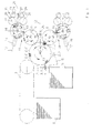
- the printing cylinder 1 is preceded by elements 4 for conveying a sheet to be printed from a stack of feed sheets 5 and transferring it to a pre-gripper system 6 which transfers the sheet to the printing cylinder 1.
- the sheets are fed to the printing cylinder 1 in such a way that only every second gripper row 3 of the printing cylinder is fed with a sheet.
- a sheet discharge designed as a delivery chain circle 7 is assigned to the printing cylinder 1, which takes over the printed sheet from the printing cylinder 1 and transports it to the delivery sheet stack 8.
- each cylinder group contains an offset cylinder 9 with i minus 1, which is in operative connection with the impression cylinder 1, ie two active surfaces and a printing form cylinder 10 with i minus 1, ie with two active surfaces, which is in active connection with the offset cylinder 9.
- the two cylinder groups 11; 18 are arranged in mirror image with respect to a horizontal ⁇ bisector 12 of an angle ⁇ , which is formed by the connecting lines of the two centers of the offset cylinders 9 with the center of the printing cylinder 13.
- One cylinder group 11 is thus arranged above and the other cylinder group 18 below the ⁇ bisector 12.
- the angle ⁇ is in the range of 60 °.
- the connecting line printing plate cylinder center 14 / offset cylinder center 15 is arranged at the cylinder group 11 arranged above the ⁇ bisector 12 at an angle ⁇ measured clockwise to the connecting line printing cylinder center 13 / offset cylinder center 15.
- the angle ⁇ is less than 180 ° and is preferably in the range of 145 °. Since the two cylinder groups 11; 18 are arranged in mirror image to the ⁇ - bisector 12, the angle ⁇ is measured in the cylinder group 18 arranged below the ⁇ - bisector in the counterclockwise direction with respect to the connecting line of the printing cylinder center 13 / offset cylinder center 15.
- An imaging device 16 is assigned to each printing form cylinder 10.
- the direction of extension 17 of the imaging device 16 which corresponds to the effective direction thereof, runs in the direction of the printing forme cylinder center 14 and is less than 90 °, preferably in the range of 80 °, for the cylinder group 11 located above the ⁇ bisector 12 at an angle ⁇ measured in the clockwise direction Connecting line printing plate cylinder center 14 / offset cylinder center 15 arranged.
- the angle ⁇ is measured in the counterclockwise direction with respect to the connecting line of the printing form cylinder center 14 / offset cylinder center 15.
- a coloring system 19 is assigned to each active surface of each printing form cylinder 10.
- the inking system contains an application roller 20.
- the application rollers 20 assigned to the printing form cylinder 10 are arranged in mirror image with respect to a horizontally arranged ⁇ bisector 21 of an angle ⁇ , which is formed by the connecting lines of the two application roller centers 22 with the printing form cylinder center 14.
- the angle ⁇ is in the range of 60 °.
- the inking system 19 is designed as an anilox inking unit.
- the anilox inking unit contains an ink metering roller 23, to which a doctor box 24 is assigned.
- the ink metering rollers 23, like the application rollers 20, are arranged in mirror image to the ⁇ bisector 21.
- the doctor boxes 24 assigned to the ink metering rollers 23 are arranged vertically one above the other.
- the cleaning device (FIG. 2) for the printing cylinder 1 and the two associated offset cylinders 9 is designed as a cylinder cleaning device 25 and is arranged on the ⁇ -bisector 12 in a stationary manner (second version) or displaceably on this (first version).
- the cylinder cleaning device 25 is designed as a cleaning device known per se according to the roller type. Cleaning devices of this type have at least one cleaning roller 26, which is driven either by force or by friction by contacting the cylinder or cylinders to be cleaned. If the cleaning roller 26 is forcibly driven, it is possible to drive it at a peripheral speed which is greater or less than the peripheral speed at which the cylinders to be cleaned rotate.
- the cleaning roller 26 can be designed in a known manner as a brush roller or can be provided with a fleece or elastic elevator.
- the cylinder cleaning device 25 shown in principle in FIG. 2 has a cleaning roller 26 which is forcibly driven by a motor 44.
- a moistening device 45 and a doctor blade 46 are in operative connection with the cleaning roller 26.
- the cylinder cleaning device 25 is designed as a functional unit and can be moved from a detent position 47 (full line representation in FIG. 2) along the ⁇ -bisector 12 to a first working position by means not shown 48 and a second working position 49 (dashed lines in Fig. 2) designed to be displaceable. In the second working position 49, the cleaning roller 26 is operatively connected to the printing cylinder 1.
- the first working position 48 is characterized in that the offset cylinder centers 15, when the offset cylinders are pivoted from the "pressure at" position 50 to the "pressure from” position 51, lie with the cleaning roller center 26.1 on a straight line g which is perpendicular to the ⁇ - Bisector 12 runs.
- the geometric dimensions are chosen so that in the first working position 48 the offset cylinders 9 and the cleaning roller 26 are operatively connected.
- the cylinder cleaning device 25 is moved along the ⁇ bisector 12 into the second working position 49 in the “pressure at” position 50, subsequently the offset cylinder 15 is placed next to the printing cylinder 1 so that the cylinder 1; 15 no longer touch and subsequently the printing cylinder 1 is cleaned by the cleaning roller 26 being provided with a cleaning medium by the moistening device 45. Finally, dirt on the printing cylinder is removed and removed by a doctor blade 46 placed on the cleaning roller 26. After the printing cylinder 1 has been cleaned, the cylinder cleaning device 25 is brought into the first working position 48, the offset cylinders 9 are pivoted into the “pressure from” position and the offset cylinders 9 are cleaned analogously to the printing cylinder 1.
- the cleaning device for the printing plate cylinder 10 and the two assigned application rollers 20 is designed as a roller cleaning device 27 and acts analogously to the cylinder cleaning device 25 shown in FIG. 2. For this reason, a separate illustration has been omitted and the corresponding reference numerals in FIG. 2 when used as a roller cleaning device 27 entered in brackets. It is also possible to use a roller cleaning device 27 to simultaneously clean the application rollers 20 and subsequently the printing plate cylinder 10 with the same roller cleaning device 27.
- the cylinder cleaning device 25 which is arranged stationary on the ⁇ -bisector 12, is designed as a cleaning device according to the belt type.
- Such cleaning devices usually have a cleaning belt 28 which is brought into or out of operative connection with the surfaces to be cleaned by pressing elements 29.
- the cleaning tape 28 is stored on a supply reel 52 and is guided through the pressing elements 29, removed from the supply reel 52 by means of a winding unit 53 and rewound if necessary.
- the cylinder cleaning device 25 is designed as a functional unit.
- the cleaning belt 28 can be provided with a cleaning agent for cleaning with the aid of devices not shown. It is also possible to provide the cleaning cloth pre-impregnated with a cleaning agent on the supply reel 52.
- the pressing elements 29 are optionally activated and thus the cleaning belt 28 is brought into contact with the cylinder surfaces to be cleaned and thus cleaned. It is thus possible to use a cylinder cleaning device 25 to immediately clean the offset cylinders 9 and the impression cylinder 1.
- the cleaning tape 28 is pulled from the supply spool 52 in a clocked manner so that always clean cleaning tape 28 comes into contact with the cylinder surfaces to be cleaned
- the cylinder cleaning device 25 according to the belt type is arranged in a stationary manner. It is also possible, in order to ensure good accessibility, to assign the cylinder cleaning device 25 according to the belt type to a parking position in addition to the working position shown in FIG. 3, which is provided at a distance from the offset cylinders 9.
- the cleaning device for the printing form cylinder 10 and the two assigned application rollers 20 is designed as a roller cleaning device 27 and acts analogously to that in FIG Fig. 3 shown cylinder cleaning device 25. For this reason, a separate representation omitted and in Fig. 3 the corresponding reference numerals when used entered as roller cleaning device 27 in brackets. So it is also possible with a roller cleaning device 27, the application rollers 20 and the To clean printing plate cylinder 10.
- the offset cylinders 9 are arranged in a known manner in eccentric bearings 30.
- the frame points 36 of the eccentric bearings 30 lie together with the offset cylinder centers 15 and the printing form cylinder centers 14 in a likewise known manner on a straight line.
- the printing form cylinders 10 are also arranged in eccentric bearings 37 in order to be able to implement tracking in the case of a paper thickness adjustment.
- a transmission means 40 attacks, which according to the embodiment.
- variable 1 (variant 1) consists of an output member 38 on which a coupling 39 engages, both coupling 39 engaging on a common articulation point 41 which lies on the ⁇ -bisector 12.
- the articulation point 41 is guided by a cylinder adjusting device 31, likewise arranged on the ⁇ bisector 12, on the ⁇ bisector 12 to the printing cylinder 1 or away from it.
- the cylinder actuating device 31 has a first actuating element 42 and a second actuating element 43.
- the first actuating element 42 is designed, for example, as a cylinder 32 which can be acted upon by a pressure medium and is operatively connected to the second actuating element 43, the second actuating element 43 being designed, for example, as an adjusting spindle 33 guided in a nut 34 fixed to the frame.
- Both the transmission means 41 and the cylinder setting device 31 are arranged mirror-symmetrically to the ⁇ -bisector 12. It is thus possible to simultaneously implement switching and actuating actions of the offset cylinders 9 with a cylinder actuating device 31.
- a "pressure on" or "pressure off” switching can be realized. According to the embodiment.
- the transmission means 40 acting on the eccentric bearings 30 are designed as output members 38, which are arranged in mirror image to the ⁇ bisector 12.
- the cylinder actuating device 31 is arranged on the ⁇ -bisector 12, the first actuating element 42 consisting of two cylinders 32 which are arranged in mirror image to the ⁇ -bisector 12 and can be acted upon by a pressure medium.
- Each cylinder 32 engages an output member and is supported against the second actuating element 43.
- the second actuator 43 consists of a nut 34 which is slidably mounted on an adjusting spindle 33 fixed to the frame.
- the mirror-image arrangement of the transmission means 40 acting on the eccentric bearing 30 and the cylinder actuating device 31 provided on the ⁇ bisector 12 makes it possible to implement switching and actuating actions on two offset cylinders 9 simultaneously or in succession with a cylinder actuating device 31.
- a paper thickness setting and, by means of the cylinders 32, a “pressure on” or “pressure off” position of the offset cylinders 9 can be implemented simultaneously or in succession.
Landscapes
- Engineering & Computer Science (AREA)
- Mechanical Engineering (AREA)
- Inking, Control Or Cleaning Of Printing Machines (AREA)
Claims (36)
- Machine d'impression offset feuille à feuille à plusieurs couleurs, comprenant une installation d'illustration et un cylindre de pression (1) avec (i) surfaces de pression (2) et des rangées de pinces (3), coopérant avec une alimentation de feuilles et une évacuation de feuilles à partir de chaque seconde rangée de pinces, du même côté de la machine et avec au moins deux groupes de cylindres (11, 18) comprenant chacun un cylindre porte-plaque (10) et un cylindre porte-blanchet (9) ayant chaque fois (i - 1) ≥ 2 surfaces actives,
chaque surface active du cylindre porte-plaque (10) étant associée à un système encreur (19) avec un cylindre applicateur (20) et à chaque cylindre porte plaque (10) est associée une installation d'illustration (16),
caractérisée en ce queles groupes de cylindres (11, 18) sont installés selon une symétrie plane par rapport à une bissectrice horizontale (12) d'un angle α formé par les lignes reliant le centre de chaque cylindre porte-blanchet (9) au centre du cylindre de pression (13),les cylindres applicateurs (22) étant installés de manière symétrique par rapport à un plan passant par la bissectrice (21) horizontale d'un angle γ compris entre les lignes passant par le centre (22) de chaque cylindre applicateur et le centre (14) du cylindre porte-plaque, etles directions des bissectrices des angles α et γ sont identiques et se trouvent sur le côté de la machine opposé à celui de l'alimentation et l'évacuation des feuilles. - Machine offset feuille à feuille à plusieurs couleurs selon la revendication 1,
caractérisée en ce que
l'angle α est de l'ordre de 60°. - Machine offset feuille à feuille à plusieurs couleurs selon la revendication 1,
caractérisée en ce que
la ligne de liaison reliant le centre (14) du cylindre porte-plaque et le centre (15) du cylindre porte-blanchet du groupe de cylindes (11) situé au dessus de la bissectrice (12) de l'angle α, fait un angle β mesuré dans le sens des aiguilles d'une montre qui est inférieur à 180°, cet angle étant pris par rapport à la ligne reliant le centre (13) du cylindre de pression et le centre (15) du cylindre porte-blanchet. - Machine offset feuille à feuille à plusieurs couleurs selon la revendication 3,
caractérisée en ce que
l'angle β est de l'ordre de 145°. - Machine offset feuille à feuille à plusieurs couleurs selon la revendication 1,
caractérisée en ce que
les installations d'illustration (16) associées au cylindre porte-plaque (10) sont symétriques selon un plan passant par la bissectrice (12) de l'angle α. - Machine offset feuille à feuille à plusieurs couleurs selon la revendication 1,
caractérisée en ce que
les systèmes d'encrage (19) associé à un cylindre porte plaque (10) sont équipés comme les dispositifs d'encrage Anilox dont les cylindres applicateurs (20) et les cylindres doseurs (23) sont symétriques par rapport à un plan passant par la bissectrice (21) d'un angle γ compris entre les lignes reliant le centre (22) de chaque cylindre applicateur et le centre (14) du cylindre porte plaque, la bissectrice (21) de l'angle γ s'étendant dans la direction horizontale et les boítes à racle (24) sont placées verticalement l'une au dessus de l'autre. - Machine offset feuille à feuille à plusieurs couleurs selon la revendication 6,
caractérisée en ce que
l'angle γ est de l'ordre de 60°. - Machine offset feuille à feuille à plusieurs couleurs selon la revendication 1,
caractérisée en ce qu'une installation de nettoyage de cylindres (25) est montée fixe sur la bissectrice (12) de l'angle α ou coulissante dans la direction de cette bissectrice (12) de l'angle α, pour le cylindre de pression (1) et les cylindres porte-blanchet (9),l'angle α ayant une valeur telle que les cylindres offset (9) soient écartés l'un de l'autre d'une distance permettant une coopération entre la surface des cylindres offset (9) et l'installation de nettoyage de cylindres (25). - Machine offset feuille à feuille à plusieurs couleurs selon la revendication 1,
caractérisée en ce queles cylindres porte-blanchet (9) sont montés chaque fois dans un palier excentrique (30) pour la position de mise en pression et la position dégagée ainsi que pour le réglage de l'épaisseur du papier, et un moyen de transmission (40) agit sur chaque palier excentrique (30),les moyens de transmission (40) étant prévus de manière symétrique par rapport à un plan passant par la bissectrice (12) de l'angle α et coopérant avec une installation commune (31) de réglage des cylindres. - Machine offset feuille à feuille à plusieurs couleurs selon la revendication 9,
caractérisée en ce que
l'installation de réglage des cylindres (31) est montée coulissante dans la direction de la bissectrice (12) de l'angle α. - Machine offset feuille à feuille à plusieurs couleurs selon la revendication 9,
caractérisée en ce que
l'installation de réglage des cylindres (31) se compose d'un premier élément de réglage (42) et d'un second élément de réglage (43). - Machine offset feuille à feuille à plusieurs couleurs selon les revendications 9 et 11,
caractérisée en ce que
le premier élément de réglage (42) réalise une position de mise en pression et une position de dégagement et le second élément de réglage (43) règle les cylindres porte-blanchet (9) en fonction de l'épaisseur du papier. - Machine offset feuille à feuille à plusieurs couleurs selon la revendication 12,
caractérisée en ce que
le premier élément de réglage (42) comporte au moins un cylindre (32) susceptible de recevoir un fluide sous pression. - Machine offset feuille à feuille à plusieurs couleurs selon la revendication 12,
caractérisée en ce que
la seconde installation de réglage (43) se compose des éléments d'articulation vis (33) / écrou (34). - Machine offset feuille à feuille à plusieurs couleurs selon les revendications 9 et 12,
caractérisée en ce que
les cylindres (9) peuvent être rapprochés en position (39) de mise en pression. - Machine offset feuille à feuille à plusieurs couleurs selon la revendication 8,
caractérisée en ce que
l'installation de nettoyage de cylindre (25) installée de manière fixe sur la bissectrice (12) de l'angle α est un ruban de nettoyage (28). - Machine offset feuille à feuille à plusieurs couleurs selon les revendications 8 et 16,
caractéirisée en ce que
l'installation de nettoyage des cylindres (25) comporte trois éléments de pression (29) qui applique la toile de nettoyage (28) contre la surface des cylindres porte-blanchet (9) et celle du cylindre de pression (1) pour coopérer avec ces surfaces. - Machine offset feuille à feuille à plusieurs couleurs selon la revendication 17,
caractérisée en ce que
les éléments de pression (29) peuvent être activés sélectivement. - Machine offset feuille à feuille à plusieurs couleurs selon la revendication 8,
caractérisée en ce que
la direction de l'installation de nettoyage de cylindre (25) coulissante suivant la bissectrice (21) de l'angle α comprend au moins un cylindre de nettoyage (26). - Machine offset feuille à feuille à plusieurs couleurs selon les revendications 8 et 19,
caractérisée en ce que
l'installation de nettoyage de cylindres (25) peut être conduite d'une position de repos (47) au choix, dans une première position active (48) ou dans une seconde position active (49). - Machine offset feuille à feuille à plusieurs couleurs selon les revendications 8 et 20,
caractérisée en ce que
dans leur première position de travail (28) les centres (15) des cylindres porte-blanchet se trouvent dans une position dégagée (51) pour les cylindres porte-blanchet (9) et le centre (26.1) du cylindre de nettoyage (26) se trouve sur une droite g. - Machine offset feuille à feuille à plusieurs couleurs selon la revendication 21,
caractérisée en ce que
la droite g est perpendiculaire à la bissectrice (12) de l'angle α. - Machine offset feuille à feuille à plusieurs couleurs selon la revendication 21,
caractérisée en ce que
les centres (15) des cylindres porte-blanchet en position dégagée (51) sont écartés l'un de l'autre pour que leur surface coopère avec la surface du cylindre de nettoyage (26). - Machine offset feuille à feuille à plusieurs couleurs selon les revendications 8 et 20,
caractérisée en ce que
dans la seconde position active (49), le cylindre de nettoyage (26) coopère avec le cylindre de pression (1). - Machine offset feuille à feuille à plusieurs couleurs selon la revendication 1,
caractérisée en ce qu'une installation de nettoyage de cylindres (27) pour le cylindre porte plaque (10) et le cylindre applicateur (20) est prévu de manière fixe sur la bissectrice (21) de l'angle γ ou de façon coulissante dans la direction de cette bissectrice (21) de l'angle γ,l'angle γ ayant une valeur telle que les cylindres applicateurs (21) sont distants l'un de l'autre d'une distance permettant la coopération entre la surface des cylindres applicateurs (20) et de l'installation de nettoyage de cylindres (27). - Machine offset feuille à feuille à plusieurs couleurs selon les revendications 8 et 25,
caractérisée en ce que
l'installation de nettoyage de cylindres (27) installée de manière fixe sur la bissectrice (21) de l'angle γ comporte une bande de nettoyage (28). - Machine offset feuille à feuille à plusieurs couleurs selon les revendications 8, 25, 26,
caractérisée en ce que
l'installation de nettoyage de cylindre (27) comporte trois éléments de pression (29) qui font coopérer la bande de nettoyage (28) avec la surface des cylindres applicateurs (20). - Machine offset feuille à feuille à plusieurs couleurs selon la revendication 27,
caractérisée en ce que
les éléments de pression (29) peuvent être activés sélectivement. - Machine offset feuille à feuille à plusieurs couleurs selon les revendications 8 et 25,
caractérisée en ce que
l'installation de nettoyage (27) coulissante dans la direction de la bissectrice (21) de l'ange γ comporte au moins un cylindre de nettoyage (26). - Machine offset feuille à feuille à plusieurs couleurs selon les revendications 8, 25, 29,
caractérisée en ce que
l'installation de nettoyage de cylindres (27) peut être conduite à partir d'une position de repos (47), au choix dans une première position active (48) ou dans une seconde position active (49). - Machine offset feuille à feuille à plusieurs couleurs selon les revendications 8, 25, 30,
caractérisée en ce que
dans la première position active (48), le centre (22) des cylindres applicateurs se trouve dans la position dégagée (51) des cylindres applicateurs (28) et le centre (26.1) des cylindres de nettoyage (26) se trouve sur une droite (g1). - Machine offset feuille à feuille à plusieurs couleurs selon la revendication 31,
caractérisée en ce que
la droite (g1) est parallèle à la bissectrice (21) de l'angle γ. - Machine offset feuille à feuille à plusieurs couleurs selon la revendication 31,
caractérisée en ce que
les centres (22) des cylindres applicateurs sont écartés pour la position dégagée (51) d'une distance telle que leur surface (20) coopère avec la surface du cylindre de nettoyage (26). - Machine offset feuille à feuille à plusieurs couleurs selon les revendications 25 et 30,
caractérisé en ce que
dans la seconde position active (49), le cylindre de nettoyage (26) coopère avec le cylindre porte-plaque (10). - Machine offset feuille à feuille à plusieurs couleurs selon la revendication 5,
caractérisée en ce que
la direction (17) de l'installation d'illustration (16), dirigée vers le centre (14) du cylindre porte-plaque, de l'installation d'illustration (16) au dessus de la bissectrice (12) de l'angle α, fait un angle δ, mesuré dans la direction des aiguilles d'une montre, qui est inférieur à 90° par rapport à la ligne reliant le centre (14) du cylindre porte-plaque au centre (15) du cylindre porte-blanchet. - Machine offset feuille à feuille à plusieurs couleurs selon la revendication 35,
caractérisée en ce que
l'angle δ est de l'ordre de 90°.
Applications Claiming Priority (7)
| Application Number | Priority Date | Filing Date | Title |
|---|---|---|---|
| DE19715243 | 1997-04-12 | ||
| DE1997115242 DE19715242A1 (de) | 1997-04-12 | 1997-04-12 | Druckmaschine mit mindestens zwei einem Druckzylinder zugeordneten Offsetzylindern |
| DE1997115243 DE19715243B4 (de) | 1997-04-12 | 1997-04-12 | Druckmaschine mit Reinigungseinrichtungen zum Reinigen von Zylindern und Walzen |
| DE19715242 | 1997-04-12 | ||
| DE19715241 | 1997-04-12 | ||
| DE1997115241 DE19715241A1 (de) | 1997-04-12 | 1997-04-12 | Druckmaschine |
| PCT/DE1998/001044 WO1998046427A1 (fr) | 1997-04-12 | 1998-04-09 | Machine d'impression offset multicolore a feuilles avec dispositif de formation d'image, un dispositif de nettoyage et reglage de l'epaisseur du papier |
Publications (2)
| Publication Number | Publication Date |
|---|---|
| EP0977667A1 EP0977667A1 (fr) | 2000-02-09 |
| EP0977667B1 true EP0977667B1 (fr) | 2002-03-27 |
Family
ID=27217291
Family Applications (1)
| Application Number | Title | Priority Date | Filing Date |
|---|---|---|---|
| EP98931908A Expired - Lifetime EP0977667B1 (fr) | 1997-04-12 | 1998-04-09 | Machine d'impression offset multicolore a feuilles avec dispositif de formation d'image, un dispositif de nettoyage et reglage de l'epaisseur du papier |
Country Status (3)
| Country | Link |
|---|---|
| EP (1) | EP0977667B1 (fr) |
| DE (1) | DE59803516D1 (fr) |
| WO (1) | WO1998046427A1 (fr) |
Cited By (1)
| Publication number | Priority date | Publication date | Assignee | Title |
|---|---|---|---|---|
| WO2019055015A1 (fr) * | 2017-09-14 | 2019-03-21 | Hp Indigo B.V. | Éléments de nettoyage pour appareil d'impression |
Family Cites Families (9)
| Publication number | Priority date | Publication date | Assignee | Title |
|---|---|---|---|---|
| DE432853C (de) * | 1926-08-17 | Albert & Cie A G | Rotationsgummidruckmaschine | |
| DE402059C (de) * | 1922-03-30 | 1924-09-12 | Vogtlaendische Maschinenfabrik | Rotationsgummidruckmaschine fuer mehrfarbigen Bogendruck |
| DE1235953B (de) * | 1965-03-17 | 1967-03-09 | Koenig & Bauer Schnellpressfab | Bogen-Offset-Rotationsdruckmaschine fuer wahlweisen Schoen- und Widerdruck oder Schoendruck |
| DE2409219A1 (de) * | 1974-02-27 | 1975-09-04 | Maschf Augsburg Nuernberg Ag | Satelliten-rotations-offsetdruckwerk |
| DE3233021A1 (de) * | 1982-09-06 | 1984-03-08 | Rotaprint Gmbh, 1000 Berlin | Offset-drucker als vervielfaeltiger |
| JPS6064849A (ja) * | 1983-09-19 | 1985-04-13 | Katsuji Akiyama | 両面4色刷りオフセット印刷機 |
| ATE84257T1 (de) * | 1988-03-23 | 1993-01-15 | Roland Man Druckmasch | Vorrichtung zum reinigen der arbeitsflaechen einer arbeitsmaschine, insbesondere in einer druckmaschine. |
| DE19523378A1 (de) * | 1995-06-30 | 1997-01-02 | Koenig & Bauer Albert Ag | Bogenoffsetrotationsdruckmaschine |
| DE29617170U1 (de) * | 1996-10-02 | 1996-11-21 | MAN Roland Druckmaschinen AG, 63075 Offenbach | Vorrichtung zum Waschen von Zylindern einer Druckmaschine |
-
1998
- 1998-04-09 WO PCT/DE1998/001044 patent/WO1998046427A1/fr not_active Ceased
- 1998-04-09 EP EP98931908A patent/EP0977667B1/fr not_active Expired - Lifetime
- 1998-04-09 DE DE59803516T patent/DE59803516D1/de not_active Expired - Fee Related
Cited By (4)
| Publication number | Priority date | Publication date | Assignee | Title |
|---|---|---|---|---|
| WO2019055015A1 (fr) * | 2017-09-14 | 2019-03-21 | Hp Indigo B.V. | Éléments de nettoyage pour appareil d'impression |
| CN111051065A (zh) * | 2017-09-14 | 2020-04-21 | 惠普印迪格公司 | 用于打印设备的清洁元件 |
| CN111051065B (zh) * | 2017-09-14 | 2021-10-01 | 惠普印迪格公司 | 打印设备部件清洁方法、清洁设备和打印设备 |
| US11433663B2 (en) | 2017-09-14 | 2022-09-06 | Hp Indigo B.V. | Cleaning elements for print apparatus |
Also Published As
| Publication number | Publication date |
|---|---|
| WO1998046427A1 (fr) | 1998-10-22 |
| EP0977667A1 (fr) | 2000-02-09 |
| DE59803516D1 (de) | 2002-05-02 |
Similar Documents
| Publication | Publication Date | Title |
|---|---|---|
| EP0078444B1 (fr) | Dispositif d'encrage pour machines à imprimer offset | |
| DE4303797C2 (de) | Rotationsdruckmaschine zum Bedrucken von Bogen | |
| DE3109964A1 (de) | "sammeldruck-rotationsmaschinendruckwerk fuer wertpapierdruck" | |
| DE2531886A1 (de) | Reinigungsvorrichtung fuer druckwerkszylinder in offsetdruckmaschinen | |
| CH655054A5 (de) | Sammeldruck-rotationsmaschinendruckwerk fuer wertpapierdruck. | |
| EP0384385A2 (fr) | Dispositif pour changer la position d'une bande destinée à être imprimée | |
| DE102006002304A1 (de) | Bogendruckmaschine | |
| DE102009002103B4 (de) | Druckmaschine und ein Verfahren zum Bedrucken eines bahnförmigen Bedruckstoffs | |
| WO2010086263A1 (fr) | Presse à feuilles | |
| EP0977667B1 (fr) | Machine d'impression offset multicolore a feuilles avec dispositif de formation d'image, un dispositif de nettoyage et reglage de l'epaisseur du papier | |
| DE19715243B4 (de) | Druckmaschine mit Reinigungseinrichtungen zum Reinigen von Zylindern und Walzen | |
| EP0085752A1 (fr) | Groupe imprimant pour rotative offset | |
| EP1498264B1 (fr) | Imprimante | |
| DE8224875U1 (de) | Farbwerk für Offsetdruckmaschinen | |
| EP0870608B1 (fr) | Presse flexographique à feuilles | |
| DE4233261C2 (de) | Vorrichtung zur Bahnführung, mit Perforiermöglichkeit in einer Rollenrotationsdruckmaschine | |
| EP1109671A2 (fr) | Procede et dispositif permettant de produire un imprime polychrome | |
| EP1106350B1 (fr) | Dispositif pour imprimer de feuilles recto-verso dans de machines d'impression offset à feuille | |
| DE3523331C2 (fr) | ||
| DE102005018821A1 (de) | Druckwerk einer Druckmaschine | |
| DE3109977A1 (de) | "sammeldruck-rotationsmaschinendruckwerk fuer wertpapierdruck" | |
| DE3443765A1 (de) | An- und abstellvorrichtung fuer farbwalzen in druckmaschinen | |
| DE102022106368A1 (de) | Heberfarbwerk und Verfahren zum Betreiben eines Heberfarbwerkes | |
| DE102004047168A1 (de) | Druckeinheit einer Druckmaschine | |
| DE3901177C2 (de) | Mehrfarbendruckmaschine |
Legal Events
| Date | Code | Title | Description |
|---|---|---|---|
| PUAI | Public reference made under article 153(3) epc to a published international application that has entered the european phase |
Free format text: ORIGINAL CODE: 0009012 |
|
| 17P | Request for examination filed |
Effective date: 19991108 |
|
| AK | Designated contracting states |
Kind code of ref document: A1 Designated state(s): DE FR GB |
|
| 17Q | First examination report despatched |
Effective date: 20000821 |
|
| GRAG | Despatch of communication of intention to grant |
Free format text: ORIGINAL CODE: EPIDOS AGRA |
|
| GRAG | Despatch of communication of intention to grant |
Free format text: ORIGINAL CODE: EPIDOS AGRA |
|
| GRAH | Despatch of communication of intention to grant a patent |
Free format text: ORIGINAL CODE: EPIDOS IGRA |
|
| GRAH | Despatch of communication of intention to grant a patent |
Free format text: ORIGINAL CODE: EPIDOS IGRA |
|
| REG | Reference to a national code |
Ref country code: GB Ref legal event code: IF02 |
|
| GRAA | (expected) grant |
Free format text: ORIGINAL CODE: 0009210 |
|
| RIN1 | Information on inventor provided before grant (corrected) |
Inventor name: KESSLER, VOLKER Inventor name: BECKER, UWE Inventor name: PSCHEIDL, MICHAEL Inventor name: NERGER, REINHARD Inventor name: JENTZSCH, ARNDT |
|
| AK | Designated contracting states |
Kind code of ref document: B1 Designated state(s): DE FR GB |
|
| REF | Corresponds to: |
Ref document number: 59803516 Country of ref document: DE Date of ref document: 20020502 |
|
| GBT | Gb: translation of ep patent filed (gb section 77(6)(a)/1977) |
Effective date: 20020613 |
|
| ET | Fr: translation filed | ||
| PLBE | No opposition filed within time limit |
Free format text: ORIGINAL CODE: 0009261 |
|
| STAA | Information on the status of an ep patent application or granted ep patent |
Free format text: STATUS: NO OPPOSITION FILED WITHIN TIME LIMIT |
|
| 26N | No opposition filed |
Effective date: 20021230 |
|
| PGFP | Annual fee paid to national office [announced via postgrant information from national office to epo] |
Ref country code: DE Payment date: 20080424 Year of fee payment: 11 |
|
| PGFP | Annual fee paid to national office [announced via postgrant information from national office to epo] |
Ref country code: FR Payment date: 20080412 Year of fee payment: 11 |
|
| PGFP | Annual fee paid to national office [announced via postgrant information from national office to epo] |
Ref country code: GB Payment date: 20080421 Year of fee payment: 11 |
|
| GBPC | Gb: european patent ceased through non-payment of renewal fee |
Effective date: 20090409 |
|
| REG | Reference to a national code |
Ref country code: FR Ref legal event code: ST Effective date: 20091231 |
|
| PG25 | Lapsed in a contracting state [announced via postgrant information from national office to epo] |
Ref country code: DE Free format text: LAPSE BECAUSE OF NON-PAYMENT OF DUE FEES Effective date: 20091103 |
|
| PG25 | Lapsed in a contracting state [announced via postgrant information from national office to epo] |
Ref country code: GB Free format text: LAPSE BECAUSE OF NON-PAYMENT OF DUE FEES Effective date: 20090409 Ref country code: FR Free format text: LAPSE BECAUSE OF NON-PAYMENT OF DUE FEES Effective date: 20091222 |