EP0977932B1 - Verfahren und vorrichtung zur benutzung in produktionstests einer erwarteten permeablen formation - Google Patents
Verfahren und vorrichtung zur benutzung in produktionstests einer erwarteten permeablen formation Download PDFInfo
- Publication number
- EP0977932B1 EP0977932B1 EP98914162A EP98914162A EP0977932B1 EP 0977932 B1 EP0977932 B1 EP 0977932B1 EP 98914162 A EP98914162 A EP 98914162A EP 98914162 A EP98914162 A EP 98914162A EP 0977932 B1 EP0977932 B1 EP 0977932B1
- Authority
- EP
- European Patent Office
- Prior art keywords
- formation
- fluid
- channel
- well
- permeable
- Prior art date
- Legal status (The legal status is an assumption and is not a legal conclusion. Google has not performed a legal analysis and makes no representation as to the accuracy of the status listed.)
- Expired - Lifetime
Links
- 230000015572 biosynthetic process Effects 0.000 title claims abstract description 79
- 238000004519 manufacturing process Methods 0.000 title claims abstract description 47
- 238000012360 testing method Methods 0.000 title claims abstract description 34
- 238000000034 method Methods 0.000 title claims description 12
- 238000005755 formation reaction Methods 0.000 claims abstract description 78
- 239000012530 fluid Substances 0.000 claims abstract description 73
- 238000007789 sealing Methods 0.000 claims abstract description 7
- 238000009530 blood pressure measurement Methods 0.000 claims abstract 2
- 238000004891 communication Methods 0.000 claims description 5
- 239000007788 liquid Substances 0.000 claims description 4
- 230000002441 reversible effect Effects 0.000 claims description 2
- 238000006073 displacement reaction Methods 0.000 claims 2
- 238000004880 explosion Methods 0.000 abstract description 2
- 238000012546 transfer Methods 0.000 abstract description 2
- 238000005553 drilling Methods 0.000 description 6
- 230000000638 stimulation Effects 0.000 description 4
- 238000010420 art technique Methods 0.000 description 3
- 239000004568 cement Substances 0.000 description 3
- 230000000694 effects Effects 0.000 description 3
- 239000004576 sand Substances 0.000 description 3
- 238000004458 analytical method Methods 0.000 description 2
- 230000007613 environmental effect Effects 0.000 description 2
- 239000007789 gas Substances 0.000 description 2
- 229930195733 hydrocarbon Natural products 0.000 description 2
- 150000002430 hydrocarbons Chemical class 0.000 description 2
- 238000002360 preparation method Methods 0.000 description 2
- 230000008569 process Effects 0.000 description 2
- 239000000126 substance Substances 0.000 description 2
- XLYOFNOQVPJJNP-UHFFFAOYSA-N water Substances O XLYOFNOQVPJJNP-UHFFFAOYSA-N 0.000 description 2
- 230000008901 benefit Effects 0.000 description 1
- 238000002485 combustion reaction Methods 0.000 description 1
- 238000001816 cooling Methods 0.000 description 1
- 230000007423 decrease Effects 0.000 description 1
- 230000007812 deficiency Effects 0.000 description 1
- 230000002950 deficient Effects 0.000 description 1
- 238000011161 development Methods 0.000 description 1
- 238000002347 injection Methods 0.000 description 1
- 239000007924 injection Substances 0.000 description 1
- 238000012423 maintenance Methods 0.000 description 1
- 238000005259 measurement Methods 0.000 description 1
- 238000012986 modification Methods 0.000 description 1
- 230000004048 modification Effects 0.000 description 1
- 238000005086 pumping Methods 0.000 description 1
- 230000009467 reduction Effects 0.000 description 1
- 230000008439 repair process Effects 0.000 description 1
- 239000011435 rock Substances 0.000 description 1
- 239000000243 solution Substances 0.000 description 1
- 230000004936 stimulating effect Effects 0.000 description 1
- 230000001988 toxicity Effects 0.000 description 1
- 231100000419 toxicity Toxicity 0.000 description 1
- 239000003643 water by type Substances 0.000 description 1
Images


Classifications
-
- E—FIXED CONSTRUCTIONS
- E21—EARTH OR ROCK DRILLING; MINING
- E21B—EARTH OR ROCK DRILLING; OBTAINING OIL, GAS, WATER, SOLUBLE OR MELTABLE MATERIALS OR A SLURRY OF MINERALS FROM WELLS
- E21B49/00—Testing the nature of borehole walls; Formation testing; Methods or apparatus for obtaining samples of soil or well fluids, specially adapted to earth drilling or wells
- E21B49/008—Testing the nature of borehole walls; Formation testing; Methods or apparatus for obtaining samples of soil or well fluids, specially adapted to earth drilling or wells by injection test; by analysing pressure variations in an injection or production test, e.g. for estimating the skin factor
Definitions
- This invention relates to a method and an apparatus for use in production test of a formation expected to be permeable. After having pointed out the existence of hydrocarbons upon drilling for oil and gas, a so-called production test is carried out, in order to provide information about permeable layers outside the bore hole or well itself.
- the well Prior to a production test, when reservoir fluid is allowed to flow out of the formation, the well is provided with some equipment, including means to control the flow rate and measuring equipment to measure pressure and flow rate.
- a production test has two phases, each with a duration of e.g. 24 hours. In both phases, a constant fluid flow is established from the formation.
- Sealing means e.g. in the form of annulus packers, are also adapted to take care of security requirements.
- the present invention is directed to a method and an apparatus for maintaining a constant flow of reservoir fluid in the well while pressure and, possibly, other parameters are read off.
- tubing By a production test it is known to conduct fluid from the reservoir to the surface through a so-called tubing, which is installed in the well. Sealing means are disposed within the annulus between the production tubing and the well wall, preferably on a place where a well casing has been installed, so that reservoir fluid is conducted to the surface through the tubing and not through the annulus.
- the tubing is assigned a valve adapted to control the fluid flow, and sensors and measuring equipment are disposed, at least for allowing the reading off and recording time, flow rate in the tubing and pressure within the well.
- Reservoir fluid constitutes, when it reaches the surface, a safety risk due to danger of explosion, fire hazard and toxicity. Therefore, substantial security measures must be made in connection with a production test. Additionally, reservoir fluid constitutes an environmental problem because production tests naturally are carried out before one takes the costs of installing process equipment. Therefore, it has been customary to conduct reservoir fluid to a burner. Due to the fact that combustion causes unwanted escapes of environmental gases and uncontrolled amounts of hydrocarbons into the sea, there exist some places, such as on the Norwegian continental shelf, where, owing to restrictions on burning and limitation in periods during a year for testing, it has become interesting to collect produced reservoir fluid and convey it to a suitable process plant. Even if this is an environmentally satisfactory solution, it is, nevertheless, awkward, price-raising as well as exhibitting many restrictions both in time and with respect to weather conditions.
- the preparations taking place before production testing comprise typically setting and cementing of casings for insulating various permeable layers, and to take care of safety requirements. Additionally, special production tubing is used down to the layer/bed to be tested. These preparations are time-consuming and expensive. Safety considerations make it some times necessary to strengthen an already set well casing, perhaps over the entire or a substantial part of the length of the well; particularly in high pressure wells it might be required to install extra casings in the upper parts of the well.
- Today's system can take care of drilling of wells in deep waters, but does not provide a safe and secure production testing. In deep water, it is difficult to take care of security in case the drilling vessel drifts out of position, or whenever the riser is subjected to large, uncontrollable and not measurable vibrations or leeway. Such a situation requires a rapid disconnection of the riser or production tubing subsequently to the closing of the production valve at the seabed. To-day's system is defective in respect of reacting on and point out dangerous situations.
- Such stimulation may consist in the addition of chemicals into the formation in order to increase the flow rate.
- a simple well stimulation consists in subjecting the formation to pressure pulses so that it cracks and, thus, becomes more permeable, so-called ''fracturing'' of the formation.
- a side-effect of fracturing can be a large increase in the amount of sand accompanying the reservoir fluid.
- it may in some relations be of interest to be able to effect a well stimulation in order to observe the effect thereof. Again, the case is such that an ordinary production equipment is adapted to avoid, withstand, resist and separate out sand, while corresponding measures are of less importance when carrying out a production test.
- the object of the invention is to provide a method and an apparatus for production testing a well where the described disadvantages of prior art technique have been avoided.
- a main feature of the invention consists in that fluid is conducted from a first, expected permeable formation to a second permeable formation as opposed to prior art technique where fluid is conducted between a formation and the surface.
- at least one channel connection is established between two formations, of which one (a first) formation is the one to be production tested.
- sealing means are disposed to limit the fluid flow to take place only between the formations through the channel connection(s).
- the sealing means e.g. annulus packers, prevent fluid from flowing between the formations, outside the channel(s)
- flow controlling means are disposed, inclusive a valve and, possibly, a pump, operable from the surface in order to control the fluid flow in the channel and, thus, between the formations.
- a sensor for flow rate in the channel is disposed. This sensor may, possibly, be readable from an surface position.
- sensors adapted to read pressure, temperature, detect sand, water and the like from the surface may be disposed.
- sensors of each type may be disposed in order to monitor desired parameters at several places within the channel.
- sensors for pressure and temperature are disposed within the well and, moreover, known equipment for timekeeping and recording of measuring values are used.
- a production test by means of the flow rate sensor, the adjustable valve and, possibly, by means of said pump, a constant fluid flow is established and maintained in the channel, fluid flowing from one formation to the other formation. Pressure and, possibly, other well parameters are read and recorded as previously known. Thereafter, the fluid flow is closed, and a pressure built up within the well is monitored and recorded as known.
- a production test might be extended to comprise a reversed flow through the utilisation of a reversible pump, so that fluid can be pumped in the opposite direction between the two formations.
- Storing produced reservoir fluid in a formation results in the advantage that the fluid may have approximately reservoir conditions when it is conducted back into the reservoir.
- well stimulating measures in the formation being production tested may be used. Fracturing may be achieved as known per se.
- the well is supplied with pressurised liquid, e.g. through a drill string coupled to the channel.
- a production test is carried out, such as explained.
- a reversed production test may alternately give both injection and production date from two separated layers without having to pull the test string.
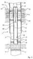
- reference numeral 1 denotes a part of a vertical well lined with a casing 2.
- the well 1 is extended with an open (not lined) hole 3 drilled through a first, expected permeable formation 4 to be production tested.
- the casing 2 is provided with a perforation 5 in an area where the well 1 passes through a second, permeable formation 6.
- second permeable formation 6 is not insulated by means of casings (2 in figure 1).
- First formation 4 is insulated from possible permeable formations adjacent the bottom of the well by means of a bottom packer 7.
- a tubular channel 8 extends concentrically with the well 1 from the area at first formation 4 to a place above the perforations 5.
- annulus 9 is formed between the channel 8 and the wall defining the open hole 3 and between the channel 8 and the casing 2.
- the channel 8 is closed at the upper end and, according to figures 1 and 2, open at the lower end.
- the channel 8 is provided with gates 13 establishing a fluid communication between the channel 8 and the annulus 9 outside the channel.
- fluid may flow from the first formation 4 to the well 1 and into the channel 8 at the lower end thereof, through the channel 8 and out through the gates 13 and further, through the perforations 5, to second formation 6.
- the annulus packer 7 When the annulus packer 7 is mounted to the channel-forming pipe 8, the latter may be closed at the lower end thereof which, according to figure 1a, is positioned below the first, expected permeable formation layer 4.
- the channel-forming pipe 8 In an area above the annulus packer 7, the channel-forming pipe 8 is, thus, provided with through-going lateral gates 21 which, together with the through-going lateral gates 13, establish fluid communication between the formations 4, 6.
- a remotely operable valve (not shown) is disposed, said valve being adapted to control a fluid flow through the channel 8.
- the valve may, as known per se, comprise a remotely operated displaceable, perforated sleeve 14 adapted to cover the gates 13, wholly or in part, the radially directed holes 14' of the sleeve 14 being brought to register more or less with the gates 13 or not to register therewith.
- remotely readable sensors are disposed, inclusive a pressure sensor 15 and a flow sensor 16 and a temperature sensor 17.
- the channel 8 may be assigned a pump 18 adapted to drive a flow of fluid through the channel 8.
- the pump can be driven by a motor 19 placed in the extension of the channel 8.
- a drive shaft 20 between motor 19 and pump 18 is passed pressure-tight through the upper closed end of the channel 8.
- the motor 19 may be of a hydraulic type, adapted to be driven by a liquid, e.g. a drilling fluid which, as known, is supplied through a drill string or a coilable tubing, not shown.
- a liquid e.g. a drilling fluid which, as known, is supplied through a drill string or a coilable tubing, not shown.
- an electrical motor can be used which can be cooled through the circulation of drilling liquid or through conducting fluid flowing in the channel 8, through a cooling jacket of the motor 19.
- sensors may be disposed, in order to sense and point out communication or cross flowing to or from the permeable layers, above or below the annulus.
Landscapes
- Mining & Mineral Resources (AREA)
- Engineering & Computer Science (AREA)
- Geology (AREA)
- Life Sciences & Earth Sciences (AREA)
- Geochemistry & Mineralogy (AREA)
- Fluid Mechanics (AREA)
- Physics & Mathematics (AREA)
- Analytical Chemistry (AREA)
- Chemical & Material Sciences (AREA)
- General Life Sciences & Earth Sciences (AREA)
- Environmental & Geological Engineering (AREA)
- Investigation Of Foundation Soil And Reinforcement Of Foundation Soil By Compacting Or Drainage (AREA)
- Separation Using Semi-Permeable Membranes (AREA)
- Examining Or Testing Airtightness (AREA)
- Measuring Fluid Pressure (AREA)
- Earth Drilling (AREA)
- Geophysics And Detection Of Objects (AREA)
- Consolidation Of Soil By Introduction Of Solidifying Substances Into Soil (AREA)
Claims (10)
- Verfahren zur Verwendung in Verbindung mit einer erwarteten permeablen ersten Formation (4), bei dem ein daraus strömendes Fluid während eines Produktionstests u.a. einer Druckmessung und einer Strömungsmengensteuerung unterworfen wird, dadurch gekennzeichnet, dass wenigstens ein definierter Fluidströmungsweg (8) zwischen der erwarteten permeablen ersten Formation (4) und einer permeablen zweiten Formation (6) geschaffen wird, und dass aus der ersten Formation (4) ausströmendes Fluid über den Fluidströmungsweg (8) zu der zweiten Formation (6) geführt wird, die dieses Fluid aufnimmt und es wenigstens zeitweise hält.
- Verfahren nach Anspruch 1, dadurch gekennzeichnet, dass der Fluidströmungsweg (die Fluidströmungswege) mittels eines kanalbildenden Rohrs (kanalbildender Rohre) (8) geschaffen wird (werden), das vorzugsweise konzentrisch zu der umgebenden Bohrlochwand/Casingfläche zwischen der ersten und zweiten Formation (4, 6) angeordnet wird, die auf unterschiedlichen Höhen liegen, und dass Dichtungseinrichtungen (7, 10, 12, 11) angeordnet werden, um zu verhindern, dass Fluid aus der ersten Formation (4) zu der zweiten Formation (6) außerhalb des Fluidströmungswegs (der Fluidströmungswege) (8) strömt.
- Verfahren nach Anspruch 1 oder 2, dadurch gekennzeichnet, dass nach einer Übertragung des Fluids von der ersten Formation (4) zu der zweiten Formation (6) ein umgekehrter Produktionstest dadurch durchgeführt wird, dass (übertragenes) Fluid unter Zwang aus der zweiten Formation (6) zu der ersten Formation (4) zurückgebracht wird.
- Verfahren nach einem der vorhergehenden Ansprüche, dadurch gekennzeichnet, dass ein Aufbrechen der ersten Formation (4) durchgeführt wird, wobei dem Bohrloch in dem Bereich der ersten Formation (4) unter Druck gesetzte Flüssigkeit beispielsweise durch einen Bohrstrang zugeführt wird, der mit dem Fluidströmungsweg (8) verbunden ist.
- Vorrichtung zur Durchführung des Verfahrens nach Anspruch 1, die in einem Bohrloch (1) zwischen zwei Formationen, einer erwarteten permeablen ersten Formation (4), an der ein Produktionstest durchgeführt werden soll, und einer zweiten Formation (6) angebracht werden soll, wobei sie für den Produktionstest einen oder mehrere Sensoren/Messeinrichtungen/Regeleinrichtungen/Steuereinrichtungen (15, 17) für u.a. ein Erfassen/Messen, Aufzeichnen von Druckbedingungen und einer Strömungsmenge sowie zur Einstellung der letztgenannten umfasst, dadurch gekennzeichnet, dass die Vorrichtung wenigstens ein kanalbildendes Rohr (8) umfasst, das innerhalb des Bohrlochs (1) einen Fluidströmungsweg zwischen einer ersten Formation (4), an der ein Produktionstest durchgeführt werden soll, und einer zweiten permeablen Formation (6) schafft, wobei der Vorrichtung zugeordnete Dichtungseinrichtungen (7, 10, 11, 12) angeordnet werden, um die Fluidströmung zwischen den Formationen (4, 6) so zu beschränken, dass sie nur in dem gebildeten Kanal oder den Kanälen (8) stattfindet, um wenigstens einen beschränkten Fluidströmungsweg zu schaffen, so dass dieser Kanal bzw. diese Kanäle (8) die einzige Fluidverbindung zwischen den zwei permeablen Formationen (4, 6) bilden.
- Vorrichtung nach Anspruch 5, dadurch gekennzeichnet, dass das kanalbildende Rohr (8) bzw. jedes kanalbildende Rohr (8) an dem sehr nahe zu der Formation (4), an der ein Produktionstest durchgeführt werden soll, liegenden Ende geöffnet ist, jedoch an dem entgegengesetzten Ende geschlossen ist, wobei ein angrenzender Rohrabschnitt, der innerhalb der zweiten Formation (6) liegt, ein oder mehrere seitliche durchgehende Zugänge (13) aufweist bzw. aufweisen.
- Vorrichtung nach Anspruch 5, dadurch gekennzeichnet, dass das kanalbildende Rohr (8) bzw. jedes Rohr (8) geschlossene Axialenden aufweist, und dass es bzw. sie angrenzend an jeden Endabschnitt innerhalb eines Bereiches, der von der jeweiligen Formation (4, 6) umgeben wird, einen oder mehrere seitliche durchgehende Zugänge (21) aufweist.
- Vorrichtung nach Anspruch 6 oder 7, dadurch gekennzeichnet, dass jeder durchgehende seitliche Zugang (21 bzw. 13) in jedem Abschnitt des kanalbildenden Rohrs (8) bzw. jedes Rohrs (8), der von einer der Formationen (4 bzw. 6) umgeben wird, einer bewegbaren perforierten Hülse (14) zugeordnet ist, die bei Verschiebung bezüglich des seitlichen Zugangs (21 bzw. 13) in dem kanalbildenden Rohr bzw. jedem solchen Rohr (8) eine ungedrosselte oder gedrosselte Eingangs-/Ausgangsströmung des Fluids bzw. eine Schließung der Fluidströmung schaffen kann.
- Vorrichtung nach einem der Ansprüche 5 bis 8, dadurch gekennzeichnet, dass das kanalbildende Rohr (8) bzw. jedes kanalbildende Rohr (8) einer motorbetriebenen Pumpeneinrichtung (18), vorzugsweise einer Umkehrpumpeneinrichtung zugeordnet ist, um eine Zwangsverschiebung des Fluids zwischen den Formationen (4, 6) durchzuführen.
- Vorrichtung nach einem der Ansprüche 5 bis 9, dadurch gekennzeichnet, dass das einen Kanal bildende und einen Fluidströmungsweg schaffende Rohr (8) einem fernbedienbaren Ventil zugeordnet ist, das eine Fluidströmung durch den Kanal (8) steuern und einstellen kann.
Applications Claiming Priority (3)
| Application Number | Priority Date | Filing Date | Title |
|---|---|---|---|
| NO971859 | 1997-04-23 | ||
| NO971859A NO305259B1 (no) | 1997-04-23 | 1997-04-23 | FremgangsmÕte og apparat til bruk ved produksjonstest av en forventet permeabel formasjon |
| PCT/NO1998/000114 WO1998048146A1 (en) | 1997-04-23 | 1998-04-06 | A method and an apparatus for use in production tests, testing an expected permeable formation |
Publications (2)
| Publication Number | Publication Date |
|---|---|
| EP0977932A1 EP0977932A1 (de) | 2000-02-09 |
| EP0977932B1 true EP0977932B1 (de) | 2003-07-09 |
Family
ID=19900646
Family Applications (1)
| Application Number | Title | Priority Date | Filing Date |
|---|---|---|---|
| EP98914162A Expired - Lifetime EP0977932B1 (de) | 1997-04-23 | 1998-04-06 | Verfahren und vorrichtung zur benutzung in produktionstests einer erwarteten permeablen formation |
Country Status (11)
| Country | Link |
|---|---|
| US (2) | US6305470B1 (de) |
| EP (1) | EP0977932B1 (de) |
| AT (1) | ATE244813T1 (de) |
| AU (1) | AU726255B2 (de) |
| BR (1) | BR9809261A (de) |
| CA (1) | CA2287285C (de) |
| DE (1) | DE69816288T2 (de) |
| EA (1) | EA001119B1 (de) |
| NO (1) | NO305259B1 (de) |
| OA (1) | OA11205A (de) |
| WO (1) | WO1998048146A1 (de) |
Families Citing this family (91)
| Publication number | Priority date | Publication date | Assignee | Title |
|---|---|---|---|---|
| NO305259B1 (no) | 1997-04-23 | 1999-04-26 | Shore Tec As | FremgangsmÕte og apparat til bruk ved produksjonstest av en forventet permeabel formasjon |
| NO990344L (no) * | 1999-01-26 | 2000-07-27 | Bjoern Dybdahl | FremgangsmÕte for bruk ved prøvetaking og/eller mÕling i reservoarvæske |
| US6325146B1 (en) * | 1999-03-31 | 2001-12-04 | Halliburton Energy Services, Inc. | Methods of downhole testing subterranean formations and associated apparatus therefor |
| US6330913B1 (en) | 1999-04-22 | 2001-12-18 | Schlumberger Technology Corporation | Method and apparatus for testing a well |
| US6382315B1 (en) | 1999-04-22 | 2002-05-07 | Schlumberger Technology Corporation | Method and apparatus for continuously testing a well |
| US6347666B1 (en) | 1999-04-22 | 2002-02-19 | Schlumberger Technology Corporation | Method and apparatus for continuously testing a well |
| US6357525B1 (en) | 1999-04-22 | 2002-03-19 | Schlumberger Technology Corporation | Method and apparatus for testing a well |
| GB2355033B (en) * | 1999-10-09 | 2003-11-19 | Schlumberger Ltd | Methods and apparatus for making measurements on fluids produced from underground formations |
| AU2474201A (en) * | 2000-01-06 | 2001-07-16 | Baker Hughes Incorporated | Method and apparatus for downhole production testing |
| US6491104B1 (en) * | 2000-10-10 | 2002-12-10 | Halliburton Energy Services, Inc. | Open-hole test method and apparatus for subterranean wells |
| NO313895B1 (no) * | 2001-05-08 | 2002-12-16 | Freyer Rune | Anordning og fremgangsmÕte for begrensning av innströmning av formasjonsvann i en brönn |
| US6907936B2 (en) | 2001-11-19 | 2005-06-21 | Packers Plus Energy Services Inc. | Method and apparatus for wellbore fluid treatment |
| US7183239B2 (en) | 2001-12-12 | 2007-02-27 | Clearwater International, Llc | Gel plugs and pigs for pipeline use |
| US7405188B2 (en) | 2001-12-12 | 2008-07-29 | Wsp Chemicals & Technology, Llc | Polymeric gel system and compositions for treating keratin substrates containing same |
| US8273693B2 (en) | 2001-12-12 | 2012-09-25 | Clearwater International Llc | Polymeric gel system and methods for making and using same in hydrocarbon recovery |
| US7205262B2 (en) | 2001-12-12 | 2007-04-17 | Weatherford/Lamb, Inc. | Friction reducing composition and method |
| US8167047B2 (en) | 2002-08-21 | 2012-05-01 | Packers Plus Energy Services Inc. | Method and apparatus for wellbore fluid treatment |
| NO319620B1 (no) * | 2003-02-17 | 2005-09-05 | Rune Freyer | Anordning og fremgangsmåte for valgbart å kunne stenge av et parti av en brønn |
| NO325434B1 (no) * | 2004-05-25 | 2008-05-05 | Easy Well Solutions As | Fremgangsmate og anordning for a ekspandere et legeme under overtrykk |
| US7409924B2 (en) * | 2004-07-15 | 2008-08-12 | Lawrence Kates | Training, management, and/or entertainment system for canines, felines, or other animals |
| US7409999B2 (en) | 2004-07-30 | 2008-08-12 | Baker Hughes Incorporated | Downhole inflow control device with shut-off feature |
| US7290606B2 (en) | 2004-07-30 | 2007-11-06 | Baker Hughes Incorporated | Inflow control device with passive shut-off feature |
| US7296462B2 (en) * | 2005-05-03 | 2007-11-20 | Halliburton Energy Services, Inc. | Multi-purpose downhole tool |
| US7708068B2 (en) * | 2006-04-20 | 2010-05-04 | Halliburton Energy Services, Inc. | Gravel packing screen with inflow control device and bypass |
| US8453746B2 (en) * | 2006-04-20 | 2013-06-04 | Halliburton Energy Services, Inc. | Well tools with actuators utilizing swellable materials |
| US7469743B2 (en) | 2006-04-24 | 2008-12-30 | Halliburton Energy Services, Inc. | Inflow control devices for sand control screens |
| US7802621B2 (en) | 2006-04-24 | 2010-09-28 | Halliburton Energy Services, Inc. | Inflow control devices for sand control screens |
| US20080041588A1 (en) * | 2006-08-21 | 2008-02-21 | Richards William M | Inflow Control Device with Fluid Loss and Gas Production Controls |
| US20080041580A1 (en) * | 2006-08-21 | 2008-02-21 | Rune Freyer | Autonomous inflow restrictors for use in a subterranean well |
| US20080041582A1 (en) * | 2006-08-21 | 2008-02-21 | Geirmund Saetre | Apparatus for controlling the inflow of production fluids from a subterranean well |
| AU2007346700B2 (en) * | 2007-02-06 | 2013-10-31 | Halliburton Energy Services, Inc. | Swellable packer with enhanced sealing capability |
| US20080283238A1 (en) * | 2007-05-16 | 2008-11-20 | William Mark Richards | Apparatus for autonomously controlling the inflow of production fluids from a subterranean well |
| US8099997B2 (en) | 2007-06-22 | 2012-01-24 | Weatherford/Lamb, Inc. | Potassium formate gel designed for the prevention of water ingress and dewatering of pipelines or flowlines |
| US8065905B2 (en) | 2007-06-22 | 2011-11-29 | Clearwater International, Llc | Composition and method for pipeline conditioning and freezing point suppression |
| US9004155B2 (en) * | 2007-09-06 | 2015-04-14 | Halliburton Energy Services, Inc. | Passive completion optimization with fluid loss control |
| US8086431B2 (en) * | 2007-09-28 | 2011-12-27 | Schlumberger Technology Corporation | Method and system for interpreting swabbing tests using nonlinear regression |
| US7942206B2 (en) * | 2007-10-12 | 2011-05-17 | Baker Hughes Incorporated | In-flow control device utilizing a water sensitive media |
| US8312931B2 (en) | 2007-10-12 | 2012-11-20 | Baker Hughes Incorporated | Flow restriction device |
| US20090301726A1 (en) * | 2007-10-12 | 2009-12-10 | Baker Hughes Incorporated | Apparatus and Method for Controlling Water In-Flow Into Wellbores |
| US8096351B2 (en) | 2007-10-19 | 2012-01-17 | Baker Hughes Incorporated | Water sensing adaptable in-flow control device and method of use |
| US8069921B2 (en) | 2007-10-19 | 2011-12-06 | Baker Hughes Incorporated | Adjustable flow control devices for use in hydrocarbon production |
| US7789139B2 (en) | 2007-10-19 | 2010-09-07 | Baker Hughes Incorporated | Device and system for well completion and control and method for completing and controlling a well |
| US7918272B2 (en) * | 2007-10-19 | 2011-04-05 | Baker Hughes Incorporated | Permeable medium flow control devices for use in hydrocarbon production |
| US7913765B2 (en) * | 2007-10-19 | 2011-03-29 | Baker Hughes Incorporated | Water absorbing or dissolving materials used as an in-flow control device and method of use |
| US7784543B2 (en) | 2007-10-19 | 2010-08-31 | Baker Hughes Incorporated | Device and system for well completion and control and method for completing and controlling a well |
| US7891430B2 (en) | 2007-10-19 | 2011-02-22 | Baker Hughes Incorporated | Water control device using electromagnetics |
| US7793714B2 (en) | 2007-10-19 | 2010-09-14 | Baker Hughes Incorporated | Device and system for well completion and control and method for completing and controlling a well |
| US7913755B2 (en) | 2007-10-19 | 2011-03-29 | Baker Hughes Incorporated | Device and system for well completion and control and method for completing and controlling a well |
| US8544548B2 (en) * | 2007-10-19 | 2013-10-01 | Baker Hughes Incorporated | Water dissolvable materials for activating inflow control devices that control flow of subsurface fluids |
| US7775271B2 (en) | 2007-10-19 | 2010-08-17 | Baker Hughes Incorporated | Device and system for well completion and control and method for completing and controlling a well |
| US7775277B2 (en) | 2007-10-19 | 2010-08-17 | Baker Hughes Incorporated | Device and system for well completion and control and method for completing and controlling a well |
| US7918275B2 (en) | 2007-11-27 | 2011-04-05 | Baker Hughes Incorporated | Water sensitive adaptive inflow control using couette flow to actuate a valve |
| US7597150B2 (en) * | 2008-02-01 | 2009-10-06 | Baker Hughes Incorporated | Water sensitive adaptive inflow control using cavitations to actuate a valve |
| US8839849B2 (en) * | 2008-03-18 | 2014-09-23 | Baker Hughes Incorporated | Water sensitive variable counterweight device driven by osmosis |
| US7992637B2 (en) * | 2008-04-02 | 2011-08-09 | Baker Hughes Incorporated | Reverse flow in-flow control device |
| US8757273B2 (en) | 2008-04-29 | 2014-06-24 | Packers Plus Energy Services Inc. | Downhole sub with hydraulically actuable sleeve valve |
| US7921714B2 (en) * | 2008-05-02 | 2011-04-12 | Schlumberger Technology Corporation | Annular region evaluation in sequestration wells |
| US8931570B2 (en) * | 2008-05-08 | 2015-01-13 | Baker Hughes Incorporated | Reactive in-flow control device for subterranean wellbores |
| US7762341B2 (en) * | 2008-05-13 | 2010-07-27 | Baker Hughes Incorporated | Flow control device utilizing a reactive media |
| US8171999B2 (en) | 2008-05-13 | 2012-05-08 | Baker Huges Incorporated | Downhole flow control device and method |
| US8113292B2 (en) | 2008-05-13 | 2012-02-14 | Baker Hughes Incorporated | Strokable liner hanger and method |
| US7789152B2 (en) | 2008-05-13 | 2010-09-07 | Baker Hughes Incorporated | Plug protection system and method |
| US8555958B2 (en) * | 2008-05-13 | 2013-10-15 | Baker Hughes Incorporated | Pipeless steam assisted gravity drainage system and method |
| US20100300675A1 (en) * | 2009-06-02 | 2010-12-02 | Baker Hughes Incorporated | Permeability flow balancing within integral screen joints |
| US8132624B2 (en) * | 2009-06-02 | 2012-03-13 | Baker Hughes Incorporated | Permeability flow balancing within integral screen joints and method |
| US20100300674A1 (en) * | 2009-06-02 | 2010-12-02 | Baker Hughes Incorporated | Permeability flow balancing within integral screen joints |
| US8151881B2 (en) * | 2009-06-02 | 2012-04-10 | Baker Hughes Incorporated | Permeability flow balancing within integral screen joints |
| US8056627B2 (en) * | 2009-06-02 | 2011-11-15 | Baker Hughes Incorporated | Permeability flow balancing within integral screen joints and method |
| NO331633B1 (no) * | 2009-06-26 | 2012-02-13 | Scanwell As | Apparat og framgangsmate for a avdekke og kvantifisere lekkasje i et ror |
| US8893809B2 (en) | 2009-07-02 | 2014-11-25 | Baker Hughes Incorporated | Flow control device with one or more retrievable elements and related methods |
| US8550166B2 (en) | 2009-07-21 | 2013-10-08 | Baker Hughes Incorporated | Self-adjusting in-flow control device |
| US9109423B2 (en) | 2009-08-18 | 2015-08-18 | Halliburton Energy Services, Inc. | Apparatus for autonomous downhole fluid selection with pathway dependent resistance system |
| US9016371B2 (en) | 2009-09-04 | 2015-04-28 | Baker Hughes Incorporated | Flow rate dependent flow control device and methods for using same in a wellbore |
| US8251140B2 (en) * | 2009-09-15 | 2012-08-28 | Schlumberger Technology Corporation | Fluid monitoring and flow characterization |
| US8291976B2 (en) * | 2009-12-10 | 2012-10-23 | Halliburton Energy Services, Inc. | Fluid flow control device |
| US8708050B2 (en) | 2010-04-29 | 2014-04-29 | Halliburton Energy Services, Inc. | Method and apparatus for controlling fluid flow using movable flow diverter assembly |
| CN101967968B (zh) * | 2010-09-17 | 2013-05-15 | 武汉海王机电工程技术公司 | 高温高压容器中的三腔压力分隔装置 |
| SG193332A1 (en) | 2011-04-08 | 2013-10-30 | Halliburton Energy Serv Inc | Method and apparatus for controlling fluid flow in an autonomous valve using a sticky switch |
| CN102162359B (zh) * | 2011-04-18 | 2013-02-13 | 中国海洋石油总公司 | 一种地层测试器用高精密泵抽装置 |
| US8905130B2 (en) * | 2011-09-20 | 2014-12-09 | Schlumberger Technology Corporation | Fluid sample cleanup |
| US8714257B2 (en) * | 2011-09-22 | 2014-05-06 | Baker Hughes Incorporated | Pulse fracturing devices and methods |
| AU2011380521B2 (en) | 2011-10-31 | 2016-09-22 | Halliburton Energy Services, Inc. | Autonomous fluid control device having a reciprocating valve for downhole fluid selection |
| BR112014008537A2 (pt) | 2011-10-31 | 2017-04-18 | Halliburton Energy Services Inc | aparelho para controlar de maneira autônoma o escoamento de fluido em um poço subterrâneo, e, método para controlar escoamento de fluido em um poço subterrâneo |
| US9404349B2 (en) | 2012-10-22 | 2016-08-02 | Halliburton Energy Services, Inc. | Autonomous fluid control system having a fluid diode |
| US9127526B2 (en) | 2012-12-03 | 2015-09-08 | Halliburton Energy Services, Inc. | Fast pressure protection system and method |
| US9695654B2 (en) | 2012-12-03 | 2017-07-04 | Halliburton Energy Services, Inc. | Wellhead flowback control system and method |
| NO347401B1 (no) * | 2013-03-25 | 2023-10-16 | Beerenberg Corp As | Lekkasjeindikator |
| EP2963233A1 (de) * | 2014-06-30 | 2016-01-06 | Welltec A/S | Bohrlochsystem |
| RU2673093C2 (ru) * | 2017-04-24 | 2018-11-22 | Федеральное государственное бюджетное образовательное учреждение высшего образования "Уфимский государственный нефтяной технический университет" | Способ экспресс-определения характеристик призабойной зоны пласта, применяемый при освоении скважины |
| KR102017208B1 (ko) * | 2019-04-17 | 2019-09-02 | 한국지질자원연구원 | 천부 가스전의 천부 가스 생산 장치 |
| NO347602B1 (en) | 2021-12-23 | 2024-01-29 | Testall As | Intelligent well testing system |
Family Cites Families (58)
| Publication number | Priority date | Publication date | Assignee | Title |
|---|---|---|---|---|
| US533782A (en) * | 1895-02-05 | Leon boyer | ||
| US3111169A (en) | 1959-06-19 | 1963-11-19 | Halliburton Co | Continuous retrievable testing apparatus |
| US3195633A (en) | 1960-08-26 | 1965-07-20 | Charles E Jacob | Method and apparatus for producing fresh water or petroleum from underground reservoir formations without contamination of underlying heavier liquid |
| US3194312A (en) * | 1962-02-08 | 1965-07-13 | John R Hatch | Method of and apparatus for completing oil wells and the like |
| US3294170A (en) | 1963-08-19 | 1966-12-27 | Halliburton Co | Formation sampler |
| US3305014A (en) | 1964-05-06 | 1967-02-21 | Schlumberger Technology Corp | Formation testing method |
| US3611799A (en) | 1969-10-01 | 1971-10-12 | Dresser Ind | Multiple chamber earth formation fluid sampler |
| US3993130A (en) * | 1975-05-14 | 1976-11-23 | Texaco Inc. | Method and apparatus for controlling the injection profile of a borehole |
| US4009756A (en) | 1975-09-24 | 1977-03-01 | Trw, Incorporated | Method and apparatus for flooding of oil-bearing formations by downward inter-zone pumping |
| US4241787A (en) | 1979-07-06 | 1980-12-30 | Price Ernest H | Downhole separator for wells |
| US4434854A (en) | 1980-07-07 | 1984-03-06 | Geo Vann, Inc. | Pressure actuated vent assembly for slanted wellbores |
| US4296810A (en) | 1980-08-01 | 1981-10-27 | Price Ernest H | Method of producing oil from a formation fluid containing both oil and water |
| US4509604A (en) | 1982-04-16 | 1985-04-09 | Schlumberger Technology Corporation | Pressure responsive perforating and testing system |
| US4560000A (en) | 1982-04-16 | 1985-12-24 | Schlumberger Technology Corporation | Pressure-activated well perforating apparatus |
| US4535843A (en) | 1982-05-21 | 1985-08-20 | Standard Oil Company (Indiana) | Method and apparatus for obtaining selected samples of formation fluids |
| FR2558522B1 (fr) | 1983-12-22 | 1986-05-02 | Schlumberger Prospection | Dispositif pour prelever un echantillon representatif du fluide present dans un puits, et procede correspondant |
| US4799157A (en) | 1984-09-07 | 1989-01-17 | Schlumberger Technology Corporation | Method for uniquely estimating permeability and skin factor for at least two layers of a reservoir |
| EP0176410B1 (de) * | 1984-09-07 | 1988-12-07 | Schlumberger Limited | Verfahren zur Einzelbestimmung der Durchlässigkeit und des Wandfaktors von wenigstens zwei Schichten eines Untertagespeichers |
| US4633945A (en) | 1984-12-03 | 1987-01-06 | Schlumberger Technology Corporation | Permanent completion tubing conveyed perforating system |
| EP0217684B1 (de) | 1985-07-23 | 1993-09-15 | Flopetrol Services, Inc. | Verfahren zur Messung des Durchflusses und zur Bestimmung der Eigenschaften von Formationen mit verschiedenen Kohlenwasserstoff führenden Schichten |
| US4597439A (en) | 1985-07-26 | 1986-07-01 | Schlumberger Technology Corporation | Full-bore sample-collecting apparatus |
| FR2603331B1 (fr) | 1986-09-02 | 1988-11-10 | Elf Aquitaine | Dispositif de regulation du debit d'eau separee de son melange avec les hydrocarbures et reinjectee au fond du puits |
| US4745802A (en) | 1986-09-18 | 1988-05-24 | Halliburton Company | Formation testing tool and method of obtaining post-test drawdown and pressure readings |
| US4742459A (en) | 1986-09-29 | 1988-05-03 | Schlumber Technology Corp. | Method and apparatus for determining hydraulic properties of formations surrounding a borehole |
| US4787447A (en) | 1987-06-19 | 1988-11-29 | Halliburton Company | Well fluid modular sampling apparatus |
| US4766957A (en) | 1987-07-28 | 1988-08-30 | Mcintyre Jack W | Method and apparatus for removing excess water from subterranean wells |
| US4856585A (en) | 1988-06-16 | 1989-08-15 | Halliburton Company | Tubing conveyed sampler |
| US4860581A (en) | 1988-09-23 | 1989-08-29 | Schlumberger Technology Corporation | Down hole tool for determination of formation properties |
| US5006046A (en) | 1989-09-22 | 1991-04-09 | Buckman William G | Method and apparatus for pumping liquid from a well using wellbore pressurized gas |
| US5065619A (en) | 1990-02-09 | 1991-11-19 | Halliburton Logging Services, Inc. | Method for testing a cased hole formation |
| US5247829A (en) | 1990-10-19 | 1993-09-28 | Schlumberger Technology Corporation | Method for individually characterizing the layers of a hydrocarbon subsurface reservoir |
| CA2034444C (en) * | 1991-01-17 | 1995-10-10 | Gregg Peterson | Method and apparatus for the determination of formation fluid flow rates and reservoir deliverability |
| US5170844A (en) | 1991-09-11 | 1992-12-15 | Halliburton Logging Services, Inc. | Pressure responsive below-packer valve apparatus |
| DE4204991A1 (de) * | 1991-12-24 | 1993-07-01 | Ieg Ind Engineering Gmbh | Verfahren und einrichtung zur beeinflussung von im erdreich befindlicher fluessigkeit |
| US5335732A (en) * | 1992-12-29 | 1994-08-09 | Mcintyre Jack W | Oil recovery combined with injection of produced water |
| US5329811A (en) | 1993-02-04 | 1994-07-19 | Halliburton Company | Downhole fluid property measurement tool |
| US5361839A (en) | 1993-03-24 | 1994-11-08 | Schlumberger Technology Corporation | Full bore sampler including inlet and outlet ports flanking an annular sample chamber and parameter sensor and memory apparatus disposed in said sample chamber |
| US5655605A (en) | 1993-05-14 | 1997-08-12 | Matthews; Cameron M. | Method and apparatus for producing and drilling a well |
| US5353870A (en) | 1993-05-28 | 1994-10-11 | Harris Richard K | Well purging and sampling pump |
| US5425416A (en) | 1994-01-06 | 1995-06-20 | Enviro-Tech Tools, Inc. | Formation injection tool for down-bore in-situ disposal of undesired fluids |
| US5540280A (en) | 1994-08-15 | 1996-07-30 | Halliburton Company | Early evaluation system |
| US5555945A (en) | 1994-08-15 | 1996-09-17 | Halliburton Company | Early evaluation by fall-off testing |
| US5551516A (en) * | 1995-02-17 | 1996-09-03 | Dowell, A Division Of Schlumberger Technology Corporation | Hydraulic fracturing process and compositions |
| US5762149A (en) | 1995-03-27 | 1998-06-09 | Baker Hughes Incorporated | Method and apparatus for well bore construction |
| EP0777813B1 (de) | 1995-03-31 | 2003-09-10 | Baker Hughes Incorporated | Vorrichtung und verfahren zum isolieren und testen einer formation |
| US5549159A (en) * | 1995-06-22 | 1996-08-27 | Western Atlas International, Inc. | Formation testing method and apparatus using multiple radially-segmented fluid probes |
| US5878815A (en) | 1995-10-26 | 1999-03-09 | Marathon Oil Company | Assembly and process for drilling and completing multiple wells |
| EP0781893B8 (de) | 1995-12-26 | 2007-02-14 | HALLIBURTON ENERGY SERVICES, Inc. | Vorrichtung und Verfahren zur Frühbewertung und Unterhalt einer Bohrung |
| US6082452A (en) | 1996-09-27 | 2000-07-04 | Baker Hughes, Ltd. | Oil separation and pumping systems |
| CA2271168A1 (en) | 1996-11-07 | 1998-05-14 | Baker Hughes Limited | Fluid separation and reinjection systems for oil wells |
| US5826662A (en) | 1997-02-03 | 1998-10-27 | Halliburton Energy Services, Inc. | Apparatus for testing and sampling open-hole oil and gas wells |
| CA2280813A1 (en) | 1997-02-13 | 1998-08-20 | Baker Hughes Incorporated | Apparatus and methods for downhole fluid separation and control of water production |
| WO1998037307A1 (en) | 1997-02-25 | 1998-08-27 | Baker Hughes Incorporated | Apparatus for controlling and monitoring a downhole oil/water separator |
| NO305259B1 (no) | 1997-04-23 | 1999-04-26 | Shore Tec As | FremgangsmÕte og apparat til bruk ved produksjonstest av en forventet permeabel formasjon |
| US5887652A (en) | 1997-08-04 | 1999-03-30 | Halliburton Energy Services, Inc. | Method and apparatus for bottom-hole testing in open-hole wells |
| EP1016758B1 (de) | 1997-08-26 | 2005-08-03 | Kohyu Sangyo Yugen Kaisha | Antirutschmittel für gefrorene Strassenflächen und Streuverfahren für dieses Mittel |
| US6325146B1 (en) | 1999-03-31 | 2001-12-04 | Halliburton Energy Services, Inc. | Methods of downhole testing subterranean formations and associated apparatus therefor |
| AU2474201A (en) | 2000-01-06 | 2001-07-16 | Baker Hughes Incorporated | Method and apparatus for downhole production testing |
-
1997
- 1997-04-23 NO NO971859A patent/NO305259B1/no not_active IP Right Cessation
-
1998
- 1998-04-06 EP EP98914162A patent/EP0977932B1/de not_active Expired - Lifetime
- 1998-04-06 EA EA199900961A patent/EA001119B1/ru not_active IP Right Cessation
- 1998-04-06 CA CA002287285A patent/CA2287285C/en not_active Expired - Fee Related
- 1998-04-06 US US09/403,309 patent/US6305470B1/en not_active Expired - Lifetime
- 1998-04-06 AT AT98914162T patent/ATE244813T1/de not_active IP Right Cessation
- 1998-04-06 AU AU68578/98A patent/AU726255B2/en not_active Ceased
- 1998-04-06 BR BR9809261-8A patent/BR9809261A/pt not_active IP Right Cessation
- 1998-04-06 WO PCT/NO1998/000114 patent/WO1998048146A1/en not_active Ceased
- 1998-04-06 DE DE69816288T patent/DE69816288T2/de not_active Expired - Lifetime
-
1999
- 1999-10-19 OA OA9900229A patent/OA11205A/en unknown
-
2001
- 2001-10-02 US US09/968,549 patent/US6575242B2/en not_active Expired - Lifetime
Also Published As
| Publication number | Publication date |
|---|---|
| AU726255B2 (en) | 2000-11-02 |
| CA2287285A1 (en) | 1998-10-29 |
| EP0977932A1 (de) | 2000-02-09 |
| EA001119B1 (ru) | 2000-10-30 |
| EA199900961A1 (ru) | 2000-06-26 |
| DE69816288T2 (de) | 2004-05-27 |
| US6575242B2 (en) | 2003-06-10 |
| DE69816288D1 (de) | 2003-08-14 |
| OA11205A (en) | 2003-05-21 |
| CA2287285C (en) | 2006-12-12 |
| ATE244813T1 (de) | 2003-07-15 |
| BR9809261A (pt) | 2000-06-27 |
| NO305259B1 (no) | 1999-04-26 |
| US20020017385A1 (en) | 2002-02-14 |
| US6305470B1 (en) | 2001-10-23 |
| NO971859L (no) | 1998-10-26 |
| NO971859D0 (no) | 1997-04-23 |
| AU6857898A (en) | 1998-11-13 |
| WO1998048146A1 (en) | 1998-10-29 |
Similar Documents
| Publication | Publication Date | Title |
|---|---|---|
| EP0977932B1 (de) | Verfahren und vorrichtung zur benutzung in produktionstests einer erwarteten permeablen formation | |
| US6543540B2 (en) | Method and apparatus for downhole production zone | |
| US8528394B2 (en) | Assembly and method for transient and continuous testing of an open portion of a well bore | |
| CA2610525C (en) | Multi-zone formation evaluation systems and methods | |
| US10087752B2 (en) | Oilfield operation using a drill string | |
| US6729398B2 (en) | Methods of downhole testing subterranean formations and associated apparatus therefor | |
| US8763694B2 (en) | Zonal testing with the use of coiled tubing | |
| US7836973B2 (en) | Annulus pressure control drilling systems and methods | |
| US20020011333A1 (en) | Subsurface measurement apparatus, system, and process for improved well drilling, control, and production | |
| US20120316788A1 (en) | Formation Testing Planning And Monitoring | |
| US6230800B1 (en) | Methods and apparatus for long term monitoring of a hydrocarbon reservoir | |
| OA11202A (en) | Downwhole monitoring method and device | |
| WO2001049973A1 (en) | Method and apparatus for downhole production testing | |
| US10844676B2 (en) | Pipe ram annular adjustable restriction for managed pressure drilling with changeable rams | |
| WO1997008424A1 (en) | Downhole tool system | |
| GB2297571A (en) | Well logging and control system | |
| Tubel et al. | Intelligent system for monitoring and control of downhole oil water separation applications | |
| WO2017052511A1 (en) | Downhole tool with assembly for determining seal integrity | |
| Hadzihafizovic | Introduction To The Basics Of Well Completions in Oil and Gas Industry | |
| Crossley | Experience with electric submersible pumps for testing heavy oil reservoirs from floating drilling vessels | |
| GB2342669A (en) | Dual purpose borehole sub assembly for pressure measurement and chemical injection | |
| Manual et al. | Process | |
| Pérez-Téllez et al. | Bottomhole Pressure Measurements: Indispensable Tool for Optimizing Underbalanced Drilling Operations |
Legal Events
| Date | Code | Title | Description |
|---|---|---|---|
| PUAI | Public reference made under article 153(3) epc to a published international application that has entered the european phase |
Free format text: ORIGINAL CODE: 0009012 |
|
| 17P | Request for examination filed |
Effective date: 19991012 |
|
| AK | Designated contracting states |
Kind code of ref document: A1 Designated state(s): AT DE DK FR GB IE IT NL |
|
| GRAH | Despatch of communication of intention to grant a patent |
Free format text: ORIGINAL CODE: EPIDOS IGRA |
|
| GRAH | Despatch of communication of intention to grant a patent |
Free format text: ORIGINAL CODE: EPIDOS IGRA |
|
| GRAA | (expected) grant |
Free format text: ORIGINAL CODE: 0009210 |
|
| AK | Designated contracting states |
Designated state(s): AT DE DK FR GB IE IT NL |
|
| PG25 | Lapsed in a contracting state [announced via postgrant information from national office to epo] |
Ref country code: NL Free format text: LAPSE BECAUSE OF FAILURE TO SUBMIT A TRANSLATION OF THE DESCRIPTION OR TO PAY THE FEE WITHIN THE PRESCRIBED TIME-LIMIT Effective date: 20030709 Ref country code: IT Free format text: LAPSE BECAUSE OF FAILURE TO SUBMIT A TRANSLATION OF THE DESCRIPTION OR TO PAY THE FEE WITHIN THE PRESCRIBED TIME-LIMIT;WARNING: LAPSES OF ITALIAN PATENTS WITH EFFECTIVE DATE BEFORE 2007 MAY HAVE OCCURRED AT ANY TIME BEFORE 2007. THE CORRECT EFFECTIVE DATE MAY BE DIFFERENT FROM THE ONE RECORDED. Effective date: 20030709 Ref country code: AT Free format text: LAPSE BECAUSE OF FAILURE TO SUBMIT A TRANSLATION OF THE DESCRIPTION OR TO PAY THE FEE WITHIN THE PRESCRIBED TIME-LIMIT Effective date: 20030709 |
|
| REG | Reference to a national code |
Ref country code: GB Ref legal event code: FG4D |
|
| REF | Corresponds to: |
Ref document number: 69816288 Country of ref document: DE Date of ref document: 20030814 Kind code of ref document: P |
|
| REG | Reference to a national code |
Ref country code: IE Ref legal event code: FG4D |
|
| PG25 | Lapsed in a contracting state [announced via postgrant information from national office to epo] |
Ref country code: DK Free format text: LAPSE BECAUSE OF FAILURE TO SUBMIT A TRANSLATION OF THE DESCRIPTION OR TO PAY THE FEE WITHIN THE PRESCRIBED TIME-LIMIT Effective date: 20031009 |
|
| NLV1 | Nl: lapsed or annulled due to failure to fulfill the requirements of art. 29p and 29m of the patents act | ||
| PG25 | Lapsed in a contracting state [announced via postgrant information from national office to epo] |
Ref country code: IE Free format text: LAPSE BECAUSE OF NON-PAYMENT OF DUE FEES Effective date: 20040406 |
|
| ET | Fr: translation filed | ||
| PLBE | No opposition filed within time limit |
Free format text: ORIGINAL CODE: 0009261 |
|
| STAA | Information on the status of an ep patent application or granted ep patent |
Free format text: STATUS: NO OPPOSITION FILED WITHIN TIME LIMIT |
|
| 26N | No opposition filed |
Effective date: 20040414 |
|
| REG | Reference to a national code |
Ref country code: IE Ref legal event code: MM4A |
|
| REG | Reference to a national code |
Ref country code: FR Ref legal event code: PLFP Year of fee payment: 18 |
|
| PGFP | Annual fee paid to national office [announced via postgrant information from national office to epo] |
Ref country code: GB Payment date: 20150316 Year of fee payment: 18 |
|
| PGFP | Annual fee paid to national office [announced via postgrant information from national office to epo] |
Ref country code: DE Payment date: 20150417 Year of fee payment: 18 |
|
| PGFP | Annual fee paid to national office [announced via postgrant information from national office to epo] |
Ref country code: FR Payment date: 20150413 Year of fee payment: 18 |
|
| REG | Reference to a national code |
Ref country code: DE Ref legal event code: R119 Ref document number: 69816288 Country of ref document: DE |
|
| GBPC | Gb: european patent ceased through non-payment of renewal fee |
Effective date: 20160406 |
|
| REG | Reference to a national code |
Ref country code: FR Ref legal event code: ST Effective date: 20161230 |
|
| PG25 | Lapsed in a contracting state [announced via postgrant information from national office to epo] |
Ref country code: FR Free format text: LAPSE BECAUSE OF NON-PAYMENT OF DUE FEES Effective date: 20160502 Ref country code: GB Free format text: LAPSE BECAUSE OF NON-PAYMENT OF DUE FEES Effective date: 20160406 Ref country code: DE Free format text: LAPSE BECAUSE OF NON-PAYMENT OF DUE FEES Effective date: 20161101 |