EP0978227A2 - Machine pour le travail d'agriculture - Google Patents
Machine pour le travail d'agriculture Download PDFInfo
- Publication number
- EP0978227A2 EP0978227A2 EP99113199A EP99113199A EP0978227A2 EP 0978227 A2 EP0978227 A2 EP 0978227A2 EP 99113199 A EP99113199 A EP 99113199A EP 99113199 A EP99113199 A EP 99113199A EP 0978227 A2 EP0978227 A2 EP 0978227A2
- Authority
- EP
- European Patent Office
- Prior art keywords
- support frame
- folding joint
- frame
- side elements
- working machine
- Prior art date
- Legal status (The legal status is an assumption and is not a legal conclusion. Google has not performed a legal analysis and makes no representation as to the accuracy of the status listed.)
- Withdrawn
Links
Images
Classifications
-
- A—HUMAN NECESSITIES
- A01—AGRICULTURE; FORESTRY; ANIMAL HUSBANDRY; HUNTING; TRAPPING; FISHING
- A01B—SOIL WORKING IN AGRICULTURE OR FORESTRY; PARTS, DETAILS, OR ACCESSORIES OF AGRICULTURAL MACHINES OR IMPLEMENTS, IN GENERAL
- A01B73/00—Means or arrangements to facilitate transportation of agricultural machines or implements, e.g. folding frames to reduce overall width
- A01B73/02—Folding frames
- A01B73/04—Folding frames foldable about a horizontal axis
- A01B73/044—Folding frames foldable about a horizontal axis the axis being oriented in a longitudinal direction
Definitions
- the invention relates to an agricultural machine according to the The preamble of claim 1.
- This Working machines have a support frame and a drawbar, the Support frame are arranged on the back at a distance from each other Supporting wheels on the ground. Foldable on the support frame Side elements arranged.
- On such support frame is often a Storage container, for example when the agricultural machine as Sowing machine is arranged.
- these machines lies, in particular with filled storage containers with large capacity and with large Working width, the focus relatively high.
- the impellers Machine are lifted and the machine is then during work on the elements arranged on the foldable side elements supported on the floor, there is a risk that the support frame with the Storage container around one of the axes about which the side elements can be folded, turns over so that the machine tips over.
- the invention has for its object, especially in machines that have a relatively high center of gravity and have collapsible side parts, to prevent the middle support frame on uneven or sloping terrain tipped over against the side frame.
- the Synchronization device as between the collapsible side frame arranged connecting rod is formed that the connecting rod one side frame at a distance from the folding element in a plane above of the folding element and on the other side frame at a distance from the Folding joint is articulated in a plane below the folding joint.
- the facing ends of the side frame interlocking Gear segments are assigned that the intermeshing toothed segments form the synchronous guidance device.
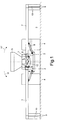
- the agricultural machine shows the elongated one in the direction of travel Support frame 1.
- At the front of the support frame 1 is that not shown Drawbar arranged for coupling to an agricultural tractor.
- At the back of the supporting frame 1 are spaced apart from one another via the supporting elements 2 the bottom 3 rolling wheels 4 anodized, over which the support frame 1 supported on the floor 3.
- the storage container 5 is on the support frame 1 arranged.
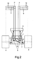
- On the back of the support frame 1, the two are by means of Joints 6 on the supporting frame 1 are arranged foldable side elements 7 arranged. These side elements 7 are by means of the hydraulic cylinder 8 from the in Fig. 1 shown working position in the transport position 7 'shown in Fig.2 swing.
- Seed coulters 9 which are assigned pressure rollers 10 or a leading bottom roller can be arranged.
- a soil cultivation device not shown, for example with Cultivator tines equipped support frame or a driven Soil cultivation machine, for example a rotary harrow.
- These tillage tools and machines are also foldable Side elements, similar to the side elements 7, arranged.
- the support frame 1 is based essentially on the from the side elements 7 arranged pressure rollers 10 or bottom roller. It there is now a risk that on a slope or on hilly or uneven terrain due to the very high center of gravity by the highly trained Storage container 5, especially when this is filled, that the machine in Depending on the terrain, work position around one of the joints 6 extending axes, as indicated by arrows 11 and 11 ', turn can. To prevent this, there is a between the side elements 7 Connecting rod 12, which is designed as a synchronous guide device, arranged.
- This connecting rod 12 is on one side frame of one Side element 7 at a distance from the folding joint 6 in a plane above the Hinged joint 6 and on the other side frame of the side element 7 in Distance to the folding joint 6 in a plane below the folding joint 6 articulated.
- This rod 12 is achieved when the support frame 1 with the Storage container 5 wants to turn around one of the axes of the joints 6 that the Side frame 7 on the bottom roller 10 arranged on the side frame 7 or pressure rollers and supports the weight of the other side frame 7 with the tools arranged thereon, such as coulters 9, pressure rollers 10 or Bottom rollers 10 must be raised with. This will stabilize reached so that a counter torque to the tilting moment is generated.
- this synchronous guide device 12 can also be used between the collapsible elements on which the tillage equipment and machines, such as a rotary harrow is arranged.
Landscapes
- Life Sciences & Earth Sciences (AREA)
- Engineering & Computer Science (AREA)
- Mechanical Engineering (AREA)
- Soil Sciences (AREA)
- Environmental Sciences (AREA)
- Agricultural Machines (AREA)
Applications Claiming Priority (2)
| Application Number | Priority Date | Filing Date | Title |
|---|---|---|---|
| DE1998135125 DE19835125A1 (de) | 1998-08-04 | 1998-08-04 | Landwirtschaftliche Arbeitsmaschine |
| DE19835125 | 1998-08-04 |
Publications (2)
| Publication Number | Publication Date |
|---|---|
| EP0978227A2 true EP0978227A2 (fr) | 2000-02-09 |
| EP0978227A3 EP0978227A3 (fr) | 2000-02-16 |
Family
ID=7876377
Family Applications (1)
| Application Number | Title | Priority Date | Filing Date |
|---|---|---|---|
| EP99113199A Withdrawn EP0978227A3 (fr) | 1998-08-04 | 1999-07-08 | Machine pour le travail d'agriculture |
Country Status (2)
| Country | Link |
|---|---|
| EP (1) | EP0978227A3 (fr) |
| DE (1) | DE19835125A1 (fr) |
Cited By (1)
| Publication number | Priority date | Publication date | Assignee | Title |
|---|---|---|---|---|
| EP2168415A1 (fr) * | 2008-09-26 | 2010-03-31 | Kuhn S.A. | Dispositif de recouvrement perfectionné |
Families Citing this family (2)
| Publication number | Priority date | Publication date | Assignee | Title |
|---|---|---|---|---|
| DE102013017901A1 (de) | 2013-10-29 | 2015-04-30 | Rauch Landmaschinenfabrik Gmbh | Landwirtschaftliche Verteilmaschine |
| DE202018104697U1 (de) | 2018-08-16 | 2019-11-20 | Rehau Ag + Co | Verbindungselement sowie dieses umfassende Rohrverbindung |
Family Cites Families (5)
| Publication number | Priority date | Publication date | Assignee | Title |
|---|---|---|---|---|
| US3866688A (en) * | 1972-12-13 | 1975-02-18 | Koehring Co | Field cultivator wing lift |
| US4342367A (en) * | 1980-10-21 | 1982-08-03 | Alloway Manufacturing, Inc. | Folding tool bar |
| EP0289864B1 (fr) * | 1987-04-22 | 1992-09-30 | H. Niemeyer Söhne GmbH & Co. KG | Machine de fenaison |
| DE4001709A1 (de) * | 1990-01-22 | 1991-07-25 | Fella Werke Gmbh | Landwirtschaftliche arbeitsmaschine |
| IT1256795B (it) * | 1992-01-31 | 1995-12-15 | Capello R & F Flli | Testata ripiegabile per la raccolata del mais, perfezionata. |
-
1998
- 1998-08-04 DE DE1998135125 patent/DE19835125A1/de not_active Withdrawn
-
1999
- 1999-07-08 EP EP99113199A patent/EP0978227A3/fr not_active Withdrawn
Non-Patent Citations (1)
| Title |
|---|
| None |
Cited By (2)
| Publication number | Priority date | Publication date | Assignee | Title |
|---|---|---|---|---|
| EP2168415A1 (fr) * | 2008-09-26 | 2010-03-31 | Kuhn S.A. | Dispositif de recouvrement perfectionné |
| FR2936394A1 (fr) * | 2008-09-26 | 2010-04-02 | Kuhn Sa | Dispositif de recouvrement perfectionne et machine agricole equipee d'un tel dispositif de recouvrement |
Also Published As
| Publication number | Publication date |
|---|---|
| EP0978227A3 (fr) | 2000-02-16 |
| DE19835125A1 (de) | 2000-02-10 |
Similar Documents
| Publication | Publication Date | Title |
|---|---|---|
| DE2351065C2 (fr) | ||
| DE2801116B2 (de) | Klappbarer Geräteträger mit zwei Werkzeugtragrahmen | |
| DE2737053B2 (de) | Landwirtschaftlich nutzbares Arbeitsgerät | |
| DE2749656C2 (fr) | ||
| DE3751912T2 (de) | Bodenbearbeitungsmaschine zur Saatbettherrichtung | |
| DE3343847C2 (fr) | ||
| DE3105639A1 (de) | "geraetekombination fuer die landwirtschaft" | |
| DE69117842T2 (de) | Bodenbearbeitungsmaschine | |
| DE2557753C2 (de) | Schlepperbetriebene Maschinenkombination | |
| DE2622649C2 (de) | Schlepperbetriebene Bodenbearbeitungsmaschine | |
| DE3017208A1 (de) | Bodenbearbeitungswalze | |
| DE3218385A1 (de) | Bodenbearbeitungsmaschine in form einer bodenfraese oder einer kreiselegge | |
| DE2528930A1 (de) | Tragrahmen fuer landwirtschaftliche maschinen und geraete | |
| DE1757445B2 (de) | Bodenbearbeitungsmaschine | |
| DE102012104699A1 (de) | Landwirtschaftliches Bodenbearbeitungsgerät | |
| EP0978227A2 (fr) | Machine pour le travail d'agriculture | |
| DE3504654C2 (fr) | ||
| DE2410290A1 (de) | Planiergeraet zur vorbereitung von landwirtschaftlichen arbeiten | |
| DE102005030923A1 (de) | Landwirtschaftsmaschine in Form einer Scheibenegge | |
| DE2559341C3 (de) | Maschine zum Ausbringen von Dänger und Saatgut | |
| DE3337193C2 (fr) | ||
| DE3430071C2 (fr) | ||
| DE1235057B (de) | Heuwerbungsmaschine mit paarweise quer zur Fahrtrichtung nebeneinander angeordneten Kreiseln | |
| DE1582167A1 (de) | Schlepperangetriebene Heuwerbungsmaschine | |
| DE69421954T2 (de) | Landwirtschaftliche Bodenbearbeitungsmaschine mit grosser Breite, die sich besser an die Bodenunebenheit anpasst |
Legal Events
| Date | Code | Title | Description |
|---|---|---|---|
| PUAI | Public reference made under article 153(3) epc to a published international application that has entered the european phase |
Free format text: ORIGINAL CODE: 0009012 |
|
| PUAL | Search report despatched |
Free format text: ORIGINAL CODE: 0009013 |
|
| AK | Designated contracting states |
Kind code of ref document: A2 Designated state(s): AT BE CH CY DE DK ES FI FR GB GR IE IT LI LU MC NL PT SE |
|
| AX | Request for extension of the european patent |
Free format text: AL;LT;LV;MK;RO;SI |
|
| AK | Designated contracting states |
Kind code of ref document: A3 Designated state(s): AT BE CH CY DE DK ES FI FR GB GR IE IT LI LU MC NL PT SE |
|
| AX | Request for extension of the european patent |
Free format text: AL;LT;LV;MK;RO;SI |
|
| AKX | Designation fees paid | ||
| STAA | Information on the status of an ep patent application or granted ep patent |
Free format text: STATUS: THE APPLICATION IS DEEMED TO BE WITHDRAWN |
|
| 18D | Application deemed to be withdrawn |
Effective date: 20000817 |