EP0978231A1 - Rundballenpresse mit Garnwickelkontrole - Google Patents
Rundballenpresse mit Garnwickelkontrole Download PDFInfo
- Publication number
- EP0978231A1 EP0978231A1 EP99202508A EP99202508A EP0978231A1 EP 0978231 A1 EP0978231 A1 EP 0978231A1 EP 99202508 A EP99202508 A EP 99202508A EP 99202508 A EP99202508 A EP 99202508A EP 0978231 A1 EP0978231 A1 EP 0978231A1
- Authority
- EP
- European Patent Office
- Prior art keywords
- twine
- bale
- strand
- rotating
- wrap
- Prior art date
- Legal status (The legal status is an assumption and is not a legal conclusion. Google has not performed a legal analysis and makes no representation as to the accuracy of the status listed.)
- Granted
Links
- 241000405070 Percophidae Species 0.000 claims abstract description 17
- 239000000463 material Substances 0.000 claims abstract description 13
- 238000005520 cutting process Methods 0.000 claims description 7
- 238000003825 pressing Methods 0.000 abstract description 3
- 238000012360 testing method Methods 0.000 description 17
- 230000007246 mechanism Effects 0.000 description 13
- 238000000034 method Methods 0.000 description 5
- 238000010586 diagram Methods 0.000 description 4
- 239000002699 waste material Substances 0.000 description 4
- 230000000977 initiatory effect Effects 0.000 description 3
- 238000003780 insertion Methods 0.000 description 3
- 230000037431 insertion Effects 0.000 description 3
- 230000015654 memory Effects 0.000 description 3
- 230000002457 bidirectional effect Effects 0.000 description 2
- 230000009471 action Effects 0.000 description 1
- 238000013459 approach Methods 0.000 description 1
- 230000015572 biosynthetic process Effects 0.000 description 1
- -1 conventional twine Substances 0.000 description 1
- 230000007257 malfunction Effects 0.000 description 1
- 238000012986 modification Methods 0.000 description 1
- 230000004048 modification Effects 0.000 description 1
- 230000002028 premature Effects 0.000 description 1
- 238000002360 preparation method Methods 0.000 description 1
- 230000008569 process Effects 0.000 description 1
- 238000005070 sampling Methods 0.000 description 1
- 238000012163 sequencing technique Methods 0.000 description 1
- 238000006467 substitution reaction Methods 0.000 description 1
Images




Classifications
-
- A—HUMAN NECESSITIES
- A01—AGRICULTURE; FORESTRY; ANIMAL HUSBANDRY; HUNTING; TRAPPING; FISHING
- A01F—PROCESSING OF HARVESTED PRODUCE; HAY OR STRAW PRESSES; DEVICES FOR STORING AGRICULTURAL OR HORTICULTURAL PRODUCE
- A01F15/00—Baling presses for straw, hay or the like
- A01F15/08—Details
- A01F15/14—Tying devices specially adapted for baling presses
- A01F15/141—Tying devices specially adapted for baling presses for round balers
-
- A—HUMAN NECESSITIES
- A01—AGRICULTURE; FORESTRY; ANIMAL HUSBANDRY; HUNTING; TRAPPING; FISHING
- A01F—PROCESSING OF HARVESTED PRODUCE; HAY OR STRAW PRESSES; DEVICES FOR STORING AGRICULTURAL OR HORTICULTURAL PRODUCE
- A01F15/00—Baling presses for straw, hay or the like
- A01F15/07—Rotobalers, i.e. machines for forming cylindrical bales by winding and pressing
- A01F15/071—Wrapping devices
- A01F2015/076—Wrapping device incorporating sensors
-
- A—HUMAN NECESSITIES
- A01—AGRICULTURE; FORESTRY; ANIMAL HUSBANDRY; HUNTING; TRAPPING; FISHING
- A01F—PROCESSING OF HARVESTED PRODUCE; HAY OR STRAW PRESSES; DEVICES FOR STORING AGRICULTURAL OR HORTICULTURAL PRODUCE
- A01F15/00—Baling presses for straw, hay or the like
- A01F15/08—Details
- A01F15/14—Tying devices specially adapted for baling presses
- A01F15/141—Tying devices specially adapted for baling presses for round balers
- A01F2015/143—Guiding fingers for twines in order to avoid the slippage of twines to the sides of the bale when tying it
Definitions
- This invention relates to agricultural balers for forming round bales of crop material and automatically wrapping the bales with twine before releasing them onto a field. More particularly, the invention relates to improvements in the twine wrapper control system to 1) improve the chances that the end of the twine will be caught up in a rotating bale at the start of a wrapping cycle and 2) provide for quick restarting of a wrapping cycle in the event the twine is not caught up.
- Typical automatic round balers such as the models 544 and 5930 commercially available from New Holland North America, pick up crop material from a field and form it into a compacted round bale in a bale forming chamber.
- bale density (or size) sensors send signals to a controller which in turn sends a signal to an operator's panel to signal the operator to stop forward motion of the baler so that the bale may be wrapped with netting or twine according to a program of instructions stored in a controller memory.
- the mechanism for wrapping with twine includes two hollow twine tubes. Two strands of twine are fed from two twine rolls through the tubes. When a wrap cycle is initiated, the twine tubes are moved arcuately to an extended or insert position with an end of one strand dangling from the end of a respective one of the tubes. A mechanism, sometimes referred to as a "duckbill", is actuated to move the dangling ends toward the bale so that the ends of the twine strands are adjacent the bale near its lengthwise middle. The strands are caught up in the bale which is rotating within the bale forming chamber. The bale is then wrapped in a pattern by moving the twine tubes toward a home position with programmed pauses at intervals to place circular wraps on the bale. The twine is cut after end wraps have been placed on the bale.
- each twine strand slides into a spring clamp and hold device so that the twine ends can not be caught up in moving machine parts after the strands are cut.
- Each twine is pulled out of its respective clamp and hold device at the beginning of the next wrap cycle as the twine tube arms are extended to the insert position.
- the pattern in which the bale is wrapped is determined by a stored program in the controller.
- This program may be a factory-installed program, a "learned" program generated by manually controlling movement of the twine tubes to place the desired wrap pattern on a bale, or a factory-installed program which permits operator selection of the number of end wraps to be placed on a bale.
- the programs provide no easy method for restarting a twine wrap cycle to re-tie a bale in the event one or both strand ends are not caught up in the rotating bale.
- the operator may wait until the selected twine pattern program completes its automatic wrap cycle and then restart the wrap cycle by actuating, for two seconds, a Wrap key on an operator's control panel. This procedure wastes a considerable amount of twine if one twine was caught up in the rotating bale.
- the operator could manually return the twine tubes to their home position by 1) actuating a Retract key on the operator's control panel to retract the twine tubes to their home position, 2) switching the controller to the net wrap mode by actuating a Net/Twine key, 3) again actuating the Retract key to return the duckbill to the home position and cut the twine, 4) actuating a Clear key to clear the error alarm and error message displayed on the operator's control panel (caused by interruption of the wrap cycle), 5) actuating the Net/Twine key to return the controller to the twine mode, and 6) initiating a new wrap cycle by actuating the Wrap key for two seconds.
- This complex procedure would require a very skilled and knowledgeable operator and wastes considerable time. It also wastes twine if one strand is started but, as compared to the first procedure, results in less waste.
- bale wrapping system for wrapping a rotating bale of crop material with at least one strand of twine, said bale wrapping system comprising:
- Said system is characterized in that said controller is operable to move said twine dispensing arm to said twine insert position before said sensed bale parameter reaches said desired value.
- the controller may react to the actual bale parameter sensed for initiating movement of the twine arm as soon as the parameter reaches a percentage of the desired value.
- the twine arm may move to the insert position when 50 % of the desired density is reached.
- the introduction means hold the strand adjacent the rotating bale for a predetermined time interval, thereby increasing the chance that the twine is seized and entrained by the rotating bale.
- the system may further comprise clamp and stop means for releasably gripping the strand while the dispensing arm is in its home position, before the cutting operation takes place.
- the cutting operation may be performed by a knife assembly driven by the twine introduction means. When the latter is moved to its home position the cutting assembly is actuated to cut the strand or strands.
- the controller is responsive to actuation of a wrap key to abort a wrapping cycle and initiate a new wrapping cycle. Then the operator does not have to wait for the completion of the missed cycle, with the ensuing loss of twine and time, but he can almost immediately resume the wrapping operation.
- the restart cycle advantageously comprises returning the dispensing arm to its home position and cutting the twine, moving the arm back to the insert position and moving the introduction means to push the twine to the bale.
- the arm may be held in the home position for a predetermined time interval to allow the twine to be grasped by the clamp and stop means. Accordingly, in the event of a malfunction during a wrapping cycle the twine is cut, the system restored to an initial state and a new wrapping cycle initiated by merely actuating a Wrap key on an operator's control panel.
- the controller may comprise a programmable microprocessor.
- the system comprises a pair of dispensing arms in the form of tubes.
- the introduction means may comprise a duckbill which is also operable to present net or wrapping film to the bale.
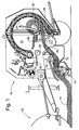
- FIG. 1 schematically illustrates a baler 10 such as the New Holland model 544 automatic round baler which is adapted to be pulled by, and powered from, a tractor 12.
- a pick-up assembly 14 having cross conveying augers (not shown), picks up crop material 16 and feeds it via a feed rotor 18 and a rotating floor roll 20 into a bale forming chamber 22.
- the crop material at first curls freely under the combined action of the floor roll 20, a chain conveyor 24 and a rotating stripper roll 26, and packs loosely under its own weight until chamber 22 is filled.
- the crop material is compacted and exerts a force against a tailgate 28 tending to open the tailgate.
- the tailgate is hooked up by a tailgate latch 30 attached to the main frame of the baler and a density cylinder 32 is attached to the tailgate.
- the tailgate 28 is allowed to release slightly but is still held in latch 30 so that pressure exerted on the tailgate by the bale pulls on and extends cylinder 32 against the pressure in the gas accumulator on the cylinder.
- Two latch sensor switches 31, 33 ( Figure 6) are provided, one switch at each side of the baler, to detect when the tailgate is latched.
- the desired bale density is set by an operator by actuating Bale Size, "+" and "-" keys 300, 301 and 302 on an operator's keyboard or control panel 34 (Figure 8).
- Two bale density sensors 36 are provided, one at each side of the baler.
- the sensors include respective potentiometers 38, 40 ( Figure 6) for producing electrical analog signals indicating the sensed density.
- a controller 42 includes a microprocessor 46 which first converts the analog signals to digital values and then compares the sensed density with the desired bale density. When the two are equal the operator is signaled to stop forward motion of the baler by energizing an audible signal generator 304 and a "full bale” indicator light 306 on the operator's control panel 34.
- the controller waits a short interval (say 0.75 second) to allow to the operator the time to stop forward motion of the baler and then automatically initiates a bale wrapping cycle to wrap the bale with net or twine depending on which wrapping material the operator has selected by operation of a Net/Twine key 312 ( Figure 8).
- a short interval say 0.75 second
- twine as used herein means any suitable strand-like material such as conventional twine, plastic material and wire.
- the controller 42 includes a converter circuit (not shown) for converting a +12V battery voltage from a source 49 to +5V for powering the microprocessor, the source voltage being routed to the converter through an on/off switch controlled from an On/Off key 310 on the operator's control panel 34.
- the controller 42 also includes an actuator selector relay 44 and driver circuits 45 and 47 controlled by microprocessor 46 to selectively energize a bidirectional twine wrap actuator drive motor 48 or a bidirectional net wrap actuator drive motor 50.
- Relay 44 and drivers 45 and 47 provide a current for driving either motor in two opposite directions.
- the microprocessor 46 is conventional and includes ROM, RAM and EPROM memories and an analog to digital converter in addition to a digital processor.
- the microprocessor is connected to the operator's control panel by three leads, one lead (CLK) carrying clock pulses to the control panel, one lead (D2) carrying data signals to the control panel and one lead (D1) carrying data signals from the control panel to the microprocessor.
- the microprocessor periodically samples lead D1 to determine if any key has been actuated and stores a flag or indication in a register or memory when a key is actuated.
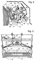
- FIGs 2 and 3 illustrate the wrapping mechanism for wrapping a rotating bale 52 with net from a supply roll 54 or with twine from two supply rolls 56, only one of the supply rolls being visible in Figure 2.
- the wrapping mechanism comprises a net wrap actuator 58 driven by the net wrap actuator drive motor 50, a duckbill 60 mounted on a pivot 62, a twine wrap actuator 64 driven by the twine wrap actuator drive motor 48 ( Figures 3 and 6), and two arms comprising hollow twine tubes 68 driven by actuator 64 via gearing 66.
- the wrapping mechanism further includes two spring clamp and stop devices 70 for releasably gripping a respective strand of twine 72, a knife assembly 74 pivoted at 76 and connected to duckbill 60 by a linkage 78, and a shear bar 80 cooperating with knife assembly 74 to cut the twine.
- the clamp and stop devices are adjustable laterally as viewed in Figure 3 to thereby adjust the location of end wraps of twine placed on the bale 52.
- a sensor 82 ( Figure 3) is mounted on the twine wrap actuator 64 and includes a potentiometer 84 ( Figure 6) for producing a signal indicating the position or extension of the twine wrap actuator.
- a potentiometer 86 ( Figure 6) is provided for producing a signal indicating the position or extension of the net wrap actuator 58.
- Figures 2 and 3 illustrate the wrapping mechanism in the "home" position, that is, when the net wrap actuator 58 and the twine wrap actuator 64 are fully retracted.
- Figures 4 and 5 show the wrapping mechanism in a twine inserting position with both actuators fully extended.
- the twine wrap actuator 64 is extended prior to the time a complete bale is formed.
- the twine wrap actuator drives the twine tubes 68 from the home position ( Figure 3) to a twine inserting position ( Figure 5).
- the twine strands 72 are pulled free of the clamp and stop devices 70 so as to dangle freely from the ends of the tubes.
- the net wrap actuator 58 is extended. As the net wrap actuator extends, it pivots duckbill 60 clockwise from the position shown in Figure 2 to that shown in Figure 4.
- the duckbill via linkage 78, pivots the knife assembly 74 counter-clockwise so that the knife assembly is spaced from the shear bar 80. Further pivoting of the duckbill 60 causes it to engage the dangling twine strands 72, pushing them over the rotating stripper roll 26. The strands are caught up in the rotating bale and begin to wrap around the bale.
- the net wrap actuator is retracted to a "precut position". In this position the duckbill 60 is clear of the twine strands but the knife assembly 74 is still spaced from the shear bar 80.
- the twine wrap actuator 64 dwells at the fully extended position for a programmed interval to time to place a programmed number of circular wraps on the center of the bale. The twine wrap actuator is then retracted toward its home position, pausing as specified by the program to place circular wraps on the bale. As the twine wrap actuator approaches its home position the twine strands 72 slide into the clamp and stop devices 70 and a programmed number of end wraps are placed on the bale 52. After a programmed lapse of time to permit placement of the end wraps, the net wrap actuator 58 is retracted from its precut position to its home position.
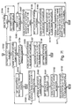
- Figures 7a-7g comprise a flow diagram of the program routine executed by microprocessor 46 ( Figure 6) to cycle the net and twine wrap actuators as described above and, in the event one or both twine strands 72 are not caught up in the bale, immediately terminating the wrapping cycle and initiating a re-tie cycle if the operator actuates a Wrap key 314 ( Figure 8).
- the routine is called at about 32.7 ms intervals from a main routine.
- S100 step 100
- a test is made to determine if the operator has operated Net/Twine key 312 so as to select the twine wrap mode. If not, a return is made to the main routine but if the twine wrap mode has been selected an Initialize flag is tested at S101.
- the Initialize flag On the first execution of the routine after the system is powered up, the Initialize flag will be in the reset condition when tested at S101.
- the flag is set at S102 and the microprocessor 46 energizes via line 43 the actuator selector relay 44 ( Figure 6) to select the twine wrap actuator motor 48 ( Figure 6) for energization.
- drivers 45 and 47 are not enabled to drive the motor.
- the tailgate switches 31, 33 are tested and if the tailgate is open all flags, except the Initialize flag and various, counters and timers are reset or initialized at S104 before a return is made to the main routine. Thereafter, S100, S101, S103 and S104 are repeated until the tailgate 28 is closed.
- S105 is executed on the first execution of the routine where S103 determines that the tailgate is closed. This step tests an Auto Extend Done Flag and also compares the present bale density with a density value equal to 50% of the bale density value selected by the operator. The present bale density is determined in a separate routine by sampling the outputs of the bale sensor potentiometers 38 and 40 and the computed present bale density value is saved so that it is available for use at S105.
- the Auto Extend Done flag is not set.
- the present bale density will be less than 50% of the operator selected bale density so the routine jumps from S105 to S110 which tests a Wrap Complete/Eject Bale flag to determine if it has been set. This flag has not yet been set so a Full Bale-Wrap Enable flag is tested at S111 to determine if it has been set. This flag has not been set so a return is made to the main routine.
- the routine is periodically repeated, executing S100, S101, S103, S105 and S110-111. Eventually the bale density reaches 50% of the bale density selected by the operator. This condition is detected at S105 and since the Auto Extend Done Flag is not set the routine advances to S106 where the output of the twine actuator sensor potentiometer 84 is sampled to determine if the twine actuator 64 is extended to the twine insert position. Since the twine actuator is still in the home position, S107 is executed to set drivers 45 and 47 to energize the twine actuator drive motor 48 to begin moving the twine actuator toward the twine insertion position. The routine then returns to the main routine.
- the routine repetitively executes S100, S101, S103 and S105-S107.
- the twine actuator reaches its twine insertion position, this is detected at S106 and at S108 the drivers 45, 47 are turned off.
- the Auto Extend Done flag is then turned on at S109 and S110 and S111 are executed. Since the Full Bale/Wrap Enable flag is still not set, the wrap routine returns from S111 to the main program.
- S100, S101, S103, S105, S110 and S111 are periodically repeated as the bale continues to build up. This continues until the subroutine mentioned above determines that a full bale has been formed and sets the Full Bale/Wrap Enable flag.
- S111 detects that the flag is set. The routine advances to S112 to test for a set condition of the Auto Extend Done flag. Since this flag has been set the routine advances to S113 in Figure 7b.
- S113 tests a Twine Inserted Flag and, since it has not yet been set, S114 is executed to determine if a Restart Wrap Cycle flag has been set.
- the Wrap Cycle Restart flag has not been set, so at S115 the output of the net actuator position sensor potentiometer 86 is sampled to determine if the net actuator is at its twine insert position.
- the net actuator is still in its home position, so at S116 the actuator selector relay is deenergized and at S117 drivers 45 and 47 are turned on to energize the net actuator drive motor 50 to drive the net actuator 58 toward its twine insert position. A return is then made to the main routine.
- a delay of one second is provided after the net actuator reaches its insert position to allow the twine to be caught up in the rotating bale.
- the timer is tested at S119 to determine if it has been set and since it is not initially set, it is set at S120 and tested at S121 to determine if it has tolled the 1-second interval. Since the timer has just been set, the test at S121 will initially determine that the interval has not elapsed so a return is made to the main routine.
- the routine repeats S101, S103, S105, S110-S115 and S118-S121.
- the first execution of S121 following expiration of the 1-second interval detects that the interval has expired.
- Drivers 45 and 47 are set at S122 to begin driving the net actuator drive motor 50 to move the net actuator to its precut position, and the Twine Inserted flag is set at S123.
- the net actuator is still moving toward the precut position when S128 is executed, so the routine returns to the main program. While the net actuator is moving toward its precut position the wrap routine executes S100, S101, S103, S105, S110-S113 and S124-S128 on each repetition. S128 detects when the net actuator has reached its precut position and the routine advances to S129 which turns off the drivers 45 and 47, thus stopping the net actuator 58.
- the Insert Twine Cycle Done flag is set at S130 and at S131 the net/twine actuator relay 44 is energized to select the twine actuator drive motor 48 for energization when drivers 45, 47 are next turned on.
- S133 tests the event counter associated with the pattern program to determine if it is equal to the last pattern program step count. As long as the event counter is not equal to the last step count, the wrap routine returns to the main program from S133 but when the event counter is equal to the last step count, the Retract To Cut Flag is set at S134.
- the net/twine actuator selector relay 44 is then de-energized during S135 to select the net actuator drive motor 50 for energization and S136 sets drivers 45 and 47 so that the motor is energized to drive the net actuator 58 toward its home position. This pivots the duckbill 60 toward its home position and the duckbill drives knife assembly 74 to cut the twine.
- the wrap routine then returns to the main program.
- S101, S103, S105, S110-S113, S124-S126 and S137 are repeated until the net actuator 58 reaches it home position. This is detected at S137 and the routine advances to S138 which turns off the drivers 45 and 47 to stop the net actuator. S139 then sets the Wrap Complete/Eject Bale flag and S140 clears the Twine Inserted flag, the Full Bale Enable flag and the event counter. Finally, in preparation for the next bale wrapping cycle, S141 energizes the actuator selector relay 44 to set it for the twine actuator drive motor 48. This completes the wrapping cycle. On the next execution of the routine, when S110 ( Figure 7a) is reached, the test of the Wrap Complete/Eject Bale flag finds that the flag is now set so the wrap routine returns to the main program.
- S100, S101, S103, S105 and S110 are repeated each time the wrap routine is entered. Normally, this continues until the tailgate 28 is opened, at which time S103 detects that the tailgate switches 31, 33 are not closed and S104 clears all flags used in the routine.
- the test at S124 finds that the Restart Wrap Cycle flag is set and the routine branches to S152 ( Figure 7f) which tests to determine if the Retract To Cut Twine flag is set. Since the latter flag has been cleared, S153 tests to see if a Twine Actuator Return Home flag is set. This flag has not been set, so at S154 the output of the net actuator position sensor potentiometer 86 is sampled to determine if the net actuator 58 is at its precut position. If S154 determines that the net actuator is not at its precut position, it means that the net actuator is in the process of retracting to that position. The routine returns to the main program.
- the wrap routine is periodically executed and the output of the net actuator position sensor potentiometer is sensed at S154. This continues until S154 determines the net actuator has reached its precut position.
- the drivers 45, 47 are then turned off at S156 to stop the net actuator and the net/twine selector relay 44 is energized at S157 to select the twine actuator drive motor for energization.
- the Twine Actuator Return Home flag is the set at S158 and the routine returns to the main program.
- the wrap routine is periodically executed while the twine actuator 64 is returning to its home position and the output of potentiometer 84 is sampled at S160 on each execution. This continues until S160 determines that the twine actuator is in its home position.
- the routine then advances to S161 where the Retract To Cut flag is set.
- S162 then turns off the drivers 45 and 47 to stop the twine actuator and S163 de-energizes relay 44 to select the net actuator drive motor 50.
- the routine then returns to the main program.
- the routine is periodically executed while the net actuator 58 is returning to its home position and on each execution S168 tests to determine if this position has been reached.
- S168 determines that the net actuator is in its home position the routine advances to S169 where the drivers 45 and 47 are turned off to stop it.
- S170 then energizes the net/twine selector relay to set it for energizing the twine actuator drive motor 48.
- S171 then clears the Twine Inserted flag, Retract To Cut flag, Twine Actuator Return Home flag, and Insert Twine Cycle Done flag, as well as the event counter and various timers.
- the routine then returns to the main program.
- S113 Figure 7b detects that the Twine Inserted flag is reset.
- the routine advances to S114 and since the Restart Wrap Cycle flag is still set the routine branches to S172 ( Figure 7g) where the output of potentiometer 84 is sampled to determine if the twine actuator 64 is at the insert position. Since the twine actuator is in its home position, the routine advances from S172 to S173 where drivers 45 and 47 are turned on to extend the twine actuator. The routine then returns to the main program.
- the wrapping mechanism is now ready to restart the aborted wrap cycle.
- the twine actuator is at its insert position and the net actuator in its home position.
- S100, S101, S103, S105, S110-S117 are executed with S117 turning on drivers 45 and 47 to drive the net actuator toward its twine insert position. Sequencing then continues as described above.
Landscapes
- Life Sciences & Earth Sciences (AREA)
- Environmental Sciences (AREA)
- Preliminary Treatment Of Fibers (AREA)
- Spinning Or Twisting Of Yarns (AREA)
Applications Claiming Priority (2)
| Application Number | Priority Date | Filing Date | Title |
|---|---|---|---|
| US9503898P | 1998-08-03 | 1998-08-03 | |
| US95038P | 1998-08-03 |
Publications (2)
| Publication Number | Publication Date |
|---|---|
| EP0978231A1 true EP0978231A1 (de) | 2000-02-09 |
| EP0978231B1 EP0978231B1 (de) | 2004-04-07 |
Family
ID=22248894
Family Applications (1)
| Application Number | Title | Priority Date | Filing Date |
|---|---|---|---|
| EP99202508A Expired - Lifetime EP0978231B1 (de) | 1998-08-03 | 1999-07-30 | Rundballenpresse mit Garnwickelkontrole |
Country Status (3)
| Country | Link |
|---|---|
| US (1) | US6209450B1 (de) |
| EP (1) | EP0978231B1 (de) |
| DE (1) | DE69916184T2 (de) |
Cited By (9)
| Publication number | Priority date | Publication date | Assignee | Title |
|---|---|---|---|---|
| FR2845562A1 (fr) * | 2002-09-18 | 2004-04-16 | Lely Maschinenfabrik Gmbh | Presse a balles rondes equipee d'au moins deux systemes de liage |
| CN102781221A (zh) * | 2010-02-12 | 2012-11-14 | Cnh比利时股份有限公司 | 一种方形压捆机及相关的控制方法 |
| GB2529381A (en) * | 2014-06-20 | 2016-02-24 | Kuhn Geldrop Bv | Baler apparatus |
| EP3000311A1 (de) | 2014-09-26 | 2016-03-30 | CNH Industrial Belgium nv | Ballenumwicklungsvorrichtung für eine rundballenpresse |
| EP2700297A3 (de) * | 2012-08-21 | 2016-09-14 | CNH Industrial Belgium nv | Stromabtastung von Stellgliedern auf einer Rundballenpresse |
| EP3090622A1 (de) * | 2015-05-04 | 2016-11-09 | PÖTTINGER Landtechnik GmbH | Ballenpresse für landwirtschaftliches erntegut |
| WO2022024102A1 (en) * | 2020-07-30 | 2022-02-03 | Mchale Engineering | A baler and method and apparatus for determining uniformity of the density of a round bale |
| US20230363317A1 (en) * | 2022-05-11 | 2023-11-16 | Cnh Industrial America Llc | Agricultural system for bale appearance assessment |
| EP4494454A1 (de) * | 2023-07-19 | 2025-01-22 | McHale Engineering Unlimited Company | Ballenpresse |
Families Citing this family (28)
| Publication number | Priority date | Publication date | Assignee | Title |
|---|---|---|---|---|
| US6446548B2 (en) * | 1998-08-03 | 2002-09-10 | New Holland North America, Inc. | Round baler twine wrap control with automatic restart |
| DE10125569A1 (de) * | 2001-05-25 | 2002-11-28 | Deere & Co | Rundballenpresse |
| US6644006B1 (en) | 2002-07-19 | 2003-11-11 | New Holland North America, Inc. | Remote reverse control for pick-up rotor |
| US6981352B2 (en) * | 2002-07-26 | 2006-01-03 | Cnh America Llc | Round baler low net indication |
| US6681688B1 (en) | 2002-09-13 | 2004-01-27 | New Holland North America, Inc. | Round baler with self aligning knives for twine wrapper |
| US6763761B1 (en) | 2003-02-28 | 2004-07-20 | New Holland North America, Inc. | Wiper for twine knife striker plate |
| US6769353B1 (en) | 2003-02-28 | 2004-08-03 | New Holland North America, Inc. | Four twine tube round baler twine system |
| DE10312897B4 (de) * | 2003-03-22 | 2019-09-05 | Deere & Company | Vorrichtung zum Umhüllen eines Ballens mit einer Hüllbahn und Ballenpresse |
| US7409814B2 (en) * | 2004-09-07 | 2008-08-12 | Vermeer Manufacturing Company | Method of initiating automatic feed of bale wrapping material |
| US7337713B1 (en) * | 2006-08-01 | 2008-03-04 | Agco Corporation | Bale wrapping pattern controller and method |
| DE102007032859A1 (de) * | 2007-07-12 | 2009-01-15 | Claas Selbstfahrende Erntemaschinen Gmbh | Ballenpresse mit Bindematerialversorgung |
| US7490544B1 (en) | 2007-09-20 | 2009-02-17 | Vermeer Manufacturing Company | Twin twine arm for a baler |
| US7918072B2 (en) * | 2008-10-10 | 2011-04-05 | Cnh America Llc | Mechanical net wrapper |
| DE102009002439A1 (de) * | 2008-11-19 | 2010-05-20 | Deere & Company, Moline | Anordnung und Verfahren zum Umwickeln eines Ballens |
| US8434289B2 (en) * | 2009-05-12 | 2013-05-07 | Cnh America Llc | Sensor for detection of wrapping on bale |
| BE1018853A3 (nl) * | 2009-08-10 | 2011-10-04 | Cnh Belgium Nv | Een balenpers met een verbeterde stripper rol. |
| BE1019619A3 (nl) * | 2009-09-17 | 2012-09-04 | Cnh Belgium Nv | Een rechthoekige balenpers met een stuureenheid. |
| US8429881B2 (en) * | 2009-09-18 | 2013-04-30 | Agco Corporation | Baler starter roll |
| US8011295B1 (en) | 2010-04-08 | 2011-09-06 | Cnh America Llc | Fully automated twine wrapping system for a round baler having a simplified operator interface |
| US9560808B2 (en) | 2011-04-19 | 2017-02-07 | Cnh Industrial America Llc | System for controlling bale forming and wrapping operations |
| WO2013106197A1 (en) * | 2011-12-22 | 2013-07-18 | Agco Corporation | Round baler wrapping with multiple stationary strands |
| EP2835046B1 (de) * | 2013-08-05 | 2017-03-01 | Kverneland Group Ravenna S.r.l. | Vorrichtung zur Verarbeitung von Ballen für landwirtschaftliche Maschinen |
| US11134614B2 (en) * | 2018-10-10 | 2021-10-05 | Deere & Company | Productivity increase for a round baler |
| US11533853B2 (en) | 2019-09-12 | 2022-12-27 | Cnh Industrial America Llc | Agricultural vehicle with automatic motor-driven component calibration |
| USD951403S1 (en) | 2019-12-04 | 2022-05-10 | Sloan Valve Company | Valve |
| IT202000004612A1 (it) * | 2020-03-04 | 2021-09-04 | Cnh Ind Italia Spa | Imballatrice agricola con coltello per materiale di avvolgimento per ridurre l'avvolgimento sul rotore |
| EP4091434A1 (de) * | 2021-05-10 | 2022-11-23 | AGCO International GmbH | Ballenpressvorrichtung |
| CN113498669A (zh) * | 2021-09-13 | 2021-10-15 | 潍坊科技学院 | 一种畜牧养殖用干草打捆用捆绑装置及其工作方法 |
Citations (4)
| Publication number | Priority date | Publication date | Assignee | Title |
|---|---|---|---|---|
| EP0117817A1 (de) * | 1983-02-28 | 1984-09-05 | Regie Nationale Des Usines Renault | Vorrichtung zum automatischen Steuern der Bandeinrichtung für Rundballenpressen |
| EP0159048A2 (de) * | 1981-09-17 | 1985-10-23 | Deere & Company | Automatische Bindeeinrichtung für Maschinen zum Herstellen von zylindrischen Ballen aus Erntegut in einer Wickelkammer |
| EP0181969A1 (de) * | 1984-11-21 | 1986-05-28 | Ford New Holland N.V. | Automatische Bindevorrichtung für Rundballenpressen |
| US5581974A (en) * | 1995-10-02 | 1996-12-10 | New Holland North America, Inc. | Dual purpose cutting apparatus for round bale |
Family Cites Families (11)
| Publication number | Priority date | Publication date | Assignee | Title |
|---|---|---|---|---|
| FR2488770A1 (fr) * | 1980-08-20 | 1982-02-26 | Deere John Cie Francaise | Dispositif de liage pour presses a balles cylindriques |
| DE3414080A1 (de) * | 1984-04-13 | 1985-10-24 | Klöckner-Humboldt-Deutz AG Zweigniederlassung Fahr, 7702 Gottmadingen | Vorrichtung zum binden von rollballen aus landwirtschaftlichem erntegut |
| US4674403A (en) * | 1985-08-27 | 1987-06-23 | New Holland Inc. | Semi-automatic baler control and indicator system |
| US4627340A (en) * | 1985-10-16 | 1986-12-09 | New Holland Inc. | Twine wrapping apparatus with trip mechanism actuated twine dispensing member |
| FR2606966B1 (fr) * | 1986-11-21 | 1990-04-27 | Hesston Sa | Presse a balles cylindriques automatisee |
| US5152123A (en) * | 1989-12-27 | 1992-10-06 | Deere & Company | Indicator system for alerting an operator to the condition of a large cylindrical bale wrapping mechanism |
| US5631826A (en) * | 1992-01-16 | 1997-05-20 | New Holland North America, Inc. | Round baler end wrap control |
| US5231828A (en) * | 1992-02-26 | 1993-08-03 | M & W Gear Company | Wrapping mechanism for round balers |
| US5388504A (en) * | 1993-08-23 | 1995-02-14 | Agco Corporation | Twine wrap control for round baler |
| US5551218A (en) * | 1994-09-19 | 1996-09-03 | Gehl Company | Round baler monitoring and control system |
| US6050052A (en) * | 1998-06-17 | 2000-04-18 | Hay & Forage Industries | Round baler having positive start wrapper dispensing mechanism |
-
1999
- 1999-07-29 US US09/362,723 patent/US6209450B1/en not_active Expired - Lifetime
- 1999-07-30 DE DE69916184T patent/DE69916184T2/de not_active Expired - Lifetime
- 1999-07-30 EP EP99202508A patent/EP0978231B1/de not_active Expired - Lifetime
Patent Citations (4)
| Publication number | Priority date | Publication date | Assignee | Title |
|---|---|---|---|---|
| EP0159048A2 (de) * | 1981-09-17 | 1985-10-23 | Deere & Company | Automatische Bindeeinrichtung für Maschinen zum Herstellen von zylindrischen Ballen aus Erntegut in einer Wickelkammer |
| EP0117817A1 (de) * | 1983-02-28 | 1984-09-05 | Regie Nationale Des Usines Renault | Vorrichtung zum automatischen Steuern der Bandeinrichtung für Rundballenpressen |
| EP0181969A1 (de) * | 1984-11-21 | 1986-05-28 | Ford New Holland N.V. | Automatische Bindevorrichtung für Rundballenpressen |
| US5581974A (en) * | 1995-10-02 | 1996-12-10 | New Holland North America, Inc. | Dual purpose cutting apparatus for round bale |
Cited By (12)
| Publication number | Priority date | Publication date | Assignee | Title |
|---|---|---|---|---|
| FR2845562A1 (fr) * | 2002-09-18 | 2004-04-16 | Lely Maschinenfabrik Gmbh | Presse a balles rondes equipee d'au moins deux systemes de liage |
| DE10243295A1 (de) * | 2002-09-18 | 2004-05-19 | Lely Maschinenfabrik Gmbh | Rundballenpresse |
| DE10243295B4 (de) * | 2002-09-18 | 2010-11-11 | Welger Maschinenfabrik Gmbh | Rundballenpresse |
| CN102781221A (zh) * | 2010-02-12 | 2012-11-14 | Cnh比利时股份有限公司 | 一种方形压捆机及相关的控制方法 |
| EP2700297A3 (de) * | 2012-08-21 | 2016-09-14 | CNH Industrial Belgium nv | Stromabtastung von Stellgliedern auf einer Rundballenpresse |
| GB2529381A (en) * | 2014-06-20 | 2016-02-24 | Kuhn Geldrop Bv | Baler apparatus |
| US11277971B2 (en) | 2014-06-20 | 2022-03-22 | Kuhn-Geldrop Bv | Agricultural baler including a bale chamber with a low traction rotary compression element |
| EP3000311A1 (de) | 2014-09-26 | 2016-03-30 | CNH Industrial Belgium nv | Ballenumwicklungsvorrichtung für eine rundballenpresse |
| EP3090622A1 (de) * | 2015-05-04 | 2016-11-09 | PÖTTINGER Landtechnik GmbH | Ballenpresse für landwirtschaftliches erntegut |
| WO2022024102A1 (en) * | 2020-07-30 | 2022-02-03 | Mchale Engineering | A baler and method and apparatus for determining uniformity of the density of a round bale |
| US20230363317A1 (en) * | 2022-05-11 | 2023-11-16 | Cnh Industrial America Llc | Agricultural system for bale appearance assessment |
| EP4494454A1 (de) * | 2023-07-19 | 2025-01-22 | McHale Engineering Unlimited Company | Ballenpresse |
Also Published As
| Publication number | Publication date |
|---|---|
| DE69916184T2 (de) | 2004-08-12 |
| DE69916184D1 (de) | 2004-05-13 |
| EP0978231B1 (de) | 2004-04-07 |
| US6209450B1 (en) | 2001-04-03 |
Similar Documents
| Publication | Publication Date | Title |
|---|---|---|
| EP0978231B1 (de) | Rundballenpresse mit Garnwickelkontrole | |
| US6446548B2 (en) | Round baler twine wrap control with automatic restart | |
| US4624179A (en) | Automatic control device for tying in a hay baler | |
| US5388504A (en) | Twine wrap control for round baler | |
| US4656930A (en) | Method of wrapping round bales | |
| US5551218A (en) | Round baler monitoring and control system | |
| EP1584227B1 (de) | Doppelknotensystem für landwirtschaftliche Ballenpresse | |
| EP0443697B1 (de) | Rundballenpresse mit einer kontinuierlichen Angabe der Ballengrösse | |
| EP0215513A1 (de) | Halbautomatisches Steuer- und Anzeigesystem für Grossballenpressen | |
| US8011295B1 (en) | Fully automated twine wrapping system for a round baler having a simplified operator interface | |
| US4248143A (en) | Interlacing twine wrapping mechanism for rotary balers | |
| EP2883440B1 (de) | Automatische Anhaltesequenz für Ballenpressen | |
| US7918072B2 (en) | Mechanical net wrapper | |
| EP1734806A1 (de) | Vorrichtung zum umhüllen eines grasballens oder dergleichen | |
| GB1600417A (en) | Knotters | |
| EP0040970B1 (de) | Vorrichtung, um Fehler des Bindesystems einer Presse anzuzeigen | |
| EP0856248B1 (de) | Knüpferüberwachungseinrichtung für Ballenpresse | |
| EP3188586B1 (de) | Ballenpresse mit automatisierter auswahl von auswerferzähnen | |
| EP0857414A1 (de) | Vorrichtung zur Regelung des Pressdruckes einer Strohballenpresse | |
| WO2012092313A1 (en) | Intelligent stuffer mechanism for baler | |
| US20210337738A1 (en) | Tying Device for an Agricultural Crop Press and Agricultural Crop Press with Such a Tying Device | |
| GB2053079A (en) | Twine actuated cutter in a rotary crop baler | |
| CA2010212C (en) | Method and apparatus for density control in rectangular balers to improve the bale tying operation | |
| EP0077141A1 (de) | Knüpfer | |
| WO2001056363A1 (en) | Method and apparatus for controlling knife position in a round chopper, baler based on a physical characteristic |
Legal Events
| Date | Code | Title | Description |
|---|---|---|---|
| PUAI | Public reference made under article 153(3) epc to a published international application that has entered the european phase |
Free format text: ORIGINAL CODE: 0009012 |
|
| AK | Designated contracting states |
Kind code of ref document: A1 Designated state(s): DE FR GB IT NL |
|
| AX | Request for extension of the european patent |
Free format text: AL;LT;LV;MK;RO;SI |
|
| 17P | Request for examination filed |
Effective date: 20000802 |
|
| AKX | Designation fees paid |
Free format text: DE FR GB IT NL |
|
| 17Q | First examination report despatched |
Effective date: 20020916 |
|
| RAP1 | Party data changed (applicant data changed or rights of an application transferred) |
Owner name: CNH BELGIUM N.V. |
|
| GRAP | Despatch of communication of intention to grant a patent |
Free format text: ORIGINAL CODE: EPIDOSNIGR1 |
|
| RIN1 | Information on inventor provided before grant (corrected) |
Inventor name: CLAEYS, DANNY N. O. Inventor name: VANDE RYSE, JOHAN A. E. Inventor name: VANDAMME, DIRK A. R. Inventor name: CHOW, MARK K. Inventor name: NAAKTGEBOREN, ADRIANUS Inventor name: VAN GROENIGEN, JAN C. |
|
| GRAS | Grant fee paid |
Free format text: ORIGINAL CODE: EPIDOSNIGR3 |
|
| GRAA | (expected) grant |
Free format text: ORIGINAL CODE: 0009210 |
|
| AK | Designated contracting states |
Kind code of ref document: B1 Designated state(s): DE FR GB IT NL |
|
| PG25 | Lapsed in a contracting state [announced via postgrant information from national office to epo] |
Ref country code: NL Free format text: LAPSE BECAUSE OF FAILURE TO SUBMIT A TRANSLATION OF THE DESCRIPTION OR TO PAY THE FEE WITHIN THE PRESCRIBED TIME-LIMIT Effective date: 20040407 |
|
| REG | Reference to a national code |
Ref country code: GB Ref legal event code: FG4D |
|
| REF | Corresponds to: |
Ref document number: 69916184 Country of ref document: DE Date of ref document: 20040513 Kind code of ref document: P |
|
| NLV1 | Nl: lapsed or annulled due to failure to fulfill the requirements of art. 29p and 29m of the patents act | ||
| ET | Fr: translation filed | ||
| PLBE | No opposition filed within time limit |
Free format text: ORIGINAL CODE: 0009261 |
|
| STAA | Information on the status of an ep patent application or granted ep patent |
Free format text: STATUS: NO OPPOSITION FILED WITHIN TIME LIMIT |
|
| 26N | No opposition filed |
Effective date: 20050110 |
|
| REG | Reference to a national code |
Ref country code: GB Ref legal event code: 746 Effective date: 20090114 |
|
| PGFP | Annual fee paid to national office [announced via postgrant information from national office to epo] |
Ref country code: DE Payment date: 20130709 Year of fee payment: 15 |
|
| PGFP | Annual fee paid to national office [announced via postgrant information from national office to epo] |
Ref country code: GB Payment date: 20130705 Year of fee payment: 15 Ref country code: FR Payment date: 20130730 Year of fee payment: 15 |
|
| REG | Reference to a national code |
Ref country code: DE Ref legal event code: R082 Ref document number: 69916184 Country of ref document: DE Representative=s name: G. KOCH UND KOLLEGEN, DE |
|
| REG | Reference to a national code |
Ref country code: DE Ref legal event code: R082 Ref document number: 69916184 Country of ref document: DE Representative=s name: G. KOCH UND KOLLEGEN, DE Effective date: 20140428 Ref country code: DE Ref legal event code: R081 Ref document number: 69916184 Country of ref document: DE Owner name: CNH INDUSTRIAL BELGIUM NV, BE Free format text: FORMER OWNER: CNH BELGIUM NV, ZEDELGEM, BE Effective date: 20140428 |
|
| REG | Reference to a national code |
Ref country code: FR Ref legal event code: CD Owner name: CNH INDUSTRIAL BELGIUM NV Effective date: 20140725 |
|
| REG | Reference to a national code |
Ref country code: DE Ref legal event code: R119 Ref document number: 69916184 Country of ref document: DE |
|
| GBPC | Gb: european patent ceased through non-payment of renewal fee |
Effective date: 20140730 |
|
| REG | Reference to a national code |
Ref country code: FR Ref legal event code: ST Effective date: 20150331 |
|
| PG25 | Lapsed in a contracting state [announced via postgrant information from national office to epo] |
Ref country code: DE Free format text: LAPSE BECAUSE OF NON-PAYMENT OF DUE FEES Effective date: 20150203 |
|
| REG | Reference to a national code |
Ref country code: DE Ref legal event code: R119 Ref document number: 69916184 Country of ref document: DE Effective date: 20150203 |
|
| PG25 | Lapsed in a contracting state [announced via postgrant information from national office to epo] |
Ref country code: GB Free format text: LAPSE BECAUSE OF NON-PAYMENT OF DUE FEES Effective date: 20140730 Ref country code: FR Free format text: LAPSE BECAUSE OF NON-PAYMENT OF DUE FEES Effective date: 20140731 |
|
| PGFP | Annual fee paid to national office [announced via postgrant information from national office to epo] |
Ref country code: IT Payment date: 20160706 Year of fee payment: 18 |
|
| PG25 | Lapsed in a contracting state [announced via postgrant information from national office to epo] |
Ref country code: IT Free format text: LAPSE BECAUSE OF NON-PAYMENT OF DUE FEES Effective date: 20170730 |