EP0978382A2 - Ausstosswiederherstellungssystem und Verfahren - Google Patents
Ausstosswiederherstellungssystem und Verfahren Download PDFInfo
- Publication number
- EP0978382A2 EP0978382A2 EP99115227A EP99115227A EP0978382A2 EP 0978382 A2 EP0978382 A2 EP 0978382A2 EP 99115227 A EP99115227 A EP 99115227A EP 99115227 A EP99115227 A EP 99115227A EP 0978382 A2 EP0978382 A2 EP 0978382A2
- Authority
- EP
- European Patent Office
- Prior art keywords
- ejection
- liquid
- ink
- cover member
- set forth
- Prior art date
- Legal status (The legal status is an assumption and is not a legal conclusion. Google has not performed a legal analysis and makes no representation as to the accuracy of the status listed.)
- Withdrawn
Links
Images





Classifications
-
- B—PERFORMING OPERATIONS; TRANSPORTING
- B41—PRINTING; LINING MACHINES; TYPEWRITERS; STAMPS
- B41J—TYPEWRITERS; SELECTIVE PRINTING MECHANISMS, i.e. MECHANISMS PRINTING OTHERWISE THAN FROM A FORME; CORRECTION OF TYPOGRAPHICAL ERRORS
- B41J2/00—Typewriters or selective printing mechanisms characterised by the printing or marking process for which they are designed
- B41J2/005—Typewriters or selective printing mechanisms characterised by the printing or marking process for which they are designed characterised by bringing liquid or particles selectively into contact with a printing material
- B41J2/01—Ink jet
- B41J2/135—Nozzles
- B41J2/165—Prevention or detection of nozzle clogging, e.g. cleaning, capping or moistening for nozzles
- B41J2/16505—Caps, spittoons or covers for cleaning or preventing drying out
- B41J2/16508—Caps, spittoons or covers for cleaning or preventing drying out connected with the printer frame
Definitions
- a printing system performing printing on a printing medium, such as paper, cloth, a plastic sheet, an OHP sheet or the like (hereinafter simply referred to as printing paper)
- various printing systems such as a wire-dot system, a thermal printing system, a heat transfer system, an ink-jet system and so on.
- a printing apparatus employing the ink-jet system (hereinafter referred to an ink-jet printing apparatus) has been used and commercialized as output means of an information processing system, such as a printer as a copy terminal, or a handy type printer or a portable printer which can be connected to a personal computer, a host computer, a disk drive device, a video device or the like.
- energy generation elements for generating energy for ejecting ink from ejection openings are provided.
- the energy generation element there are one using an electromechanical transducer, such as a piezoelectric element, one generating heat by irradiating an electromagnetic wave, such as a laser for ejecting an ink droplet by action of the generated heat, one heating liquid by an electrothermal transducer having a heating resistor for ejecting the ink droplet, or so on.
- the ink-jet printing head is also adapted for color printing.
- a multi-color head has been typically realized by combining a plurality of single color heads. Also, through certain head manufacturing process, a multiple color head is present.
- the multi-color head is formed by combining single color heads set out as one means for adaptation for colorizing
- down-sizing of the single color head is inherent.
- an ink chamber formed within the head is inherently down-sized.
- the entire head including the ink ejection openings and the ink chamber is inclined to be down-sized.
- a pre-shipment step after production of the head, an ink filling-up operation or recovery operation to the ink chamber and ink passages of the head to be mounted on an ink-jet printer or an ink-jet plotter has been performed by covering overall an ink ejection opening forming surface, with a cap formed of flexible material, and introducing vacuum within the cap for sucking the ink.
- Figs. 9A and 9B show recovery cap C to be used for recovery operation of the conventional ink-jet printing head, wherein Fig. 9A is a plan view of the recovery cap C and Fig. 9B is a section taken along line IXB - IXB of Fig. 9A.
- the recovery cap C is generally constructed with an substantially plate-like cap guide 30, rubber caps 31a and 31b respectively fitted in two recessed portions 30a and 30b of the cap guide 30.
- the rubber caps 31a and 31b are respectively formed with suction holes 32a and 32b at substantially central portions.
- the suction holes 32a and 32b are generally formed with hole portions 30c and 30d respectively formed in the recessed portion 30a (not shown) of the cap guide 30 and in central bottom portion of the recessed portion 30b, and hole portions 31c and 31d communicated with the hole portions 30c and 30d and respectively formed in the central bottom portions of the rubber caps 31a and 31b.
- the rubber caps 31a and 31b are formed of a rubbery elastic material, such as a silicone rubber or a butyl rubber. Respective projection contours E of the rubber caps 31a and 31b are formed projecting from plain of the cap guide 30. Therefore, as shown in Fig.
- a space defined therebetween can be a sealed space by elastic deformation of the projection contours E.
- the sealed space is sucked by a suction pump (not shown) via a tube 40 connected to the suction holes 32a and 32b. Sucked ink is discharged to a waste ink holder (not shown).
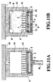
- a relationship between the conventional ink-jet printing head and the recovery cap is downwardly oriented the ink ejection opening forming surface, of the former, and upwardly oriented the recovery cap opposing to the ink ejection opening forming surface. This condition is illustrated in enlarged form in Fig. 11A.
- Fig. 11A is an enlarged section showing an abutting condition of the ink cartridge and the recovery cap in Fig. 10.
- the projecting contours E of the recovery caps abut onto the ink ejection opening forming surface, to define the inside of the projecting contours E as sealed space D for effectively transmitting a suction force F to ink passages 41 and an ink chamber 42.
- Fig. 11B is an enlarged section showing a condition where recovery operation for filling-up ink into the ink chamber and the ink passages from the condition where the ink cartridge and the recovery cap abut.
- suction recovery operation is performed for removing these bubbles by the suction pressure F.
- suction has to be performed by shown acting pressures 01 to 04 in consideration of a damper effect and a meniscus force of bubbles.
- an ejection recovery system for a liquid ejection head including ejection openings for ejecting liquid, liquid passages communicated with the ejection openings, and ejection energy generating elements provided in the liquid passages and generating energy sufficient for ejecting the liquid, comprising:
- a diameter of a cover opening of the cover member is L1 and a length of an array of the ejection openings aligned in a row is L2
- a relationship of L1 ⁇ L2 may be established, and the system further comprises moving means for relatively moving the cover member and the surface including the ejection openings of the liquid ejection head in a direction of length of the array of the ejection openings.
- an ejection recovery system may further comprises ultrasonic wave generating means for applying an ultrasonic wave to the liquid ejection head when vacuum pressure is introduced into the space defined by the cover member and the surface including the ejection openings of the liquid ejection head by the suction means.
- ultrasonic wave generating means By providing the ultrasonic wave generating means, it becomes possible to grow bubbles into greater size and make bubbles to be easily released from walls of the liquid passages and the liquid chamber.
- the liquid ejection head may be placed in an environmental atmosphere at a temperature in a range of about 35 °C to 80 °C, when vacuum pressure is introduced into the space defined by the cover member and the surface including the ejection openings of the liquid ejection head by the suction means.
- a temperature in a range of about 35 °C to 80 °C, when vacuum pressure is introduced into the space defined by the cover member and the surface including the ejection openings of the liquid ejection head by the suction means.
- the ejection recovery system may further comprise an energy generating element for temperature adjustment provided in the liquid passage of the liquid ejection head for adjusting the liquid at a predetermined temperature, and a temperature of the liquid ejection head is adjusted in a range of about 35 °C to 60 °C by driving the temperature adjusting energy generating element, when vacuum pressure is introduced into the space defined by the cover member and the surface including the ejection openings of the liquid ejection head by the suction means.
- an energy generating element for temperature adjustment provided in the liquid passage of the liquid ejection head for adjusting the liquid at a predetermined temperature
- a temperature of the liquid ejection head is adjusted in a range of about 35 °C to 60 °C by driving the temperature adjusting energy generating element, when vacuum pressure is introduced into the space defined by the cover member and the surface including the ejection openings of the liquid ejection head by the suction means.
- the cover member may have flexibility.
- a material of the cover member is selected among Si type rubber and Bu type rubber.
- rubber material containing Si is included in the Si type rubber and rubber material containing butyl group is included in Bu type rubber.
- the ejection recovery system may further comprise monitoring means for optically monitoring a condition of the liquid passage and a liquid chamber communicated with the liquid passage in the liquid ejection head, and suction by the suction means may be performed again when the liquid passage and the liquid chamber in the liquid ejection head as monitored by the monitoring means are not filled with the liquid.
- monitoring means for optically monitoring a condition of the liquid passage and a liquid chamber communicated with the liquid passage in the liquid ejection head, and suction by the suction means may be performed again when the liquid passage and the liquid chamber in the liquid ejection head as monitored by the monitoring means are not filled with the liquid.
- the ejection energy generating means may be a thermal energy generating element generating a thermal energy sufficient for ejecting the liquid.
- the temperature adjusting energy generating element may be a thermal energy generating element for generating a thermal energy sufficient for heating the liquid.
- the cover member contacting with a surface including the ejection openings of the liquid ejection head arranged for orienting the surface including the ejection openings upwardly and suction means for introducing a vacuum pressure into a space defined by the cover member and the surface including the ejection openings, the vacuum pressure is introduced into the space in a condition where bubbles presenting in the liquid passages are floating up toward the ejection openings to effectively discharge bubbles toward the clearance.
- a sectional area of a cover opening of the cover member is S1 and summation of areas of the ejection openings covered by the cover opening is S2, a relationship 10,000 ⁇ S1/S2 ⁇ 10 is satisfied.
- a diameter of the cover opening of the cover member is L1 and a length of the array of the ejection openings aligned in a row is L2, a relationship 1 ⁇ L2/L1 ⁇ 500 is satisfied.
- an ejection recovery method for a liquid ejection head including ejection openings for ejecting liquid, liquid passages communicated with the ejection openings, and ejection energy generating elements provided in the liquid passages and generating energy sufficient for ejecting the liquid, comprising the steps of:
- the method further may comprise a step of relatively moving the cover member and the surface including the ejection openings of the liquid ejection head in a direction of length of the array of the ejection openings.
- the method may further comprise a step of applying an ultrasonic wave to the liquid ejection head when vacuum pressure is introduced into the space defined by the cover member and the surface including the ejection openings of the liquid ejection head.
- the method may further comprise a step of placing the liquid ejection head in an environmental atmosphere at a temperature in a range of about 35 °C to 80 °C, when vacuum pressure is introduced into the space defined by the cover member and the surface including the ejection openings of the liquid ejection head.
- the method may further comprises a step of driving an energy generating element for temperature adjustment provided in the liquid passage for adjusting a temperature of the liquid ejection head in a range of about 35 °C to 60 °C, when vacuum pressure is introduced into the space defined by the cover member and the surface including the ejection openings of the liquid ejection head by the suction means.
- the method may further comprise a step of optically monitoring a condition of the liquid passage and a liquid chamber communicated with the liquid passage in the liquid ejection head, and performing suction again when the liquid passage and the liquid chamber in the liquid ejection head as monitored are not filled with the liquid.
- a liquid ejection printing apparatus performing printing by ejecting liquid to a printing medium from a liquid ejection head including ejection openings ejecting liquid, liquid passages communicated with the ejection openings and ejection energy generating elements provided in the liquid passages and generating energy sufficient for ejecting the liquid, comprising:
- a diameter of a cover opening of the cover member is L1 and a length of an array of the ejection openings aligned in a row is L2
- a relationship of L1 ⁇ L2 may be established, and the system further comprises moving means for relatively moving the cover member and the surface including the ejection openings of the liquid ejection head in a direction of length of the array of the ejection openings.
- an ejection recovery system may further comprises ultrasonic wave generating means for applying an ultrasonic wave to the liquid ejection head when vacuum pressure is introduced into the space defined by the cover member and the surface including the ejection openings of the liquid ejection head by the suction means.
- the liquid ejection head may be placed in an environmental atmosphere at a temperature in a range of about 35 °C to 80 °C, when vacuum pressure is introduced into the space defined by the cover member and the surface including the ejection openings of the liquid ejection head by the suction means.
- the ejection recovery system may further comprise an energy generating element for temperature adjustment provided in the liquid passage of the liquid ejection head for adjusting the liquid at a predetermined temperature, and a temperature of the liquid ejection head is adjusted in a range of about 35 °C to 60 °C by driving the temperature adjusting energy generating element, when vacuum pressure is introduced into the space defined by the cover member and the surface including the ejection openings of the liquid ejection head by the suction means.
- an energy generating element for temperature adjustment provided in the liquid passage of the liquid ejection head for adjusting the liquid at a predetermined temperature
- a temperature of the liquid ejection head is adjusted in a range of about 35 °C to 60 °C by driving the temperature adjusting energy generating element, when vacuum pressure is introduced into the space defined by the cover member and the surface including the ejection openings of the liquid ejection head by the suction means.
- the internal diameter of the suction hole of the elastic member smaller than the length of the ejection opening array, a part of the ejection opening array can be concentrically sucked to omit suction operation for the ejection openings which do not require recovery.
- the ejection recovery system according to the present invention is applicable not only for pre-factory shipment process, such as aging processing or shipping inspection printing, but also as the ejection recovery system to be mounted in a plotter, a large size printer or the like which has smaller constraint in a size of a main body to prevent user from draining unnecessarily a large amount of the ink and thus to contribute for ecology.
- a liquid in the present invention includes an ink which is not in liquid state under a normal temperature and becomes liquid state as heated, in addition to a liquid state ink containing a pigment or the like.
- ink the foregoing liquid will be referred to as ink for the purpose of disclosure.
- the term "recovery” is used in the meaning of not only filling ink (liquid) into ink passages or the like before shipping, but also “recovering” at the time when the ink-jet printing head is loaded on a printer or the like.
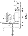
- Fig. 1 is a general front elevation showing one embodiment of an ejection recovery system according to the present invention.
- Figs. 2A and 2B show a construction of an elastic member to be employed in the ejection recovery system shown in Fig. 1, wherein Fig. 2A is a plan view and Fig. 2B is a longitudinal section take along line IIB - IIB of Fig. 2A.
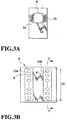
- Figs. 3A and 3B show an ink-jet printing head in an ink cartridge which is effected recovery operation by the ejection recovery system shown in Fig. 1, wherein Fig. 3A is a plan view showing an ink ejection opening forming surface and Fig. 3B shows a plan view showing the ink ejection opening forming surface in enlarged form.
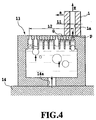
- Fig. 4 is a section showing a condition of ejection recovery operation using the elastic member for the ink-jet printing head in a longitudinal section taken along line IV - IV of Fig. 3B. It should be noted that a power source, a personal computer, a driver, a stage control board necessary for forming the shown embodiment are omitted for clarity.
- reference numeral 1 denotes a hollow cylindrical cover member (cap or elastic member) formed of a rubbery flexible material, such as silicone rubber or butyl rubber.
- a cover opening (suction hole) 1a having an internal diameter L1 is formed within the elastic member 1.
- the elastic member 1 is fixed to an elastic member fixing block 3 at an upper end thereof.
- the suction hole 1a of the elastic member 1 is connected to a suction pump P forming a part of suction means, via a passage formed in the elastic member fixing block 3 and a tube 2 communicated with the passage in the elastic member fixing block 3.
- a length of the elastic member 1 in a longitudinal direction is determined at a length permitting fixing by the elastic member fixing block 3 of Fig. 1, and permitting deflection without causing damage on a ink ejection opening forming surface A, upon movement along an ink ejection opening array direction with contacting on the ink ejection opening forming surface A.
- the elastic member fixing block 3 is fixed on an X stage 4 which is reciprocally movable in directions of arrow a.
- the X stage 4 is fixed on an arm 5a of a Z stage 5 which is reciprocally movable in directions of arrow b.
- the Z stage 5 is fixed at a side of a stage fixing plate 7 installed vertically on a base 6.
- a positioning member 9 for positioning an ink-jet cartridge 8 which will be explained later and is subject to an ejection recovery operation by suction means generally constructed with the elastic member 1, the tube 2 and the suction pump P, is provided.
- loading means 10 arranged on an extension in the direction of arrow a together with the positioning member 9 for securing the ink-jet cartridge 8 positioned by the positioning member 9.
- the loading means 10 is generally constructed with a holding member 11 pushing a side wall portion of the ink-jet cartridge 8 and an air cylinder 12 driving the holding member 11 back and forth in the direction of arrow a.
- a depressing surface member 11a formed of an elastic member is provided for preventing the side wall portion of the ink-jet cartridge 8 from causing deformation or so on due to depression.
- the lower end portion of the elastic member 1 which is movable in X direction (direction of arrow a) and Z direction (direction of arrow b) contacts with the ink ejection opening forming surface A, shown in Figs. 3A and 3B and is movable along the ink ejection opening forming surface A.
- the ink ejection opening forming surface A in the shown embodiment has two rows of ink ejection opening arrays 13a and 13b. In both ink ejection opening arrays, a plurality of ink ejection openings G are formed in the same pitch. A plurality of ink ejection openings G in one of the ink ejection opening arrays are offset in a direction along the ink ejection opening array for a half pitch relative to a plurality of ink ejection openings G in the other ink ejection opening array, and arrangement density of the ejection openings is set to be double of number of the ink ejection openings of the ink ejection opening array on one side.
- Lengths of both ink ejection opening arrays are set at L2 which is greater than a diameter L1 of the suction hole 1a of the elastic member 1.
- These ink ejection opening arrays 13a and 13b are extended in the direction of arrow a of Figs. 1 and 4.
- the ink-jet cartridge 8 is mounted on the upper surface of the base 6 and abuts onto the positioning member 9 to position the ink-jet printing head 13 below the elastic member 1 with orienting the ink ejection opening forming surface A upwardly.
- the holding member 11 is pushed out to fix the ink-jet cartridge 8 on the upper surface of the base 6 by pushing the side wall portion of the positioned ink-jet cartridge 8.
- the lower end portion of the elastic member 1 is abutted onto the end portions of the ink ejection opening arrays 13a and 13b of the ink ejection opening forming surface A of the ink-jet printing head 13, as shown in Fig. 4. Subsequently, by driving the X stage 4 to move in X direction (direction of arrow a), the lower end portion of the elastic member 1 is sequentially abut onto the ink ejection openings aligned in a row.
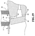
- a recessed portion 50 having a maximum depth T and being arranged ink ejection openings G aligned in a row in the center thereof is continuously formed along the ink ejection opening array.
- a width of the recessed portion 50 is slightly greater than a diameter of the elastic member 1. In practice, the lower end of the elastic member 1 rubbingly moves in contact with the recessed portion 50.
- reference numeral 43 denotes a substrate
- 44 denotes a heater as an ejection energy generating element.
- a magnitude of deflection of the elastic member 1 is maintained substantially as is.
- a small clearance is formed between the suction hole 1a of the elastic member 1 and the ink ejection opening forming surface A (bottom surface of the recessed portion 50).
- this clearance is not so large as causing adverse effect for suction operation through the ink ejection openings G. Rather, the clearance may serve for assisting smooth movement of the elastic member 1.
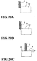
- the three hundreds ten ink ejection openings G are arranged per ink ejection opening array at a pitch of 40 ⁇ m. Accordingly, the length L2 of the ink ejection opening array is 12.4 mm. Preferred diameter of the suction hole 1a of the elastic member 1 is 1 mm. Therefore, in the condition shown in Fig. 18B, while number of ink ejection openings simultaneously mating with the suction hole 1a of the elastic member 1 is conceptually shown, twenty-five ink ejection openings should mate simultaneously with the suction hole 1a in practice. Assuming that relative motion speed of the elastic member 1 is set at 4 mm/sec, for example, necessary period for suction recovery operation for all of the ink ejection openings would be approximately 4 seconds.
- the relationship between effective sectional area of the suction hole 1a of the elastic member 1 and total sectional area of the ink ejection openings to be simultaneously included in the effective sectional area of the suction hole 1a is preferred to satisfy the following expression, assuming that the sectional area of the suction hole 1a of the elastic member 1 is S1 and the summation of the area of the ink ejection openings G covered with the suction hole 1a is S2: 10,000 ⁇ S1/S2 ⁇ 10
- S1/S2 is less than or equal to 10,000 in view of efficiency of sucking and S1/S2 is more than or equal to 10 in view of assurance of sucking.
- a relationship between the diameter of the suction hole 1a of the elastic member 1 and the length of the ink ejection opening array is preferred to satisfy the following expression, assuming that the diameter of the suction hole 1a of the elastic member 1 is L1 and the length of the array of the ink ejection openings G aligned in a row is L2: 1 ⁇ L2/L1 ⁇ 500
- L2/L1 is more than 1 in view of assurance of sucking and L2/L1 is less than or equal to 500 in view of efficiency of sucking.
- the elastic member 1 may be reciprocated for several times as required.
- the suction pump P forming a part of the foregoing suction means is driven to generate a vacuum pressure (negative or less pressure than atmospheric pressure) introduced into the sealed space defined by the elastic member 1 and the ink ejection opening forming surface A oriented upwardly via the elastic member 1 and the tube 2 or the like, to sequentially suck not only the ink but also bubbles residing in the ink or floating up to the ink ejection opening, from the ink ejection opening G.
- the ink-jet cartridge 8 can be adapted for high speed printing.
- the suction pump P to be used here is preferred to perform recovery operation with maintaining the suction pressure constant. Therefore, as the suction pump P, a tube pump, a gear pump, syringe pump and so on may be used.
- the diameter L1 of the suction hole 1a of the elastic member 1 is set to be smaller than the length L2 of the ink ejection opening array, only ink ejection openings at necessary portion can be concentrically sucked to prevent loss of suction pressure H as shown in Fig. 4.
- As a result of low suction pressure loss by concentric suction it becomes not extremely necessary to achieve high fitting ability between the ink ejection opening forming surface and the elastic member which is inherent conventionally.
- slight leakage between the ink ejection opening forming surface and the elastic member is permitted.
- the diameter L1 of the suction hole 1a of the elastic member 1 is shorter than the length L2 of the ink ejection opening array, even if bubble is present, it may not be influenced by all bubbles to permit concentrically apply a force P greater than action pressure N and O1 to O4 to perform effective recovery operation without sucking and draining extra amount of ink.
- a mechanism for applying ultrasonic wave to the ink-jet printing head warming the ink-jet printing head, for example, for expanding bubbles and whereby easily releasing bubbles from the ink passages and the ink chamber.
- bubbles can be effectively moved by placing the overall ejection recovery system in an environmental atmosphere at a temperature in a range of about 35 °C to 80 °C, or setting the temperature of the ink-jet printing head at about 35 °C to 60 °C by driving an energy generating element of the ink-jet printing head for temperature adjustment.
- the wall member of the ink chamber or the like may be formed of a transparent material, and light is irradiated through the wall member to make judgment between the condition where the ink is filled and the condition where the ink is not filled based on difference of light reflection or light absorption.
- the recovery cap sealingly covering all of the ink ejection openings as required conventionally, also becomes quite bulky. Furthermore, high fitting ability between the recovery cap and the ink-jet printing head is required.
- the diameter L1 of the suction hole is shorter than the length L2 of the ink ejection opening array in the present invention, recovery becomes possible without requiring high fitting ability irrespective of number of ink ejection openings by the effective action of the suction pressure. As a result, the ink amount to be sucked and drained can be significantly reduced.
- Fig. 12 is a perspective view showing one embodiment of a large size ink-jet printer, namely a plotter 100, in which the ejection recovery system according to the present invention is built-in.
- the ink-jet printer 100 has a generally rectangular parallelepiped casing 104 supported on stands 102.
- a cover 106 which can be opened and closed, is provided at the center of front portion of the casing 104.
- a guide shaft 108 extending in a lateral direction is provided as is well known in the art so as to guide a carriage 110 reciprocally on which a cartridge 113 including an ink-jet printing head 112 is mounted.
- a central region 104A of the casing 104 is a printing region by the ink-jet printing head 112
- a left side region 104B is a region for receiving the ink-jet printing head 112 when a printing signal is not present, which region 104B includes a home position of the ink-jet printing head 112.
- a right side region 104C is a region to perform recovery of the ink-jet printing head 112 on the basis of a sequence command from a not shown controller or a command selectively input by a user, which region 104C includes a cleaning position.
- a printing medium 114 is ejected from a front face of the plotter 100 through a clearance located at a lower edge portion of the cover 106.
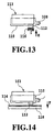
- Fig. 13 is a section taken along line XIII - XIII of Fig. 12 showing a condition where the ink-jet printing head 112 is housed.
- a protection cap 116 is elevated in a direction of arrow E to seal the ink ejection opening forming surface of the ink-jet printing head 112 to prevent evaporation of the ink.
- the ink-jet printing head 112 is fixed on the carriage 110 which is slidably guided by the guide shaft 108. The carriage 110 is locked so as not to move as depressed in the direction of arrow E by the protection cap 116.
- Fig. 14 is a section taken along line XIV - XIV of Fig. 12, showing a condition where the ink-jet printing head 112 is placed in the printing condition.
- the ink-jet printing head 112 forms an image on the printing medium 114 mounted on the platen 118 by ejecting the ink in the direction of arrow F with moving along the guide shaft 108.
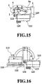
- Fig. 15 is a section taken along line XV - XV of Fig. 12 and showing a condition to perform recovery operation of the ink-jet printing head 112 at the cleaning position for performing recovery operation.
- the carriage 100 is moved from a printing condition where the ink-jet printing head 112 is oriented downwardly to the cleaning position in response to input of a recovery operation signal.
- a carriage reversing mechanism (not shown) which is driven by a motor, is provided to change a direction of the carriage 110 by reversing the carriage 110 over 180° about the guide shaft 108 as shown in Fig. 16 at the cleaning position or before reaching the cleaning position.
- a stopper 120 which is formed of a shock absorbing material, such as a silicon rubber or the like.
- the home position and the cleaning position can be provided on the back side of the printing region instead of left and right sides of the printing region as set forth above. This contributes for down-sizing of the plotter 100 and thus for space saving.
- the elastic member 1 After completing predetermined suction operation, the elastic member 1 is elevated in a direction of arrow J to terminate suction operation. After completion of such suction operation, the carriage reversing operation is operated again to pivot the carriage in a direction of arrow H shown in Fig. 16 to return the ink-jet printing head 112 to the printing position to complete recovery operation.
- the following effect can be obtained by providing the carriage reversing mechanism. Namely, by an impact upon stabilization after pivoting in the direction of arrow G before suction, bubbles adhering on the inner wall or the like of the ink chamber of the ink-jet printing head 112 and residing within the ink chamber is released to flow toward the ink ejection openings which can be easily sucked. Furthermore, by an impact upon stabilization after pivoting in the direction of arrow H after suction recovery, bubbles on the side of the ink ejection openings are moved toward the ink chamber which does not influence for ejection even if any bubbles reside.
- the plotter of the shown embodiment orients the ink ejection openings downwardly which is optimal for ejection in a normal printing state and upwardly which is optimal for suction in recovery operation. Therefore, good recovery condition can be attained.
- the ink ejection openings are oriented upwardly
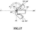
- an example where the orientation of the ink ejection opening forming surface is reversed over 180° is shown in Figs. 15 and 16.
- the pivoting range may be about 135° to 225° as shown in Fig. 17.
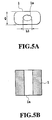
- Figs. 5A and 5B show the embodiment, in which a contact surface of the elastic member 1 mating with the ink ejection opening forming surface is generally rectangular, and the ink suction hole 1a is elliptic.
- an internal diameter L1 of the suction hole 1a is a longer diameter of elliptic, in order to move with abutting onto the ink ejection opening forming surface and sucking the ink without damaging the ink ejection openings, it is preferred to move the elastic member 1 in a direction Q for high deflection ability.
- Figs. 6A and 6B show the embodiment which has the ink suction hole 1a which has a circular contact surface of the elastic member 1 mating with the ink ejection opening forming surface and has an internal diameter L1.
- an annular projection 25 is provided at the tip end of the elastic member 1. The elastic member 1 is moved with sealingly fitting the annular projection 25 onto the ink ejection opening forming surface with sucking the ink. Due to no direction dependency of deflection ability for circular shape of the elastic member 1, there is no restriction in direction of motion, namely in the direction for mounting the elastic member 1 on the system.
- Figs. 7A and 7B show the embodiment, in which a contact surface of the elastic member 1 mating with the ink ejection opening forming surface is generally rectangular, and the ink suction hole 1a is divided into three fractions. It is preferred to move the elastic member 1 in a direction R for high deflection ability. Also, by dividing the ink suction hole 1a into three fractions in a direction perpendicular to motion direction, required precision of contact with the ink ejection opening can be reduced. In this case, number of suction holes consisting the length L1 of the suction hole 1a can be any number. However, it should be considered that when the size of diameter of the suction hole becomes smaller, pressure loss upon suction becomes large.
- Figs. 8A and 8B show the embodiment, in which the contact surface of the elastic member 1 mating with the ink ejection opening forming surface is elliptic, and the ink suction hole is also elliptic.
- an annular projection 26 is provided at the tip end of the elastic member 1. The elastic member 1 is moved with sealingly fitting the annular projection 26 onto the ink ejection opening forming surface with sucking the ink. In order to move with abutting onto the ink ejection opening forming surface and sucking the ink without damaging the ink ejection openings, it is preferred to move the elastic member 1 in a direction S for high deflection ability.
- the inner diameter L1 of the elliptic suction hole 1a is set on the shorter diameter side and the direction perpendicular to the motion direction S is set on the longer diameter side.
- the elastic member to be used in the ejection recovery system is preferred to be a flexible material, such as a silicone type rubber, a butyl type rubber or the like in order to obtain a deflection ability to be satisfactorily fitted onto the ink ejection opening forming surface and to prevent the ink ejection opening forming surface from being damaged.
- the present invention achieves distinct effects when applied to a recording head or a recording apparatus which has means for generating thermal energy such as electrothermal transducers or laser light, and which causes changes in ink by the thermal energy so as to eject ink. This is because such a system can achieve a high density and high resolution recording.
- the on-demand type apparatus has electrothermal transducers, each disposed on a sheet or liquid passage that retains liquid (ink), and operates as follows: first, one or more drive signals are applied to the electrothermal transducers to cause thermal energy corresponding to recording information; second, the thermal energy induces sudden temperature rise that exceeds the nucleate boiling so as to cause the film boiling on heating portions of the recording head; and third, bubbles are grown in the liquid (ink) corresponding to the drive signals. By using the growth and collapse of the bubbles, the ink is expelled from at least one of the ink ejection orifices of the head to form one or more ink drops.
- the drive signal in the form of a pulse is preferable because the growth and collapse of the bubbles can be achieved instantaneously and suitably by this form of drive signal.
- a drive signal in the form of a pulse those described in U.S. patent Nos. 4,463,359 and 4,345,262 are preferable.
- the rate of temperature rise of the heating portions described in U.S. patent No. 4,313,124 be adopted to achieve better recording.
- U.S. patent Nos. 4,558,333 and 4,459,600 disclose the following structure of a recording head, which is incorporated to the present invention: this structure includes heating portions disposed on bent portions in addition to a combination of the ejection orifices, liquid passages and the electrothermal transducers disclosed in the above patents. Moreover, the present invention can be applied to structures disclosed in Japanese Patent Application Laying-open Nos. 59-123670 (1984) and 59-138461 (1984) in order to achieve similar effects.
- the former discloses a structure in which a slit common to all the electrothermal transducers is used as ejection orifices of the electrothermal transducers, and the latter discloses a structure in which openings for absorbing pressure waves caused by thermal energy are formed corresponding to the ejection orifices.
- the present invention can be also applied to a so-called full-line type recording head whose length equals the maximum length across a recording medium.
- a recording head may consists of a plurality of recording heads combined together, or one integrally arranged recording head.
- the present invention can be applied to various serial type recording heads: a recording head fixed to the main assembly of a recording apparatus; a conveniently replaceable chip type recording head which, when loaded on the main assembly of a recording apparatus, is electrically connected to the main assembly, and is supplied with ink therefrom; and a cartridge type recording head integrally including an ink reservoir.
- a recovery system or a preliminary auxiliary system for a recording head as a constituent of the recording apparatus because they serve to make the effect of the present invention more reliable.
- the recovery system are a capping means and a cleaning means for the recording head, and a pressure or suction means for the recording head.
- the preliminary auxiliary system are a preliminary heating means utilizing electrothermal transducers or a combination of other heater elements and the electrothermal transducers, and a means for carrying out preliminary ejection of ink independently of the ejection for recording. These systems are effective for reliable recording.
- the number and type of recording heads to be mounted on a recording apparatus can be also changed. For example, only one recording head corresponding to a single color ink, or a plurality of recording heads corresponding to a plurality of inks different in color or concentration can be used.
- the present invention can be effectively applied to an apparatus having at least one of the monochromatic, multi-color and full-color modes.
- the monochromatic mode performs recording by using only one major color such as black.
- the multi-color mode carries out recording by using different color inks, and the full-color mode performs recording by color mixing.
- inks that are liquid when the recording signal is applied can be used: for example, inks can be employed that solidify at a temperature lower than the room temperature and are softened or liquefied in the room temperature. This is because in the ink jet system, the ink is generally temperature adjusted in a range of 30° C - 70° C so that the viscosity of the ink is maintained at such a value that the ink can be ejected reliably.
- the present invention can be applied to such apparatus where the ink is liquefied just before the ejection by the thermal energy as follows so that the ink is expelled from the orifices in the liquid state, and then begins to solidify on hitting the recording medium, thereby preventing the ink evaporation: the ink is transformed from solid to liquid state by positively utilizing the thermal energy which would otherwise cause the temperature rise; or the ink, which is dry when left in air, is liquefied in response to the thermal energy of the recording signal.
- the ink may be retained in recesses or through holes formed in a porous sheet as liquid or solid substances so that the ink faces the electrothermal transducers as described in Japanese Patent Application Laying-open Nos. 54-56847 (1979) or 60-71260 (1985).
- the present invention is most effective when it uses the film boiling phenomenon to expel the ink.
- the ink jet recording apparatus of the present invention can be employed not only as an image output terminal of an information processing device such as a computer, but also as an output device of a copying machine including a reader, and as an output device of a facsimile apparatus having a transmission and receiving function.
- An ink-jet cartridge (8) constructed with an ink-jet printing head (13) and an ink tank (14) is positioned and filed on an upper surface of a base (6) in a condition where ink ejection opening forming surface (A) of the head (13) is oriented upwardly.
- the ink ejection opening forming surface (A) is contacted with a lower end portion of an elastic member (1) which is movable in a direction of arrow a or arrow b.
- suction hole (1a) or the like of the elastic member (1) vacuum pressure is introduced into a space between the elastic member (1) and the ink ejection opening forming surface (A) to discharge bubbles residing in liquid passages or floating up to the ink ejection openings.
Landscapes
- Ink Jet (AREA)
Applications Claiming Priority (2)
| Application Number | Priority Date | Filing Date | Title |
|---|---|---|---|
| JP21944998 | 1998-08-03 | ||
| JP21944998 | 1998-08-03 |
Publications (2)
| Publication Number | Publication Date |
|---|---|
| EP0978382A2 true EP0978382A2 (de) | 2000-02-09 |
| EP0978382A3 EP0978382A3 (de) | 2000-07-19 |
Family
ID=16735601
Family Applications (1)
| Application Number | Title | Priority Date | Filing Date |
|---|---|---|---|
| EP99115227A Withdrawn EP0978382A3 (de) | 1998-08-03 | 1999-08-02 | Ausstosswiederherstellungssystem und Verfahren |
Country Status (2)
| Country | Link |
|---|---|
| US (1) | US6543876B2 (de) |
| EP (1) | EP0978382A3 (de) |
Cited By (1)
| Publication number | Priority date | Publication date | Assignee | Title |
|---|---|---|---|---|
| EP1980402A1 (de) | 2002-04-25 | 2008-10-15 | Brother Kogyo Kabushiki Kaisha | Tintenstrahlkopf und Tintenstrahldrucker |
Families Citing this family (11)
| Publication number | Priority date | Publication date | Assignee | Title |
|---|---|---|---|---|
| US6715855B2 (en) * | 2001-05-23 | 2004-04-06 | Fuji Xerox Co., Ltd. | Ink jet recording device and bubble removing method |
| JP4261983B2 (ja) * | 2003-05-22 | 2009-05-13 | キヤノン株式会社 | インクタンク |
| US20050225592A1 (en) * | 2004-04-07 | 2005-10-13 | Stratitec Inc. | Inkjet cartridge cleaning devices |
| US20050264600A1 (en) * | 2004-05-27 | 2005-12-01 | Hewlett-Packard Development Company, L.P. | Emission of fluid droplet from printhead with coherent irradiation |
| JP2007098805A (ja) * | 2005-10-05 | 2007-04-19 | Fujifilm Corp | 液体吐出装置および液体メンテナンス方法 |
| JP2008207452A (ja) * | 2007-02-27 | 2008-09-11 | Ricoh Co Ltd | 画像形成装置 |
| JP5076798B2 (ja) * | 2007-10-15 | 2012-11-21 | ブラザー工業株式会社 | インク容器 |
| JP4687927B2 (ja) * | 2008-07-25 | 2011-05-25 | ブラザー工業株式会社 | 液滴吐出装置 |
| JP5590852B2 (ja) * | 2008-12-17 | 2014-09-17 | キヤノン株式会社 | 液体吐出ヘッドカートリッジの液体充填方法、製造方法および製造装置 |
| ITVI20120278A1 (it) | 2012-10-22 | 2014-04-23 | New System Srl | Gruppo di stampa del tipo perfezionato e dispositivo di stampa a getto d'inchiostro comprendente il suddetto gruppo di stampa |
| US11801370B2 (en) | 2021-02-17 | 2023-10-31 | Funai Electric Co., Ltd. | Gas management for jetting cartridge |
Family Cites Families (30)
| Publication number | Priority date | Publication date | Assignee | Title |
|---|---|---|---|---|
| CA1127227A (en) | 1977-10-03 | 1982-07-06 | Ichiro Endo | Liquid jet recording process and apparatus therefor |
| JPS5936879B2 (ja) | 1977-10-14 | 1984-09-06 | キヤノン株式会社 | 熱転写記録用媒体 |
| JPS5517571A (en) * | 1978-07-26 | 1980-02-07 | Seiko Epson Corp | Ink injection device |
| US4330787A (en) | 1978-10-31 | 1982-05-18 | Canon Kabushiki Kaisha | Liquid jet recording device |
| US4345262A (en) | 1979-02-19 | 1982-08-17 | Canon Kabushiki Kaisha | Ink jet recording method |
| US4463359A (en) | 1979-04-02 | 1984-07-31 | Canon Kabushiki Kaisha | Droplet generating method and apparatus thereof |
| US4313124A (en) | 1979-05-18 | 1982-01-26 | Canon Kabushiki Kaisha | Liquid jet recording process and liquid jet recording head |
| JPS5642661A (en) * | 1979-09-17 | 1981-04-20 | Ricoh Co Ltd | Ink jet printing device |
| US4558333A (en) | 1981-07-09 | 1985-12-10 | Canon Kabushiki Kaisha | Liquid jet recording head |
| JPS58101066A (ja) * | 1981-12-09 | 1983-06-16 | Konishiroku Photo Ind Co Ltd | インクジエツト記録装置 |
| DE3247540A1 (de) * | 1981-12-26 | 1983-07-07 | Konishiroku Photo Industry Co., Ltd., Tokyo | Tintenstrahlschreiber |
| JPS59123670A (ja) | 1982-12-28 | 1984-07-17 | Canon Inc | インクジエツトヘツド |
| JPS59138461A (ja) | 1983-01-28 | 1984-08-08 | Canon Inc | 液体噴射記録装置 |
| JPS6071260A (ja) | 1983-09-28 | 1985-04-23 | Erumu:Kk | 記録装置 |
| US4600928A (en) * | 1985-04-12 | 1986-07-15 | Eastman Kodak Company | Ink jet printing apparatus having ultrasonic print head cleaning system |
| JPS62113555A (ja) * | 1985-11-13 | 1987-05-25 | Canon Inc | インクジエツト記録装置 |
| JP2718724B2 (ja) * | 1987-11-27 | 1998-02-25 | キヤノン株式会社 | インクジェット記録装置、該装置用キャップユニットおよびインクジェットヘッドの回復方法 |
| EP0610959B1 (de) * | 1989-11-22 | 1997-07-23 | Canon Kabushiki Kaisha | Farbstrahlaufzeichnungsvorrichtung |
| EP0445526B1 (de) * | 1990-02-02 | 1995-05-24 | Canon Kabushiki Kaisha | Tintenstrahl-Aufzeichnungsgerät |
| DE69219180T2 (de) * | 1991-02-12 | 1997-10-02 | Canon Kk | Tintenstrahlaufzeichnungssystem und Verfahren |
| JP3161050B2 (ja) | 1991-06-12 | 2001-04-25 | 富士ゼロックス株式会社 | インクジェットヘッドのメンテナンス装置 |
| EP0540344B1 (de) * | 1991-10-31 | 1999-01-20 | Canon Kabushiki Kaisha | Rückgewinnungsvorrichtung und Tintenstrahlaufzeichnungsgerät mit einer solchen Rückgewinnungsvorrichtung |
| US5376958A (en) * | 1992-05-01 | 1994-12-27 | Hewlett-Packard Company | Staggered pens in color thermal ink-jet printer |
| JPH06134998A (ja) * | 1992-10-22 | 1994-05-17 | Canon Inc | インクジェット記録装置 |
| JPH06320744A (ja) * | 1993-04-19 | 1994-11-22 | Xerox Corp | 全巾インクジェットプリンタ用の湿式拭い保守装置 |
| EP0661162B1 (de) * | 1993-12-28 | 2000-07-12 | Canon Kabushiki Kaisha | Substrat für einen Tintenstrahlkopf, Tintenstrahlkopf und Tintenstrahlgerät |
| JP3417089B2 (ja) * | 1994-09-28 | 2003-06-16 | 村田機械株式会社 | インクジェットプリンタ |
| US6095633A (en) * | 1994-10-06 | 2000-08-01 | Lexmark International, Inc. | Process for priming a multi-chamber ink jet print head |
| US5574485A (en) * | 1994-10-13 | 1996-11-12 | Xerox Corporation | Ultrasonic liquid wiper for ink jet printhead maintenance |
| JP3368147B2 (ja) * | 1996-07-04 | 2003-01-20 | キヤノン株式会社 | プリントヘッドおよびプリント装置 |
-
1999
- 1999-08-02 EP EP99115227A patent/EP0978382A3/de not_active Withdrawn
- 1999-08-03 US US09/365,901 patent/US6543876B2/en not_active Expired - Lifetime
Cited By (2)
| Publication number | Priority date | Publication date | Assignee | Title |
|---|---|---|---|---|
| EP1980402A1 (de) | 2002-04-25 | 2008-10-15 | Brother Kogyo Kabushiki Kaisha | Tintenstrahlkopf und Tintenstrahldrucker |
| EP1980402B1 (de) * | 2002-04-25 | 2009-12-30 | Brother Kogyo Kabushiki Kaisha | Tintenstrahlkopf und Tintenstrahldrucker |
Also Published As
| Publication number | Publication date |
|---|---|
| US20030007029A1 (en) | 2003-01-09 |
| EP0978382A3 (de) | 2000-07-19 |
| US6543876B2 (en) | 2003-04-08 |
Similar Documents
| Publication | Publication Date | Title |
|---|---|---|
| US6557989B1 (en) | Print head and ink jet printing apparatus | |
| US5648802A (en) | Cap for an ink jet recording head | |
| JPH0373354A (ja) | インクジェット記録装置の回復方法 | |
| JPH0373352A (ja) | インクジェット記録装置 | |
| US6543876B2 (en) | Ejection recovery system and ejection recovery method | |
| EP0631872B1 (de) | Tintenstrahlkopf, Tintenstrahlgerät und Verfahren zur Durchführung einer Rückgewinnungsoperation des Gerätes | |
| CA2040120C (en) | Discharge recovery method for an ink jet recording head and device for carrying out the same | |
| EP1190860B1 (de) | Tintenstrahldruckgerät, Tintenversorgungsverfahren und Verfahren zur Wiederherstellung des Tintenstrahldruckkopfes | |
| US6022092A (en) | Ink jet recording apparatus with means for equalizing ink droplet volumes | |
| US5483266A (en) | Ink jet recording apparatus with two storage modes | |
| JPH0747679A (ja) | インクジェット記録装置 | |
| US6145956A (en) | Discharge recovery method and apparatus for an ink jet recording head | |
| JPH10211720A (ja) | インクジェット記録装置および吐出回復処理方法 | |
| JPH11334092A (ja) | インクジェット記録装置 | |
| JP3234087B2 (ja) | インクジェット記録装置 | |
| JP2000108383A (ja) | 吐出回復装置および吐出回復方法 | |
| JP3113123B2 (ja) | インクジェット記録装置 | |
| JPH07205438A (ja) | インクジェット記録装置 | |
| JP3188557B2 (ja) | インクジェット記録装置 | |
| JP3248544B2 (ja) | インクジェット記録装置 | |
| US8282186B2 (en) | Liquid ejection method for ejecting an ink containing a color material and an improvement liquid | |
| JPH07290716A (ja) | インクジェット記録装置 | |
| JP3014270B2 (ja) | インクジェット記録装置 | |
| JP2000015832A (ja) | インクジェット記録装置 | |
| JP2773969B2 (ja) | インクジェット記録装置および該装置用吐出回復装置 |
Legal Events
| Date | Code | Title | Description |
|---|---|---|---|
| PUAI | Public reference made under article 153(3) epc to a published international application that has entered the european phase |
Free format text: ORIGINAL CODE: 0009012 |
|
| AK | Designated contracting states |
Kind code of ref document: A2 Designated state(s): DE ES FR GB IT NL |
|
| AX | Request for extension of the european patent |
Free format text: AL;LT;LV;MK;RO;SI |
|
| PUAL | Search report despatched |
Free format text: ORIGINAL CODE: 0009013 |
|
| AK | Designated contracting states |
Kind code of ref document: A3 Designated state(s): AT BE CH CY DE DK ES FI FR GB GR IE IT LI LU MC NL PT SE |
|
| AX | Request for extension of the european patent |
Free format text: AL;LT;LV;MK;RO;SI |
|
| RIC1 | Information provided on ipc code assigned before grant |
Free format text: 7B 41J 2/165 A, 7B 41J 25/316 B, 7B 41J 2/19 B |
|
| 17P | Request for examination filed |
Effective date: 20001201 |
|
| AKX | Designation fees paid |
Free format text: DE ES FR GB IT NL |
|
| 17Q | First examination report despatched |
Effective date: 20080205 |
|
| STAA | Information on the status of an ep patent application or granted ep patent |
Free format text: STATUS: THE APPLICATION HAS BEEN WITHDRAWN |
|
| 18W | Application withdrawn |
Effective date: 20080801 |