EP0978400A2 - Fahrzeugdach - Google Patents
Fahrzeugdach Download PDFInfo
- Publication number
- EP0978400A2 EP0978400A2 EP99115388A EP99115388A EP0978400A2 EP 0978400 A2 EP0978400 A2 EP 0978400A2 EP 99115388 A EP99115388 A EP 99115388A EP 99115388 A EP99115388 A EP 99115388A EP 0978400 A2 EP0978400 A2 EP 0978400A2
- Authority
- EP
- European Patent Office
- Prior art keywords
- locking
- coupling
- roof
- control part
- vehicle roof
- Prior art date
- Legal status (The legal status is an assumption and is not a legal conclusion. Google has not performed a legal analysis and makes no representation as to the accuracy of the status listed.)
- Granted
Links
- 230000008878 coupling Effects 0.000 claims abstract description 88
- 238000010168 coupling process Methods 0.000 claims abstract description 88
- 238000005859 coupling reaction Methods 0.000 claims abstract description 88
- 238000006073 displacement reaction Methods 0.000 claims description 18
- 241000446313 Lamella Species 0.000 description 26
- 239000002131 composite material Substances 0.000 description 10
- 238000000034 method Methods 0.000 description 8
- 230000008569 process Effects 0.000 description 8
- 230000007246 mechanism Effects 0.000 description 5
- 238000007789 sealing Methods 0.000 description 4
- 101100390736 Danio rerio fign gene Proteins 0.000 description 2
- 101100390738 Mus musculus Fign gene Proteins 0.000 description 2
- 230000005540 biological transmission Effects 0.000 description 2
- 230000009467 reduction Effects 0.000 description 2
- MYVIATVLJGTBFV-UHFFFAOYSA-M thiamine(1+) chloride Chemical compound [Cl-].CC1=C(CCO)SC=[N+]1CC1=CN=C(C)N=C1N MYVIATVLJGTBFV-UHFFFAOYSA-M 0.000 description 2
- 238000009423 ventilation Methods 0.000 description 2
- 230000001133 acceleration Effects 0.000 description 1
- 230000008859 change Effects 0.000 description 1
- 239000013013 elastic material Substances 0.000 description 1
- 230000001902 propagating effect Effects 0.000 description 1
- 230000035939 shock Effects 0.000 description 1
- 230000001360 synchronised effect Effects 0.000 description 1
- 230000007306 turnover Effects 0.000 description 1
- 230000003313 weakening effect Effects 0.000 description 1
Images





Classifications
-
- B—PERFORMING OPERATIONS; TRANSPORTING
- B60—VEHICLES IN GENERAL
- B60J—WINDOWS, WINDSCREENS, NON-FIXED ROOFS, DOORS, OR SIMILAR DEVICES FOR VEHICLES; REMOVABLE EXTERNAL PROTECTIVE COVERINGS SPECIALLY ADAPTED FOR VEHICLES
- B60J7/00—Non-fixed roofs; Roofs with movable panels, e.g. rotary sunroofs
- B60J7/02—Non-fixed roofs; Roofs with movable panels, e.g. rotary sunroofs of sliding type, e.g. comprising guide shoes
- B60J7/04—Non-fixed roofs; Roofs with movable panels, e.g. rotary sunroofs of sliding type, e.g. comprising guide shoes with rigid plate-like element or elements, e.g. open roofs with harmonica-type folding rigid panels
- B60J7/047—Non-fixed roofs; Roofs with movable panels, e.g. rotary sunroofs of sliding type, e.g. comprising guide shoes with rigid plate-like element or elements, e.g. open roofs with harmonica-type folding rigid panels movable to overlapping or nested relationship
Definitions
- the invention relates to a vehicle roof according to the preamble of claim 1.
- Such a generic vehicle roof is known from DE 195 29 522 C1 or DE 195 29 702 C1 known.
- Inside is a locking mechanism with one described pivoting bolt, which adjacent fasteners under the direct influence of the opening movement of these two fasteners previous fastener, i.e. without the use of a bolt slide locked together as soon as these two fasteners are fully swung out, or unlocked again under the influence of the corresponding closing movement.
- a disadvantage of this locking mechanism is that in an accident the entire acceleration of the Plate pack from the lock between the last two fasteners must be caught, which can lead to failure of the lock.
- This task is based on a vehicle roof of the type mentioned solved according to the invention in that at least a part of all fully pivoted Fasteners are in fixed engagement with a common coupling element, which can be moved along the roof-mounted guideway or can be fixed with respect to this
- the coupling element in at least one position can be locked with the roof-mounted guideway, wherein preferably also one from a drive for displacement along the guideway driven coupling control part is provided, which can be locked with the coupling element is. This contributes to accident safety.
- the coupling element has a Locking device for locking with the roof-mounted guideway or with the Coupling control part, which is caused by a displacement of the coupling control part with respect to the Coupling element is actuated in the closed position of the cover element assembly so that it the lock with the roof-mounted guideway releases and the lock with the Coupling control part closes.
- the coupling control part is preferably in such a manner with the rearmost fastening element Intervention that a displacement of the coupling control part along the roof-mounted guideway swings out or swings back the rearmost fastener. This saves the need to actuate the rearmost fastener by one arranged front drive, so that no power transmission device from the front end of the Roof opening to the rear end is required.
- the coupling element further comprises a plurality of links which are pivotable with one another are connected. This allows the coupling element to be adapted to curved roof shapes.
- the locking between the fastening elements and the expediently takes place Coupling element via a locking element which is designed as a rocker switch, which in its middle section is pivotally mounted, at one end section a locking part and has an actuating arm at its other end section, the coupling element for each fastening element has a locking recess for receiving the locking part.
- lamella is not intended to limit the geometric shape, in particular with regard to the ratio of length to width. It can are also cover elements which are, for example, about as long as they are wide.
- the vehicle roof 9 which is explained here and which is to be referred to as a lamella roof, shows how 1 and 2, a sequence of sliding lamellae 10a up to 10d. These slats are used for optional locking or at least partially Uncovering a roof opening 13 in a fixed roof surface 11 of a motor vehicle 12 is trained.
- the slats 10a to 10d shift, the one with the double arrow 14 in the exemplary embodiment shown indicated displacement direction runs parallel to the longitudinal axis of the vehicle.
- the closed position of the lamellae 10a to 10d cross with their direction of displacement running longitudinal edges or sealing elements arranged there sealing to each other. They form a flat lamella composite, as shown in Fig. 1 for the two slats 10d and 10c is indicated.
- the slats 10a to 10d can also each about a (virtual) swivel axis extending transversely to the direction of displacement arrow 14 are pivoted, approximately in height in the illustrated embodiment the fixed roof surface 11.
- An adjustment mechanism explained in more detail below coordinates the displacement and Pivotal movements of the individual slats 10a to 10d such that when adjusting the Sliding lamellae the flat lamella composite a translational movement in the Movement direction (arrow 14) and this composite when opening the roof 9 in Area of the front and / or the rear composite end by moving out each a lamella from the lamella composite lamella or when closing the Roof is restored.
- the lamella 10a can then start in the above-described inclined position together with the remaining, remaining in the flat lamella composite, i.e. Not swung out, slats 10b to 10d to be moved to the rear.
- the Lamella 10a continuously pivoted into its end position. After the lamella 10a their in the FiGn. 1 and 2 illustrated rear end position is reached, the next Slat 10b issued. This game repeats itself until all according to FIG. 2 Sliding slats 10a to 10c are issued and pushed back into their open position.
- the roof 9 is closed, starting from the open position in accordance with FIG Fig.
- Another alternative is to adjust the slat assembly from the front and is applied from behind, so that a package according to FIG. 4 in the open state issued and pushed together slats 10a to 10d in a central part of the Longitudinal dimension of the roof opening 13 is also available as a package with a variable package size any place of the roof opening can be moved.
- the roof takes one Ventilation position on, which is also used when the slats are in the closed position when it is raining can be.
- the wind deflector 16 lays down with its in the closed position of the roof 9 Rear edge against the front edge of the sliding slat in the front end position 10d sealing. It closes the foremost part of the roof opening 13.
- the design can also be made so that the flat composite of Slats 10a to 10d in the closed position from the front edge to the rear edge of the Roof opening 13 is sufficient and thus only takes over the locking function.
- a wind deflector is provided in a manner known per se for sunroofs be that disappears under the fixed roof surface when the roof is closed and that automatically changes to a working position when the roof is opened.
- the FiGn. 1 and 2 shows a vehicle roof with four sliding slats 10a to 10d. It goes without saying however, that the number of sliding slats is basically arbitrary depending on the respective circumstances can be selected.
- the entire roof opening 13 can for example, be covered by only two slats or cover elements.
- Each lamella 10a to 10d is on its two narrow sides with one fastening element each 20a to 20d connected.
- the fastening elements 20a to 20d are preferably in the are known from DE 196 08 916 Cl and are therefore no longer used here fully describe in detail.
- a fastening element 20 consists of an outside lying adjustment element 60 and an inside, carrying a lamella 10 Carrier element (not shown) together.
- the adjusting elements 60 each have one rear part 21 and a front part 28.
- a curved, rear-facing Contact surface 25 formed, which is bounded at the bottom by an edge 64.
- the bottom 22 of the rear part 21 is of a slightly curved surface in the displacement direction 14 educated.
- a curved slotted slot 42 is formed, the curvature of which is approximately that Curvature of the bottom 22 runs parallel and its front end with 49 and its rear end are designated 48.
- the inside of the rear part 21 is 26 designated.
- the fastening element 20 is in a known manner in a roof-mounted guideway, which in a guide rail 75 is formed, guided.
- a driver 23 with one to the rear pointing, formed by a lower edge 67 contact surface that is slightly forward is swinging.
- the driver 23 has a recess 24 from below.
- the front end of the front part 28 is formed by a front end face 41, the The upper edge is labeled 70.
- the rear section of the front part 28 is on the outside Edge an upwardly extending counter-holder 80 is formed, the one to the outside has facing contact surface 81.
- the rear part 21 of the previous adjusting element 60 caused by the engagement of the shoe 40 in the link slot 42 with the subsequent Fastening element is connected laterally inwards by contacting the inside 26 of the rear part 21 of the adjusting element 60 on the contact surface 81 of the counter-holder 80 and guided laterally outwards through contact with the shoe 40 or the arm 37, so that none Tilting can be done.
- the front part 28 is inward relative to the rear part 21 of the adjusting element 60 offset in parallel.
- the inner surface of the inward facing driver 23 is approximately flush with the inner surface of the front part 28.
- the recess 24 on the driver 23 is so dimension that the counter-holder 80 of the subsequent adjusting element 60 without Risk of tilting can move through them in the opening direction.
- Rear Section of the locking rocker 31 is designed as an upward actuating arm 33 which has a curved, forwardly facing bearing surface 62, which with the Contact surface 25 of the rear part 21 of the previous adjusting element 60 fits together.
- the contact surface 62 is by an edge 65 from an upper contact surface 68 separated.
- the operating arm 33 has an inward pointing nose 58.
- a (not shown) pivot bearing element for example one riveted eyelet, passes through a hole (not shown) in the rear part 21 and one (Not shown) hole in the central region of the rocker switch 31 to form a Swivel axis, which is oriented transversely to the direction of displacement (arrow 14) and around which the Bolt rocker 31 can be pivoted with respect to the adjusting element 60.
- a locking part 32 which is offset to the outside is.
- the locking part 32 has an inclined, forwardly facing bearing surface 61 and one in the region of an edge 55 adjacent upper inclined contact surface 69.
- the Bolt rocker 31 is biased by a spring on the pivot bearing element so that the Actuating arm 33 is pushed up.
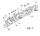
- the Coupling control part 90 has a locking recess 91 and a link pin 92, which in engages an S-shaped link slot 93 of a deployment lever 94, which on its one End is pivotally connected to the rearmost link 99 of a coupling element 95 and on at its other end carries a link pin 96, which is in the link slot 42 of the rearmost Fastening elements 20a engages.
- the coupling element 95 is in a plurality of links 97a to 97c divided, which are pivotally connected to each other via a joint 98.
- Each Link 97a to 97c has a cheek 101a to 101c, in which a locking recess 100a up to 100c.
- the rearmost member 99 has a laterally pivotable Bolt hammer 102, its head 103 in a bolt recess 104 of the guide rail 75 or can engage in the bolt recess 90.
- the coupling element 95 is - as for that Link 97c shown in Fig. 14 - slidably guided along the guide rail 75.
- front part 28 of the adjusting element 60 of the foremost slat 10d is a preferably designed as a threaded cable drive cable (not shown) in Drive connection.
- the drive cable extends to only a hint in FIG. 1 shown front drive unit 73.
- the front drive unit 73 can, as well the rear drive unit 87, an electric motor and a in a conventional manner Have reduction gears, one with the output of the reduction gear connected pinion is engaged with the corresponding drive cables.
- the support elements, and thus the slats 10, are all parallel to the roof plane.
- the Adjacent fasteners 20 are, as described above, by creating the rear Part 21 on the shoe 40 or the arm 37 and the counter-holder 80 alternately in Direction of displacement guided safely.
- the locking hammer 102 engages with one side of the head 103 in the roof Bolt recess 104, around the rearmost link 99, and thus the entire coupling element 95, to be locked firmly on the roof, the locking hammer thereby being in the locking recess 104 the other side of the head 103 is held on a wall of the coupling control part 90 is present.
- the rear link 99 is additionally by a stop 105 on the Guide rail 75 secured to the rear.
- the link pin 96 of the deployment lever 94 is located at the rear end 48 of the link slot 42 the rearmost fastener.
- the link pin 92 of the coupling control part 90 is in the Area of the rear end of the slot slot 93 of the opening lever 94.
- the front drive unit uses 73 force on the drive cable 59 on both sides of the roof opening 13 in the rearward direction Transfer direction.
- the drive movement of the drive unit in e.g. DE-PS-43 29 580 known way a pivoting of the wind deflector 16th
- the rear drive device 87 is activated in order to Coupling control part 90 with respect to the rearmost link 99 of the coupling element 95 to the front push.
- the link pin 92 of the coupling control part 90 slides in the link slot 93 of the opening lever 94 to the front, due to the shape of the slot slot 93 of the deployment lever 94 is pivoted with the rear end upwards.
- This will also the link pin 96 raised, which due to its engagement in the link slot 42 of the rearmost fastening element 20a, in turn, an opening of the rearmost lamella 10a causes, whereby this with its rear edge over the (not shown) Sealing at the rear edge of the roof opening 13 is raised (see Fig. 6 and 10).
- the vehicle roof can also be designed so that the described swung out Position of the last lamella 10a can also be achieved regardless of whether the Wind deflector 16 is pivoted out beforehand or not, so that an additional Ventilation position is created.
- the link pin 96 of the deployment lever 94 is in the link slot 42 of the last Fastener 20a slidably guided.
- the further postponement of the Fastening element 20a to the rear relative to the link pin 96 of the deployment lever 94 causes a further opening movement of the last lamella 10a in addition to the displacement.
- the guide points of the fasteners are chosen so that the lifting of the rear At the end of the adjusting element 60, the end face 41 is lowered relative to the driver 23 of the preceding fastening element 20b.
- the shoe 40 and therefore also that rear ends of the previous fastener 20b also become light raised.
- By appropriate selection of the rotary levers or positions of the pivot points ensures that the rear edge of the penultimate Slat 10b by pivoting the following (last) slat 10a over the Front edge of the last lamella 10a is raised, so that sliding one over the other successive slats can take place.
- the fasteners 20a to d are thus coupled in such a way that a pivoting movement of the last Fastening element 20a a propagating forward and thereby strong weakening pivoting movement of the preceding fastening elements 20b to d causes. Due to the bias of the spring, the actuating arm 33 becomes everyone Relative movement between adjacent adjustment elements 60 tracked so that it always bears against the contact surface 25 of the rear part 21.
- the fastening elements 20 are rearward with respect to the coupling element 95 postponed.
- the bias by the spring reliably prevents the latch member 32 during the opening movement while passing a bolt recess 100 of the Coupling element e.g. snaps into it by a shock.
- the locking part 32 is arranged so that during the increasing opening movement of the adjusting element 60, the relative height of the locking part 32 in the course of the opening movement essentially does not change with respect to the cheek 101 of the coupling element 95. It takes place however, a rotational movement of the locking part 32 instead.
- the upper contact surface 69 of the Bolt part 32 is increasingly on the lower contact surface of the cheek 101 of the Coupling element 95.
- the curvature of the contact surface of the driver 23 or the end face 41 of the front Part 28 are chosen so that from a certain pivoting position of the adjusting element 60 the locking rocker 31 by engaging the upper contact surface 69 on the underside of the cheek 101 driving force from the previous adjusting element 60 to the following one Adjusting element 60 transmits.
- This is advantageous in that the overlap of the Contact surface 27 of the driver 23 with the end face 41 with increasing pivoting out becomes less and less, so that the pressure increases, which leads to damage to the corresponding contact surfaces 27 and 41 and in particular the boundary of these surfaces Edges 67 and 70 could lead.
- the corresponding elements are dimensioned so that the power transmission passes to the rocker rocker 31 in such a timely manner that one Damage is definitely avoided.
- the locking part 32 is now through the contact of the upper contact surface 68 of the actuating arm 33 on the underside 22 of the rear part 21 of the adjusting element 60 in engagement with the last locking recess 101a of the coupling element 95 held and causes in this way a roof-locked locking of the last fastening element 20a.
- the last slat is 10a thus secured against forward and backward movement.
- the foremost slat 10d is locked in position by the front drive 73 is rigid and self-locking via the drive cable in a conventional manner.
- the drive unit 73 applies force to the drive cable acting on the first lamella 10d on both sides of the roof opening 13 transmitted in the forward direction.
- the unlocked first slat 10d moves thereby moving forward.
- the shoe 40 of the second fastening element 20c slides in the link slot 42 of the first fastening element 20d.
- the first fastener 20d is partially pivoted backwards by the closing movement.
- a The second fastening element 20c cannot move in the closing direction, since the locking part 32 on the system of the actuating arm 33 of the rocker switch on the Bottom side 22 of the first fastening element 20d with the locking recess 100c in Engagement is held.
- the actuating arm 33 can after Move up so that the contact surface 61 of the locking part 32 slides on the Contact surface 86 of the bolt recess 100c is possible.
- the introduction of force into that Fastening element 20c occurs, as mentioned above, by fitting the shoe 40 of the fastening element 20c at the rear end 48 of the link slot 42 of the previous fastener 20d or by applying two others Contact surfaces on two adjacent adjusting elements 60.
- the locking part 32 moves thereby out of the bolt recess, whereby the roof-locked locking of Fastener 20c is lifted.
- the adjacent fasteners 20d and 20c are now coupled together for the closing movement.
- the closing process takes place in such a way that there is always a part the slats are coupled together and move together in the closing direction, while the remaining part of the slats with the common coupling element 95, i.e. roof-tight, locked and cannot participate in the closing movement.
- the last The movable and the first locked slats are each uncoupled from each other.
- the coupling of the first locked takes place Slat to the last movable slat very shortly after unlocking the first locked slat instead, i.e. almost at the same time.
- the rearmost fastening element 20a is also first fully swung out, uncoupled with the penultimate fastening element 20b and at the same time locked with the coupling element 95, etc., so that finally a slat package pushed together at the front edge of the roof opening 13 is obtained (see FIG. 3).
- the lamella composite can also be opened from the front and from the rear at the same time be, one pushed together in the middle of the roof opening 13 Plate pack receives (see Fig. 4).
- the wind deflector first poses 16 out.
- the coupling element 95 can also be formed in one piece from elastic material.
Landscapes
- Engineering & Computer Science (AREA)
- Mechanical Engineering (AREA)
- Fittings On The Vehicle Exterior For Carrying Loads, And Devices For Holding Or Mounting Articles (AREA)
- Lock And Its Accessories (AREA)
- Cooling, Air Intake And Gas Exhaust, And Fuel Tank Arrangements In Propulsion Units (AREA)
- Body Structure For Vehicles (AREA)
- Vehicle Interior And Exterior Ornaments, Soundproofing, And Insulation (AREA)
- Power-Operated Mechanisms For Wings (AREA)
Abstract
Description
- FIG. 1
- eine perspektivische schematische Ansicht eines Lamellendaches im teilweise geöffneten Zustand;
- FIG. 2
- eine Ansicht entsprechend FIG. 1 bei von vorn vollständig geöffneter Dachöffnung;
- FIG. 3
- eine Ansicht entsprechend FIG. 1 bei von hinten vollständig geöffneter Dachöffnung;
- FIG. 4
- eine Ansicht entsprechend FIG. 1 bei sowohl von vorn als auch von hinten vollständig geöffneter Dachöffnung;
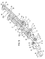
- FIG. 5
- eine perspektivische Ansicht der Verstellelemente zweier ausgeschwenkter Befestigungselemente;
- FIG. 6 und 7
- zwei unterschiedliche perspektivische Ansichten eines Teils des Koppelelements mit Koppelsteuerteil und zwei Riegelwippen;
- FIG. 8
- eine Seitenansicht eines Teils der Befestigungselemente und des Koppelelements mit Koppelsteuerteil in Schließstellung ;
- FIG. 9
- eine Ansicht wie FIG. 8, jeoch von unten gesehen;
- FIG. 10
- eine Ansicht wie FIG.8, jedoch mit über den hinteren Rand der Dachöffnung angehobener letzter Lamelle;
- FIG. 11
- eine Ansicht wie FIG. 8, jedoch in der Stellung von FIG. 2;
- FIG. 12
- eine Ansicht wie FIG. 8, jedoch in der Stellung von FIG. 4;
- FIG. 13
- die Schnittansicht entlang XIII-XIII in FIG. 8;
- FIG. 14
- die Schnittansicht entlang XIV-XIV in FIG. 12;
- FIG. 15
- die Schnittansicht entlang XV-XV in FIG. 12; und
- FIG. 16
- die Schnittansicht entlang XVI-XVI in FIG. 10.
- Fahrzeugdach
- 9
- Schiebelamellen
- 10a bis d
- feste Dachfläche
- 11
- Kraftfahrzeug
- 12
- Dachöffnung
- 13
- Verschieberichtung
- 14
- Windabweiser
- 16
- Befestigungselement
- 20a bis d
- hinterer Teil von 60
- 21
- Unterseite von 21
- 22
- Mitnehmer
- 23
- Ausnehmung in 23
- 24
- Anlagefläche von 53
- 25
- Innenfläche von 21
- 26
- vorderer Teil von 60
- 28
- Riegelwippe
- 31
- Riegelteil
- 32
- Betätigungsarm
- 33
- Arm
- 37
- Bohrung in 37
- 38
- Stift
- 39
- Schuh
- 40
- vordere Stirnfläche von 28
- 41
- Kulissenschlitz
- 42
- hinteres Ende von 42
- 48
- vorderes Ende von 42
- 49
- hinteres Ende von 21
- 53
- Kante zw. 61 u. 69
- 55
- Nase von 33
- 58
- Verstellelement (21+28)
- 60
- vordere obere Anlagefläche von 32
- 61
- vordere obere Anlagefläche von 33
- 62
- Kante
- 64
- Oberkante von 33
- 65
- obere Anlagefläche von 33
- 68
- obere Anlagefläche von 32
- 69
- Oberkante von 41
- 70
- vordere Antriebseinheit
- 73
- Führungsbahn für 90
- 73
- Führungsbahn
- 74
- Führungsschiene
- 75
- Gegenhalter
- 80
- äußere Anlagefläche von 80
- 81
- hintere Antriebseinheit
- 87
- Koppelsteuerteil
- 90
- Riegelausnehmung in 90
- 91
- Kulissenstift von 90
- 92
- Kulissenschlitz von 94
- 93
- Ausstellhebel
- 94
- Koppelelement
- 95
- Kulissenstift von 94
- 96
- Glieder von 95
- 97a-c
- Gelenke zwischen 97
- 98
- letztes Glied von 95
- 99
- Riegelausnehmungen
- 100a-c
- Wangen von 95
- 101a-c
- Riegelhammer von 99
- 102
- Hammerkopf von 102
- 103
- Riegelausnehmung in 75 für 103
- 104
- Anschlag (an 75)
- 105
Claims (14)
- Fahrzeugdach mit einer Folge von Deckelelementen (Lamellen 10a bis 10d) zum wahlweisen Verschließen oder mindestens teilweisen Freigeben einer Dachöffnung (13) in einer Dachfläche (11), wobei die Deckelelemente in der Schließstellung aneinander angrenzen und einen flächigen Verbund bilden, jede Lamelle an ihren Schmalseiten jeweils mit einem schwenkbaren Befestigungselement (20a bis 20d) verbunden ist und die Befestigungselemente entlang einer dachfesten Führungsbahn (74) geführt sind, wobei jeweils zwei benachbarte Befestigungselemente für eine gemeinsame Bewegung in Öffnungs- und Schließrichtung gekuppelt sind, solange sie nicht voll ausgeschwenkt sind, und entkuppelt sind, sobald eines der beiden Befestigungselemente seine voll ausgeschwenkte Stellung erreicht hat, und derart miteinander in Eingriff stehen, daß sie in entkuppeltem Zustand unter Ausschwenkung des noch nicht voll ausgeschwenkten Befestigungselements gegeneinander verstellbar sind; daß ein Befestigungselement in der voll ausgeschwenkten Lage unter dem Einfluß der Öffnungsbewegung des einen benachbarten Befestigungselements fest mit mindestens einem Teil der anderen bereits voll ausgeschwenkten Befestigungselementen verriegelbar ist und daß die Verriegelung eines voll ausgeschwenkten Befestigungselements mit den anderen mindestens einem Teil der noch voll ausgeschwenkten Befestigungslementen unter dem Einfluß der Schließbewegung des einen benachbarten Befestigungselements selbsttätig lösbar ist dadurch gekennzeichnet, daß mindestens ein Teil aller voll ausgeschwenkten Befestigungselemente (20a bis 20d) jeweils in festem Eingriff mit einem gemeinsamen Koppelelement (95) steht, welches entlang der dachfesten Führungsbahn (74) verschiebbar ist bzw. bzgl. dieser festsetzbar ist.
- Fahrzeugdach nach Anspruch 1, dadurch gekennzeichnet, daß das Koppelelement (95) in mindestens einer Position mit der dachfesten Führungsbahn (74) verriegelbar ist.
- Fahrzeugdach nach Anspruch 2, dadurch gekennzeichnet, daß ein von einer Antriebeinheit (87) zu einer Verschiebung entlang der Führungsbahn (74) angetriebenes Koppelsteuerteil (90) vorgesehen ist, welches mit dem Koppelelement (95) verriegelbar ist.
- Fahrzeugdach nach Anspruch 3, dadurch gekennzeichnet, daß das Koppelelement (95) eine Verriegelungsvorrichtung (Riegelhammer 102) zur Verriegelung mit einer dachfesten Führungsschiene (75) der Führungsbahn (74) bzw. mit dem Koppelsteuerteil (90) aufweist, die durch eine Verschiebung des Koppelsteuerteils bezüglich des Koppelelements in der Schließstellung des Deckelelementverbunds so betätigt wird, daß sie die Verriegelung mit der dachfesten Führungsschiene löst und die Verriegelung mit dem Koppelsteuerteil schließt.
- Fahrzeugdach nach Anspruch 4, dadurch gekennzeichnet, daß die Verriegelungsvorrichtung einen schwenkbaren Riegelhammer (102) umfaßt, der die entsprechende Verriegelung durch Eingriff in Riegelausnehmungen (104 bzw. 91) in der dachfesten Führungsbahn (74) bzw. in dem Koppelsteuerelement (90)herstellt.
- Fahrzeugdach nach Anspruch 3 oder 4, dadurch gekennzeichnet, daßeine zusätzliche Antriebseinheit (73) vorgesehen ist, um das vorderste Befestigungselement (20d) anzutreiben
- Fahrzeugdach nach einem der Ansprüche 3 bis 6, dadurch gekennzeichnet, daß in der Schließstellung des Deckelelementverbunds das Koppelelement (95) mit mit der dachfesten Führungsbahn (74) verriegelt ist, während das Koppelsteuerteil (90) bezüglich des Koppelelements verschiebbar ist, daß zu Beginn der Öffnungsbewegung das Koppelsteuerteil auf das Koppelelement zu nach vorn geschoben wird, wodurch das hinterste Befestigungselement (20a) ausgeschwenkt wird, das Koppelsteuerteil die Verriegelung des Koppelelements mit der Führungsbahn löst und eine Verriegelung des Koppelelements mit dem Koppelsteuerteil bewirkt und daß durch weiteres Nach-vorn-Schieben des Koppelsteuerelements ein Ausschwenken und anschließend eine Verriegelung des hintersten Befestigungselements mit dem Koppelelement bewirkt wird, wobei durch fortgesetztes Nach-vorn-Schieben des Koppelsteuerelements schließlich die Deckelelemente (Lamellen 10a bis 10d) zu einem Paket nach vorn zusammengeschoben werden.
- Fahrzeugdach nach einem der Ansprüche 3 bis 7, dadurch gekennzeichnet, daß das Koppelsteuerteil (90) derart mit dem hintersten Befestigungselement (20a) in Eingriff steht, daß eine Verschiebung des Koppelsteuerteils entlang der dachfesten Führungsbahn (74) ein Ausschwenken bzw. Zurückschwenken des hintersten Befestigungselements bewirkt.
- Fahrzeugdach nach Anspruch 8, dadurch gekennzeichnet, daß das Koppelsteuerteil (90) einen Ausstellhebel (94) betätigt, der schwenkbar an dem Koppelelement (95) befestigt ist und mit dem hintersten Befestigungselement (20a) zusammenwirkt.
- Fahrzeugdach nach Anspruch 9, dadurch gekennzeichnet, daß der Ausstellhebel (94) als Kulissenhebel ausgebildet ist, der mittels eines Kulissenstifts (96) in einen an dem letzten Befestigungselement (20a) ausgebildeten Kulissenschlitz (42) eingreift und seinerseits mit einem Kulissenschlitz (93) versehen ist, in welchen ein an dem Koppelsteuerteil (90) ausgebildeter Kulissenstift (92) eingreift.
- Fahrzeugdach nach einem der vorhergehenden Ansprüche, dadurch gekennzeichnet, daß das Koppelelement (95) mehrere Glieder (97 und 99) umfaßt, die schwenkbar miteinander verbunden sind.
- Fahrzeugdach nach einem der vorhergehenden Ansprüche, dadurch gekennzeichnet, daß außer für das vorderste Befestigungselelement (20d) pro Befestigungselelement (20a bis 20c) ein Koppelelement-Glied (97a bis 97c) vorgesehen ist.
- Fahrzeugdach nach einem der vorhergehenden Ansprüche, dadurch gekennzeichnet, daß die Verriegelung zwischen den Befestigungselementen (20a bis 20d) und dem Koppelelement (95) über ein Verriegelungselement erfolgt, das als Riegelwippe (31) ausgebildet ist, die in ihrem Mittelabschnitt schwenkbar gelagert ist, an ihrem einen Endabschnitt ein Riegelteil (32) und an ihrem anderen Endabschnitt einen Betätigungsarm (33) aufweist.
- Fahrzeugdach nach Anspruch 13, dadurch gekennzeichnet, daß das Koppelelement (95) für jedes Befestigungselement (20a bis 20c) mit Ausnahme des vordersten (20d) eine Riegelausnehmung (100a bis 100c) zur Aufnahme des Riegelteils (32) aufweist.
Applications Claiming Priority (2)
| Application Number | Priority Date | Filing Date | Title |
|---|---|---|---|
| DE19835535 | 1998-08-06 | ||
| DE19835535A DE19835535C1 (de) | 1998-08-06 | 1998-08-06 | Fahrzeugdach |
Publications (3)
| Publication Number | Publication Date |
|---|---|
| EP0978400A2 true EP0978400A2 (de) | 2000-02-09 |
| EP0978400A3 EP0978400A3 (de) | 2001-05-02 |
| EP0978400B1 EP0978400B1 (de) | 2005-01-19 |
Family
ID=7876653
Family Applications (1)
| Application Number | Title | Priority Date | Filing Date |
|---|---|---|---|
| EP99115388A Expired - Lifetime EP0978400B1 (de) | 1998-08-06 | 1999-08-04 | Fahrzeugdach |
Country Status (5)
| Country | Link |
|---|---|
| US (1) | US6457771B2 (de) |
| EP (1) | EP0978400B1 (de) |
| JP (1) | JP2000052774A (de) |
| AT (1) | ATE287341T1 (de) |
| DE (2) | DE19835535C1 (de) |
Cited By (2)
| Publication number | Priority date | Publication date | Assignee | Title |
|---|---|---|---|---|
| DE10148537A1 (de) * | 2001-10-01 | 2003-04-30 | Webasto Vehicle Sys Int Gmbh | Dachaufbau eines Fahrzeugs |
| DE10207729A1 (de) * | 2002-02-24 | 2003-09-11 | Webasto Vehicle Sys Int Gmbh | Fahrzeug mit einer schließbaren Dachöffnung |
Families Citing this family (20)
| Publication number | Priority date | Publication date | Assignee | Title |
|---|---|---|---|---|
| DE19959538C1 (de) * | 1999-12-09 | 2001-02-01 | Webasto Vehicle Sys Int Gmbh | Öffnungsfähiges Fahrzeugdach mit einer Folge von Deckelelementen |
| JP4243480B2 (ja) * | 2000-11-09 | 2009-03-25 | イナルファ・ルーフ・システムズ・グループ・ベーフェー | 車両用開放屋根構造体、並びにそのような開放屋根構造体を取り付けた車両 |
| WO2002038406A1 (en) * | 2000-11-09 | 2002-05-16 | Inalfa Industries B.V. | An open roof construction for a vehicle, as well as a vehicle fitted with such an open roof construction |
| US6485094B2 (en) * | 2000-12-06 | 2002-11-26 | Asc Incorporated | Automotive vehicle open air system |
| DE10119667A1 (de) * | 2001-04-20 | 2002-10-31 | Cts Fahrzeug Dachsysteme Gmbh | Lamellendach für Fahrzeuge |
| DE10119701A1 (de) * | 2001-04-20 | 2002-10-31 | Cts Fahrzeug Dachsysteme Gmbh | Lamellendach |
| DE10139977C2 (de) | 2001-08-21 | 2003-07-03 | Webasto Vehicle Sys Int Gmbh | Fahrzeug mit einer verschließbaren Dachöffnung |
| DE10140240A1 (de) * | 2001-08-22 | 2003-03-13 | Webasto Vehicle Sys Int Gmbh | Fahrzeug mit einem zu öffnenden Dach |
| DE10215966B4 (de) * | 2002-04-11 | 2004-07-08 | Webasto Vehicle Systems International Gmbh | Öffnungsfähiges Fahrzeugdach |
| DE10217147C1 (de) * | 2002-04-17 | 2003-10-16 | Webasto Vehicle Sys Int Gmbh | Windabweiser für öffnungsfähige Fahrzeugdächer |
| US20080081148A1 (en) * | 2006-09-13 | 2008-04-03 | Kenneth Bond | Panel having a frame bonded thereto |
| DE102007029582A1 (de) * | 2007-06-26 | 2009-01-08 | GM Global Technology Operations, Inc., Detroit | Kraftfahrzeugdach |
| DE102007029580A1 (de) * | 2007-06-26 | 2009-01-08 | GM Global Technology Operations, Inc., Detroit | Kraftfahrzeugdach |
| EP2052898B1 (de) * | 2007-10-23 | 2011-08-03 | Kanto Auto Works, Ltd. | Schiebedachstruktur und Fahrzeug, das diese Struktur aufweist |
| DE102008046331B4 (de) * | 2008-09-09 | 2010-06-24 | Webasto Ag | Fahrzeugdach |
| KR101033878B1 (ko) * | 2009-08-27 | 2011-05-13 | 국민대학교산학협력단 | 컨버터블 차량의 슬라이딩 가이드 레일 |
| EP2644422B1 (de) * | 2012-03-26 | 2014-10-15 | Inalfa Roof Systems Group B.V. | Offene Dachkonstruktion für ein Fahrzeug |
| AU2015279245C1 (en) * | 2014-06-25 | 2018-10-04 | Shell Internationale Research Maatschappij B.V. | Shoe for a tubular element in a wellbore |
| US9855828B1 (en) * | 2016-11-03 | 2018-01-02 | Tayih Kenmos Auto Parts Co., Ltd. | Tonneau cover |
| CN115056701B (zh) * | 2022-06-15 | 2023-11-03 | 成都锦城学院 | 一种养蜂车车窗结构 |
Citations (3)
| Publication number | Priority date | Publication date | Assignee | Title |
|---|---|---|---|---|
| DE19529522C1 (de) | 1995-08-11 | 1996-08-29 | Webasto Karosseriesysteme | Fahrzeugdach mit einer Folge von ausstellbaren Lamellen |
| DE19529702C1 (de) | 1995-08-11 | 1996-09-12 | Webasto Karosseriesysteme | Fahrzeugdach mit einer Folge von ausstellbaren Lamellen |
| DE19608916C1 (de) | 1996-03-07 | 1997-04-17 | Webasto Karosseriesysteme | Fahrzeugdach mit einer Folge von ausstellbaren Deckelelementen |
Family Cites Families (4)
| Publication number | Priority date | Publication date | Assignee | Title |
|---|---|---|---|---|
| DE3732548A1 (de) * | 1987-09-26 | 1989-04-20 | Ford Werke Ag | Ausstell-schiebedach fuer kraftfahrzeuge |
| DE4129860C1 (de) * | 1991-09-07 | 1992-09-17 | Webasto Ag Fahrzeugtechnik, 8035 Stockdorf, De | |
| DE4142265C1 (en) * | 1991-12-20 | 1992-12-17 | Webasto Ag Fahrzeugtechnik, 8035 Stockdorf, De | Car sun roof with rigid lid(s) - has roof railing with side screens along its length in section protruding beyond roof skin in sun roof open position |
| DE4407286C1 (de) * | 1994-03-04 | 1995-05-04 | Webasto Karosseriesysteme | Fahrzeugdach mit einer Folge von Lamellen |
-
1998
- 1998-08-06 DE DE19835535A patent/DE19835535C1/de not_active Expired - Fee Related
-
1999
- 1999-08-03 JP JP11220237A patent/JP2000052774A/ja active Pending
- 1999-08-04 EP EP99115388A patent/EP0978400B1/de not_active Expired - Lifetime
- 1999-08-04 AT AT99115388T patent/ATE287341T1/de not_active IP Right Cessation
- 1999-08-04 DE DE59911466T patent/DE59911466D1/de not_active Expired - Lifetime
- 1999-08-06 US US09/368,905 patent/US6457771B2/en not_active Expired - Lifetime
Patent Citations (3)
| Publication number | Priority date | Publication date | Assignee | Title |
|---|---|---|---|---|
| DE19529522C1 (de) | 1995-08-11 | 1996-08-29 | Webasto Karosseriesysteme | Fahrzeugdach mit einer Folge von ausstellbaren Lamellen |
| DE19529702C1 (de) | 1995-08-11 | 1996-09-12 | Webasto Karosseriesysteme | Fahrzeugdach mit einer Folge von ausstellbaren Lamellen |
| DE19608916C1 (de) | 1996-03-07 | 1997-04-17 | Webasto Karosseriesysteme | Fahrzeugdach mit einer Folge von ausstellbaren Deckelelementen |
Cited By (3)
| Publication number | Priority date | Publication date | Assignee | Title |
|---|---|---|---|---|
| DE10148537A1 (de) * | 2001-10-01 | 2003-04-30 | Webasto Vehicle Sys Int Gmbh | Dachaufbau eines Fahrzeugs |
| DE10207729A1 (de) * | 2002-02-24 | 2003-09-11 | Webasto Vehicle Sys Int Gmbh | Fahrzeug mit einer schließbaren Dachöffnung |
| DE10207729C2 (de) * | 2002-02-24 | 2003-12-24 | Webasto Vehicle Sys Int Gmbh | Fahrzeug mit einer schließbaren Dachöffnung |
Also Published As
| Publication number | Publication date |
|---|---|
| DE59911466D1 (de) | 2005-02-24 |
| JP2000052774A (ja) | 2000-02-22 |
| DE19835535C1 (de) | 1999-10-07 |
| EP0978400A3 (de) | 2001-05-02 |
| ATE287341T1 (de) | 2005-02-15 |
| EP0978400B1 (de) | 2005-01-19 |
| US6457771B2 (en) | 2002-10-01 |
| US20020005657A1 (en) | 2002-01-17 |
Similar Documents
| Publication | Publication Date | Title |
|---|---|---|
| EP0794077B1 (de) | Fahrzeugdach mit einer Folge von ausstellbaren Deckelelementen | |
| EP0978400B1 (de) | Fahrzeugdach | |
| EP0727331B1 (de) | Fahrzeugdach mit zwei Deckelelementen | |
| EP0591644B1 (de) | Fahrzeugdach mit einer Folge von Lamellen | |
| DE102006002064B4 (de) | Fahrzeugdach mit einem oberhalb eines festen Dachabschnitts verschiebbaren Deckel | |
| DE69915122T2 (de) | Konstruktion eines öffnungsfähigen fahrzeugdaches | |
| DE69829979T3 (de) | Verfahren zum öffnen und schliessen einer öffnungsfähigen dachherstellung für ein fahrzeug mit einer öffnung im festen dach, sowie solche öffnungsfähige dachherstellung | |
| DE4127624C1 (de) | ||
| WO2018104019A1 (de) | Anordnung für einen deckel für ein fahrzeugdach | |
| DE19542884C1 (de) | Fahrzeugdach mit einer Folge von ausstellbaren Lamellen | |
| DE4329580C1 (de) | Fahrzeugdach mit einer Folge von Lamellen | |
| EP0734895B1 (de) | Fahrzeugdach | |
| DE19529702C1 (de) | Fahrzeugdach mit einer Folge von ausstellbaren Lamellen | |
| DE4329583C1 (de) | Fahrzeugdach mit einer Folge von Lamellen | |
| DE19902150A1 (de) | Ausstellvorrichtung für einen an einem Rahmen schwenkbar angebrachten Kipp- oder Dreh-Kipp-Flügel | |
| EP1310395B1 (de) | Schiebesystem zum Verschliessen und Freigeben einer Dachöffnung | |
| DE60221716T2 (de) | Dachanordnung für ein fahrzeug | |
| DE102006056940A1 (de) | Sonnenschutzpaneelvorrichtung | |
| DE19654558C2 (de) | Schiebedach | |
| DE19856873C1 (de) | Lamellendach für eine Dachöffnung eines Kraftfahrzeugs | |
| DE19529522C1 (de) | Fahrzeugdach mit einer Folge von ausstellbaren Lamellen | |
| EP1809503A1 (de) | Schiebedachvorrichtung für kraftfahrzeuge | |
| EP1403113B1 (de) | Schiebedach für ein Kraftfahrzeug | |
| DE10137650A1 (de) | Windabweiser für ein Fahrzeugdach | |
| EP1071572A1 (de) | Verstellvorrichtung für ein multispoilerdach für fahrzeuge |
Legal Events
| Date | Code | Title | Description |
|---|---|---|---|
| PUAI | Public reference made under article 153(3) epc to a published international application that has entered the european phase |
Free format text: ORIGINAL CODE: 0009012 |
|
| AK | Designated contracting states |
Kind code of ref document: A2 Designated state(s): AT BE CH CY DE DK ES FI FR GB GR IE IT LI LU MC NL PT SE |
|
| AX | Request for extension of the european patent |
Free format text: AL;LT;LV;MK;RO;SI |
|
| PUAL | Search report despatched |
Free format text: ORIGINAL CODE: 0009013 |
|
| AK | Designated contracting states |
Kind code of ref document: A3 Designated state(s): AT BE CH CY DE DK ES FI FR GB GR IE IT LI LU MC NL PT SE |
|
| AX | Request for extension of the european patent |
Free format text: AL;LT;LV;MK;RO;SI |
|
| 17P | Request for examination filed |
Effective date: 20011005 |
|
| AKX | Designation fees paid |
Free format text: AT BE CH CY DE DK ES FI FR GB GR IE IT LI LU MC NL PT SE |
|
| GRAP | Despatch of communication of intention to grant a patent |
Free format text: ORIGINAL CODE: EPIDOSNIGR1 |
|
| GRAS | Grant fee paid |
Free format text: ORIGINAL CODE: EPIDOSNIGR3 |
|
| GRAA | (expected) grant |
Free format text: ORIGINAL CODE: 0009210 |
|
| AK | Designated contracting states |
Kind code of ref document: B1 Designated state(s): AT BE CH CY DE DK ES FI FR GB GR IE IT LI LU MC NL PT SE |
|
| PG25 | Lapsed in a contracting state [announced via postgrant information from national office to epo] |
Ref country code: IT Free format text: LAPSE BECAUSE OF FAILURE TO SUBMIT A TRANSLATION OF THE DESCRIPTION OR TO PAY THE FEE WITHIN THE PRESCRIBED TIME-LIMIT;WARNING: LAPSES OF ITALIAN PATENTS WITH EFFECTIVE DATE BEFORE 2007 MAY HAVE OCCURRED AT ANY TIME BEFORE 2007. THE CORRECT EFFECTIVE DATE MAY BE DIFFERENT FROM THE ONE RECORDED. Effective date: 20050119 Ref country code: IE Free format text: LAPSE BECAUSE OF FAILURE TO SUBMIT A TRANSLATION OF THE DESCRIPTION OR TO PAY THE FEE WITHIN THE PRESCRIBED TIME-LIMIT Effective date: 20050119 Ref country code: FI Free format text: LAPSE BECAUSE OF FAILURE TO SUBMIT A TRANSLATION OF THE DESCRIPTION OR TO PAY THE FEE WITHIN THE PRESCRIBED TIME-LIMIT Effective date: 20050119 |
|
| REG | Reference to a national code |
Ref country code: GB Ref legal event code: FG4D Free format text: NOT ENGLISH |
|
| REG | Reference to a national code |
Ref country code: CH Ref legal event code: EP |
|
| REG | Reference to a national code |
Ref country code: IE Ref legal event code: FG4D Free format text: GERMAN |
|
| REF | Corresponds to: |
Ref document number: 59911466 Country of ref document: DE Date of ref document: 20050224 Kind code of ref document: P |
|
| GBT | Gb: translation of ep patent filed (gb section 77(6)(a)/1977) |
Effective date: 20050302 |
|
| PG25 | Lapsed in a contracting state [announced via postgrant information from national office to epo] |
Ref country code: SE Free format text: LAPSE BECAUSE OF FAILURE TO SUBMIT A TRANSLATION OF THE DESCRIPTION OR TO PAY THE FEE WITHIN THE PRESCRIBED TIME-LIMIT Effective date: 20050419 Ref country code: GR Free format text: LAPSE BECAUSE OF FAILURE TO SUBMIT A TRANSLATION OF THE DESCRIPTION OR TO PAY THE FEE WITHIN THE PRESCRIBED TIME-LIMIT Effective date: 20050419 Ref country code: DK Free format text: LAPSE BECAUSE OF FAILURE TO SUBMIT A TRANSLATION OF THE DESCRIPTION OR TO PAY THE FEE WITHIN THE PRESCRIBED TIME-LIMIT Effective date: 20050419 |
|
| PG25 | Lapsed in a contracting state [announced via postgrant information from national office to epo] |
Ref country code: ES Free format text: LAPSE BECAUSE OF FAILURE TO SUBMIT A TRANSLATION OF THE DESCRIPTION OR TO PAY THE FEE WITHIN THE PRESCRIBED TIME-LIMIT Effective date: 20050430 |
|
| REG | Reference to a national code |
Ref country code: FR Ref legal event code: CD |
|
| PG25 | Lapsed in a contracting state [announced via postgrant information from national office to epo] |
Ref country code: LU Free format text: LAPSE BECAUSE OF NON-PAYMENT OF DUE FEES Effective date: 20050804 Ref country code: CY Free format text: LAPSE BECAUSE OF FAILURE TO SUBMIT A TRANSLATION OF THE DESCRIPTION OR TO PAY THE FEE WITHIN THE PRESCRIBED TIME-LIMIT Effective date: 20050804 Ref country code: AT Free format text: LAPSE BECAUSE OF NON-PAYMENT OF DUE FEES Effective date: 20050804 |
|
| REG | Reference to a national code |
Ref country code: IE Ref legal event code: FD4D |
|
| PG25 | Lapsed in a contracting state [announced via postgrant information from national office to epo] |
Ref country code: MC Free format text: LAPSE BECAUSE OF NON-PAYMENT OF DUE FEES Effective date: 20050831 Ref country code: LI Free format text: LAPSE BECAUSE OF NON-PAYMENT OF DUE FEES Effective date: 20050831 Ref country code: CH Free format text: LAPSE BECAUSE OF NON-PAYMENT OF DUE FEES Effective date: 20050831 Ref country code: BE Free format text: LAPSE BECAUSE OF NON-PAYMENT OF DUE FEES Effective date: 20050831 |
|
| PLBE | No opposition filed within time limit |
Free format text: ORIGINAL CODE: 0009261 |
|
| STAA | Information on the status of an ep patent application or granted ep patent |
Free format text: STATUS: NO OPPOSITION FILED WITHIN TIME LIMIT |
|
| ET | Fr: translation filed | ||
| 26N | No opposition filed |
Effective date: 20051020 |
|
| REG | Reference to a national code |
Ref country code: FR Ref legal event code: TP |
|
| REG | Reference to a national code |
Ref country code: CH Ref legal event code: PL |
|
| BERE | Be: lapsed |
Owner name: WEBASTO DACHSYSTEME G.M.B.H. Effective date: 20050831 |
|
| PG25 | Lapsed in a contracting state [announced via postgrant information from national office to epo] |
Ref country code: PT Free format text: LAPSE BECAUSE OF NON-PAYMENT OF DUE FEES Effective date: 20050619 |
|
| PGFP | Annual fee paid to national office [announced via postgrant information from national office to epo] |
Ref country code: DE Payment date: 20140821 Year of fee payment: 16 Ref country code: NL Payment date: 20140821 Year of fee payment: 16 |
|
| PGFP | Annual fee paid to national office [announced via postgrant information from national office to epo] |
Ref country code: GB Payment date: 20140821 Year of fee payment: 16 Ref country code: FR Payment date: 20140819 Year of fee payment: 16 |
|
| REG | Reference to a national code |
Ref country code: DE Ref legal event code: R119 Ref document number: 59911466 Country of ref document: DE |
|
| GBPC | Gb: european patent ceased through non-payment of renewal fee |
Effective date: 20150804 |
|
| REG | Reference to a national code |
Ref country code: NL Ref legal event code: MM Effective date: 20150901 |
|
| REG | Reference to a national code |
Ref country code: FR Ref legal event code: ST Effective date: 20160429 |
|
| PG25 | Lapsed in a contracting state [announced via postgrant information from national office to epo] |
Ref country code: NL Free format text: LAPSE BECAUSE OF NON-PAYMENT OF DUE FEES Effective date: 20150901 |
|
| PG25 | Lapsed in a contracting state [announced via postgrant information from national office to epo] |
Ref country code: DE Free format text: LAPSE BECAUSE OF NON-PAYMENT OF DUE FEES Effective date: 20160301 Ref country code: GB Free format text: LAPSE BECAUSE OF NON-PAYMENT OF DUE FEES Effective date: 20150804 |
|
| PG25 | Lapsed in a contracting state [announced via postgrant information from national office to epo] |
Ref country code: FR Free format text: LAPSE BECAUSE OF NON-PAYMENT OF DUE FEES Effective date: 20150831 |