EP0978437B1 - Chariot élévateur à fourche - Google Patents
Chariot élévateur à fourche Download PDFInfo
- Publication number
- EP0978437B1 EP0978437B1 EP19980114685 EP98114685A EP0978437B1 EP 0978437 B1 EP0978437 B1 EP 0978437B1 EP 19980114685 EP19980114685 EP 19980114685 EP 98114685 A EP98114685 A EP 98114685A EP 0978437 B1 EP0978437 B1 EP 0978437B1
- Authority
- EP
- European Patent Office
- Prior art keywords
- fork
- lift truck
- spring
- annular groove
- truck according
- Prior art date
- Legal status (The legal status is an assumption and is not a legal conclusion. Google has not performed a legal analysis and makes no representation as to the accuracy of the status listed.)
- Expired - Lifetime
Links
- 230000005540 biological transmission Effects 0.000 description 17
- 238000011161 development Methods 0.000 description 1
- 230000018109 developmental process Effects 0.000 description 1
- 238000006073 displacement reaction Methods 0.000 description 1
- 230000000694 effects Effects 0.000 description 1
- 238000009434 installation Methods 0.000 description 1
- 238000012423 maintenance Methods 0.000 description 1
- 230000000149 penetrating effect Effects 0.000 description 1
- 230000007704 transition Effects 0.000 description 1
Images

Classifications
-
- B—PERFORMING OPERATIONS; TRANSPORTING
- B62—LAND VEHICLES FOR TRAVELLING OTHERWISE THAN ON RAILS
- B62B—HAND-PROPELLED VEHICLES, e.g. HAND CARTS OR PERAMBULATORS; SLEDGES
- B62B3/00—Hand carts having more than one axis carrying transport wheels; Steering devices therefor; Equipment therefor
- B62B3/04—Hand carts having more than one axis carrying transport wheels; Steering devices therefor; Equipment therefor involving means for grappling or securing in place objects to be carried; Loading or unloading equipment
- B62B3/06—Hand carts having more than one axis carrying transport wheels; Steering devices therefor; Equipment therefor involving means for grappling or securing in place objects to be carried; Loading or unloading equipment for simply clearing the load from the ground
- B62B3/0618—Hand carts having more than one axis carrying transport wheels; Steering devices therefor; Equipment therefor involving means for grappling or securing in place objects to be carried; Loading or unloading equipment for simply clearing the load from the ground using fluid lifting mechanisms
Definitions
- the invention relates to a pallet truck with a steerable drive part and a fork arms Load part that can be raised by means of at least one hydraulic unit is, the cylinder and piston rod between two the drive part or the power transmission parts assigned to the load part arranged and each by a releasable connecting part are attached.
- Such a pallet truck is generally known, see e.g. U.S.-A-3,188,107. It is or each hydraulic unit with bolts or dowel pins, which extend through the cylinder base and the piston rod end, connected to the power transmission parts and in fixed in its installation position.
- the invention is based on the object or to connect each hydraulic unit so that it is on assemble and disassemble easily and without special tools leaves.
- At least one of the two the hydraulic unit in its installed position holding connecting parts a radially in the connecting position insertable spring pin that springs open and then partially in an annular groove on the cylinder or on the piston rod springs and partially into at least one circumferential slot engages in the plane of the annular groove in a holding part of the arm transmission part is formed.
- the spring connector provided according to the invention is replaced by a mere radial displacement in relation to the hydraulic unit installed and disassembled. This ensures that the spring pin is inherent Spring force the connection position, making an undesirable Solving is impossible. It has a simplifying effect also during assembly that the parts to be connected only have to be roughly aligned with each other because during assembly the spring pin itself the exact mutual alignment of the parts to be connected. Furthermore, the lifting forces from the vertically arranged hydraulic unit directly below Bypassing the spring pin on the power transmission part in question are transmitted so that the spring pin only must take over a position securing function and accordingly weak but easy to handle. That too favors the assembly and disassembly of the hydraulic unit.
- the pallet truck 1 has a front drive part 2, which is supported on wheels 3, and one rear load part 4, of which the vertically towering battery housing 5 and two fork arms 6 and 7 (without the outer ends) are shown.
- the fork arms 6 and 7 are close to theirs rear ends roll up for support on the floor.
- the load part 4 is - after driving under a pallet with the Fork arms 6 and 7 - raise to lift the load off the ground and to be able to move by means of the pallet truck 1.
- To this Raising (and lowering) the load part 4 are two hydraulic units 8 and 9 provided in a vertical arrangement in the drive part 2 are accommodated.
- the invention lies in the particular Attachment of the hydraulic units 8 and 9, wherein in the same attachment is provided in both cases. Accordingly the illustration according to FIG. 2 applies to both hydraulic units 8 and 9.
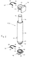
- Each hydraulic unit 8, 9 has a cylinder 10 with a Cylinder base 11 and connections 12, 13 for in Figure 1 not drawn hydraulic lines and one in the cylinder 10 slidable pistons with a piston rod 14 that out protrudes from the cylinder 10.
- the outer end of the piston rod 14 is provided with an annular groove 15, and is on the cylinder bottom 11 an extension corresponding to the diameter of the piston rod 14 16 integrally formed, which has a corresponding annular groove 17.
- the hydraulic unit 8, 9 are assigned to the drive part 2 and attached to this lower power transmission part 18 and one associated with the load part 4 and connected to it assigned upper power transmission part 19.
- the power transmission parts 18 and 19 have a cylindrical one-sided open Bore 20 for receiving the extension 16 with the annular groove 17 or the end of the piston rod provided with the annular groove 15 14 on.
- An end face 21 closes the bore 20 from the outside and forms an axial system for the extension 16 of the cylinder base 11 or for the end of the piston rod 14. Accordingly, the assembled hydraulic unit 8, 9 is between the two power transmission parts 18 and 19 clamped and the lifting forces are transmitted to the end faces 21.
- a lower spring pin 26 and an upper spring pin 27 provided in the same Way as a wire spring with an approximately circular arc Middle section 28 and two outwardly bent end sections 29, 30 are formed, each with a smaller Half-arches 31 and 32 are provided.
- the arcuate central section 28 has a the diameter of the bottom of the Ring grooves 15, 17 adapted inner diameter and extends itself over a little more than 180 °, so that between the two transitions from the middle section 28 to the end section 29 and End portion 30 a spring opening 33 is formed, the width is below the diameter of the ring groove bottom.
- the piston rod 14 is also by means of of the upper spring connector 27 on the holding part 23 of the upper power transmission part 19 fixed by the upper spring pin 27 and solved accordingly when disassembling.
Landscapes
- Engineering & Computer Science (AREA)
- Chemical & Material Sciences (AREA)
- Combustion & Propulsion (AREA)
- Transportation (AREA)
- Mechanical Engineering (AREA)
- Forklifts And Lifting Vehicles (AREA)
Claims (5)
- Chariot élévateur à fourche comprenant une partie d'entraínement (2) articulée et une partie de chargement (4) qui présente les bras de fourche (6, 7) et qui peut être relevée au moyen d'au moins un groupe hydraulique (8, 9) dont le cylindre (10) et la tige du piston (14) sont disposés entre deux parties de transmission de force (18, 19) associées respectivement à la partie d'entraínement (2) et à la partie de chargement (4) et qui sont fixés chacun par une pièce de liaison (26, 27) libérable, caractérisé en ce qu'au moins l'une des deux pièces de liaison (26, 27) qui maintiennent le groupe hydraulique (8, 9) dans sa position de montage est un étrier élastique (26, 27) qui peut être enfoncé radialement dans la position de liaison, qui se déploie et s'enfonce alors élastiquement en partie dans une rainure annulaire (15, 17) ménagée sur le cylindre (10) ou sur la tige de piston (14) et qui s'engage en partie dans au moins une fente périphérique (24, 25) qui est réalisée dans une pièce de maintien (22, 23) de la partie de transmission de force (18 ou 19) dans le plan de la rainure annulaire (15, 17).
- Chariot élévateur à fourche selon la revendication 1, caractérisé en ce que la pièce de maintien (22, 23) qui présente la fente périphérique (24, 25) est formée par une partie de la partie de transmission de force (18, 19) concernée qui ne transfère pas de force de levage.
- Chariot élévateur à fourche selon la revendication 1 ou 2, caractérisé en ce que l'étrier élastique (26, 27) est un ressort en fil qui présente une partie centrale (28) courbée à laquelle se raccordent deux parties d'extrémité (29, 30) courbées vers l'extérieur, la partie centrale (28) s'étendant sur plus de 180° et formant une ouverture de ressort (33) dont la largeur est inférieure au diamètre du fond de la rainure annulaire (15, 17).
- Chariot élévateur à fourche selon la revendication 3, caractérisé en ce que les parties d'extrémité (29, 30) du ressort en fil (26, 27) sont dotées de petits demi-cercles (31, 32) pour faciliter leur déploiement lors de leur libération.
- Chariot élévateur à fourche selon la revendication 3 ou 4, caractérisé en ce que les parties d'extrémité (29, 30) ou les demi-cercles (31, 32) du ressort en fil (26, 27) monté s'engagent dans des fentes périphériques (24, 25) respectives, opposées l'une à l'autre et à distance l'une de l'autre, de la pièce de maintien (22, 23).
Priority Applications (2)
| Application Number | Priority Date | Filing Date | Title |
|---|---|---|---|
| DE59808367T DE59808367D1 (de) | 1998-08-05 | 1998-08-05 | Gabelhubwagen |
| EP19980114685 EP0978437B1 (fr) | 1998-08-05 | 1998-08-05 | Chariot élévateur à fourche |
Applications Claiming Priority (1)
| Application Number | Priority Date | Filing Date | Title |
|---|---|---|---|
| EP19980114685 EP0978437B1 (fr) | 1998-08-05 | 1998-08-05 | Chariot élévateur à fourche |
Publications (2)
| Publication Number | Publication Date |
|---|---|
| EP0978437A1 EP0978437A1 (fr) | 2000-02-09 |
| EP0978437B1 true EP0978437B1 (fr) | 2003-05-14 |
Family
ID=8232405
Family Applications (1)
| Application Number | Title | Priority Date | Filing Date |
|---|---|---|---|
| EP19980114685 Expired - Lifetime EP0978437B1 (fr) | 1998-08-05 | 1998-08-05 | Chariot élévateur à fourche |
Country Status (2)
| Country | Link |
|---|---|
| EP (1) | EP0978437B1 (fr) |
| DE (1) | DE59808367D1 (fr) |
Families Citing this family (1)
| Publication number | Priority date | Publication date | Assignee | Title |
|---|---|---|---|---|
| JP2005517587A (ja) | 2002-02-20 | 2005-06-16 | ボアマン ゲゼルシャフト ミット ベシュレンクテル ハフツング | フォークリフト車 |
Family Cites Families (1)
| Publication number | Priority date | Publication date | Assignee | Title |
|---|---|---|---|---|
| US3188107A (en) * | 1962-05-17 | 1965-06-08 | Yale & Towne Inc | Lift truck |
-
1998
- 1998-08-05 EP EP19980114685 patent/EP0978437B1/fr not_active Expired - Lifetime
- 1998-08-05 DE DE59808367T patent/DE59808367D1/de not_active Expired - Lifetime
Also Published As
| Publication number | Publication date |
|---|---|
| DE59808367D1 (de) | 2003-06-18 |
| EP0978437A1 (fr) | 2000-02-09 |
Similar Documents
| Publication | Publication Date | Title |
|---|---|---|
| DE19526833B4 (de) | Schnellspannsystem | |
| EP2046614B1 (fr) | Dispositif de base pour supporter un dispositif de support ou de levage | |
| EP0622557B1 (fr) | Accouplement élastique | |
| DE9205097U1 (de) | Lüfter mit einem eine topfförmige Nabe aufweisenden Lüfterrad | |
| DE19830890B4 (de) | Dreiringnadellagerung für einen Pumpenteil | |
| DE19615007A1 (de) | Getriebe-Einheit | |
| DE4309022A1 (de) | Gelenk für Wagenheber | |
| DE3008210A1 (de) | Gelenkgabelkopf, insbesondere zum anlenken einer ladeschaufel an einen tragarm einer ladeschwinge | |
| DE29824298U1 (de) | Hebeeinrichtung zum Anheben schwerer Lasten, insbesondere entgleister Schienenfahrzeuge | |
| EP1616104A1 (fr) | Element de fixation et couvercle, adapte a ce dernier, d'un verin hydraulique | |
| DE4214243A1 (de) | Lagerung fuer zwei zueinander abgewinkelte bauteile innerhalb eines gehaeuses | |
| EP0788951B1 (fr) | Bras d'essuie-glace d'un dispositif de balayage de pare-brise de véhicule | |
| EP0978437A1 (fr) | Chariot élévateur à fourche | |
| WO2002036991A1 (fr) | Differentiel destine a l"entrainement d"axe d"un vehicule | |
| DE2751607C2 (de) | Schnellösevorrichtung für Federspeicherbremszylinder, insbesondere für Kraftfahrzeugbremsen | |
| DE69001501T2 (de) | Foerderer. | |
| EP0972688A2 (fr) | Dispositif de levage avec fût de conduit et tube support | |
| DE60101513T2 (de) | Montierhilfe für Raupenkette | |
| DE19742190B4 (de) | Gabelhubwagen, insbesondere Niederhubkommisionierer | |
| DE102006009602A1 (de) | Traganordnung eines Behälters an einem tragenden Bauteil eines Lastkraftwagens | |
| DE19840426B4 (de) | Lenksäulenlagerung | |
| DE19734858A1 (de) | Vorderachsabtrieb eines Automatgetriebes | |
| DE69014728T2 (de) | Zahnstangenhubvorrichtung. | |
| DE4235345A1 (de) | Laufradanordnung für einen Kran | |
| DE4129149C2 (de) | Mit einem Motor verbindbares Zahn- oder Riemenrad |
Legal Events
| Date | Code | Title | Description |
|---|---|---|---|
| PUAI | Public reference made under article 153(3) epc to a published international application that has entered the european phase |
Free format text: ORIGINAL CODE: 0009012 |
|
| AK | Designated contracting states |
Kind code of ref document: A1 Designated state(s): BE DE FR GB LU NL |
|
| AX | Request for extension of the european patent |
Free format text: AL;LT;LV;MK;RO;SI |
|
| 17P | Request for examination filed |
Effective date: 20000216 |
|
| AKX | Designation fees paid |
Free format text: BE DE FR GB LU NL |
|
| GRAH | Despatch of communication of intention to grant a patent |
Free format text: ORIGINAL CODE: EPIDOS IGRA |
|
| GRAH | Despatch of communication of intention to grant a patent |
Free format text: ORIGINAL CODE: EPIDOS IGRA |
|
| GRAA | (expected) grant |
Free format text: ORIGINAL CODE: 0009210 |
|
| AK | Designated contracting states |
Designated state(s): BE DE FR GB LU NL |
|
| PG25 | Lapsed in a contracting state [announced via postgrant information from national office to epo] |
Ref country code: NL Free format text: LAPSE BECAUSE OF FAILURE TO SUBMIT A TRANSLATION OF THE DESCRIPTION OR TO PAY THE FEE WITHIN THE PRESCRIBED TIME-LIMIT Effective date: 20030514 |
|
| REG | Reference to a national code |
Ref country code: GB Ref legal event code: FG4D Free format text: NOT ENGLISH |
|
| REF | Corresponds to: |
Ref document number: 59808367 Country of ref document: DE Date of ref document: 20030618 Kind code of ref document: P |
|
| PG25 | Lapsed in a contracting state [announced via postgrant information from national office to epo] |
Ref country code: LU Free format text: LAPSE BECAUSE OF NON-PAYMENT OF DUE FEES Effective date: 20030805 |
|
| PG25 | Lapsed in a contracting state [announced via postgrant information from national office to epo] |
Ref country code: BE Free format text: LAPSE BECAUSE OF NON-PAYMENT OF DUE FEES Effective date: 20030831 |
|
| GBT | Gb: translation of ep patent filed (gb section 77(6)(a)/1977) | ||
| NLV1 | Nl: lapsed or annulled due to failure to fulfill the requirements of art. 29p and 29m of the patents act | ||
| BERE | Be: lapsed |
Owner name: *CROWN GABELSTAPLER G.M.B.H. Effective date: 20030831 |
|
| ET | Fr: translation filed | ||
| PLBE | No opposition filed within time limit |
Free format text: ORIGINAL CODE: 0009261 |
|
| STAA | Information on the status of an ep patent application or granted ep patent |
Free format text: STATUS: NO OPPOSITION FILED WITHIN TIME LIMIT |
|
| 26N | No opposition filed |
Effective date: 20040217 |
|
| REG | Reference to a national code |
Ref country code: GB Ref legal event code: 732E |
|
| REG | Reference to a national code |
Ref country code: FR Ref legal event code: TP |
|
| REG | Reference to a national code |
Ref country code: DE Ref legal event code: R082 Ref document number: 59808367 Country of ref document: DE Representative=s name: LEONHARD & PARTNER PATENTANWAELTE, DE Ref country code: DE Ref legal event code: R082 Ref document number: 59808367 Country of ref document: DE |
|
| REG | Reference to a national code |
Ref country code: DE Ref legal event code: R082 Ref document number: 59808367 Country of ref document: DE Representative=s name: LEONHARD & PARTNER PATENTANWAELTE, DE |
|
| REG | Reference to a national code |
Ref country code: FR Ref legal event code: CA Effective date: 20140227 |
|
| REG | Reference to a national code |
Ref country code: DE Ref legal event code: R082 Ref document number: 59808367 Country of ref document: DE Representative=s name: LEONHARD & PARTNER PATENTANWAELTE, DE Effective date: 20120515 Ref country code: DE Ref legal event code: R082 Ref document number: 59808367 Country of ref document: DE Representative=s name: LEONHARD & PARTNER PATENTANWAELTE, DE Effective date: 20140326 Ref country code: DE Ref legal event code: R081 Ref document number: 59808367 Country of ref document: DE Owner name: CROWN GABELSTAPLER GMBH & CO. KG, DE Free format text: FORMER OWNER: CROWN GABELSTAPLER GMBH & CO. KG, 80809 MUENCHEN, DE Effective date: 20140326 |
|
| REG | Reference to a national code |
Ref country code: FR Ref legal event code: PLFP Year of fee payment: 19 |
|
| REG | Reference to a national code |
Ref country code: FR Ref legal event code: PLFP Year of fee payment: 20 |
|
| PGFP | Annual fee paid to national office [announced via postgrant information from national office to epo] |
Ref country code: DE Payment date: 20170822 Year of fee payment: 20 Ref country code: GB Payment date: 20170822 Year of fee payment: 20 Ref country code: FR Payment date: 20170822 Year of fee payment: 20 |
|
| REG | Reference to a national code |
Ref country code: DE Ref legal event code: R071 Ref document number: 59808367 Country of ref document: DE |
|
| REG | Reference to a national code |
Ref country code: GB Ref legal event code: PE20 Expiry date: 20180804 |
|
| PG25 | Lapsed in a contracting state [announced via postgrant information from national office to epo] |
Ref country code: GB Free format text: LAPSE BECAUSE OF EXPIRATION OF PROTECTION Effective date: 20180804 |
|
| P01 | Opt-out of the competence of the unified patent court (upc) registered |
Effective date: 20230529 |