EP0978477A1 - Condensateur de gaz oxygene et procede correspondant - Google Patents
Condensateur de gaz oxygene et procede correspondant Download PDFInfo
- Publication number
- EP0978477A1 EP0978477A1 EP99903913A EP99903913A EP0978477A1 EP 0978477 A1 EP0978477 A1 EP 0978477A1 EP 99903913 A EP99903913 A EP 99903913A EP 99903913 A EP99903913 A EP 99903913A EP 0978477 A1 EP0978477 A1 EP 0978477A1
- Authority
- EP
- European Patent Office
- Prior art keywords
- oxygen gas
- gas
- adsorption
- air
- adsorption tower
- Prior art date
- Legal status (The legal status is an assumption and is not a legal conclusion. Google has not performed a legal analysis and makes no representation as to the accuracy of the status listed.)
- Withdrawn
Links
- MYMOFIZGZYHOMD-UHFFFAOYSA-N Dioxygen Chemical compound O=O MYMOFIZGZYHOMD-UHFFFAOYSA-N 0.000 title claims abstract description 112
- 229910001882 dioxygen Inorganic materials 0.000 title claims abstract description 112
- 238000000034 method Methods 0.000 title claims abstract description 24
- 238000001179 sorption measurement Methods 0.000 claims abstract description 119
- 230000008719 thickening Effects 0.000 claims abstract description 66
- 239000002994 raw material Substances 0.000 claims abstract description 29
- 238000007865 diluting Methods 0.000 claims abstract description 8
- 230000002035 prolonged effect Effects 0.000 claims abstract description 5
- 239000007789 gas Substances 0.000 claims description 25
- IJGRMHOSHXDMSA-UHFFFAOYSA-N Atomic nitrogen Chemical compound N#N IJGRMHOSHXDMSA-UHFFFAOYSA-N 0.000 claims description 23
- 239000003463 adsorbent Substances 0.000 claims description 22
- 229910001873 dinitrogen Inorganic materials 0.000 claims description 13
- 238000003795 desorption Methods 0.000 claims description 10
- 229920006395 saturated elastomer Polymers 0.000 claims description 6
- QVGXLLKOCUKJST-UHFFFAOYSA-N atomic oxygen Chemical compound [O] QVGXLLKOCUKJST-UHFFFAOYSA-N 0.000 description 16
- 239000001301 oxygen Substances 0.000 description 16
- 229910052760 oxygen Inorganic materials 0.000 description 16
- 238000010586 diagram Methods 0.000 description 12
- 238000002474 experimental method Methods 0.000 description 8
- 238000001816 cooling Methods 0.000 description 7
- 238000010521 absorption reaction Methods 0.000 description 6
- 229910052757 nitrogen Inorganic materials 0.000 description 5
- 238000012423 maintenance Methods 0.000 description 4
- 239000000112 cooling gas Substances 0.000 description 3
- 239000002184 metal Substances 0.000 description 3
- 239000002250 absorbent Substances 0.000 description 2
- 230000000052 comparative effect Effects 0.000 description 2
- 239000003344 environmental pollutant Substances 0.000 description 2
- 239000010419 fine particle Substances 0.000 description 2
- 230000005484 gravity Effects 0.000 description 2
- 231100000719 pollutant Toxicity 0.000 description 2
- 239000000843 powder Substances 0.000 description 2
- 230000029058 respiratory gaseous exchange Effects 0.000 description 2
- 238000010977 unit operation Methods 0.000 description 2
- OKTJSMMVPCPJKN-UHFFFAOYSA-N Carbon Chemical compound [C] OKTJSMMVPCPJKN-UHFFFAOYSA-N 0.000 description 1
- 206010021143 Hypoxia Diseases 0.000 description 1
- 239000004677 Nylon Substances 0.000 description 1
- CBENFWSGALASAD-UHFFFAOYSA-N Ozone Chemical compound [O-][O+]=O CBENFWSGALASAD-UHFFFAOYSA-N 0.000 description 1
- 229910021536 Zeolite Inorganic materials 0.000 description 1
- 230000002745 absorbent Effects 0.000 description 1
- 239000000853 adhesive Substances 0.000 description 1
- 230000001070 adhesive effect Effects 0.000 description 1
- 229910052799 carbon Inorganic materials 0.000 description 1
- 230000006835 compression Effects 0.000 description 1
- 238000007906 compression Methods 0.000 description 1
- 238000007796 conventional method Methods 0.000 description 1
- 230000007547 defect Effects 0.000 description 1
- 230000002950 deficient Effects 0.000 description 1
- HNPSIPDUKPIQMN-UHFFFAOYSA-N dioxosilane;oxo(oxoalumanyloxy)alumane Chemical compound O=[Si]=O.O=[Al]O[Al]=O HNPSIPDUKPIQMN-UHFFFAOYSA-N 0.000 description 1
- 230000000694 effects Effects 0.000 description 1
- 230000007774 longterm Effects 0.000 description 1
- 230000004199 lung function Effects 0.000 description 1
- 239000000463 material Substances 0.000 description 1
- 238000002156 mixing Methods 0.000 description 1
- 229920001778 nylon Polymers 0.000 description 1
- 206010036067 polydipsia Diseases 0.000 description 1
- 230000003449 preventive effect Effects 0.000 description 1
- 238000011084 recovery Methods 0.000 description 1
- 230000001172 regenerating effect Effects 0.000 description 1
- 238000007789 sealing Methods 0.000 description 1
- 230000003584 silencer Effects 0.000 description 1
- 230000000391 smoking effect Effects 0.000 description 1
- 230000002123 temporal effect Effects 0.000 description 1
- 230000000007 visual effect Effects 0.000 description 1
- 239000002023 wood Substances 0.000 description 1
- 239000010457 zeolite Substances 0.000 description 1
Images


Classifications
-
- B—PERFORMING OPERATIONS; TRANSPORTING
- B01—PHYSICAL OR CHEMICAL PROCESSES OR APPARATUS IN GENERAL
- B01D—SEPARATION
- B01D53/00—Separation of gases or vapours; Recovering vapours of volatile solvents from gases; Chemical or biological purification of waste gases, e.g. engine exhaust gases, smoke, fumes, flue gases, aerosols
- B01D53/02—Separation of gases or vapours; Recovering vapours of volatile solvents from gases; Chemical or biological purification of waste gases, e.g. engine exhaust gases, smoke, fumes, flue gases, aerosols by adsorption, e.g. preparative gas chromatography
- B01D53/04—Separation of gases or vapours; Recovering vapours of volatile solvents from gases; Chemical or biological purification of waste gases, e.g. engine exhaust gases, smoke, fumes, flue gases, aerosols by adsorption, e.g. preparative gas chromatography with stationary adsorbents
- B01D53/0407—Constructional details of adsorbing systems
- B01D53/0446—Means for feeding or distributing gases
-
- B—PERFORMING OPERATIONS; TRANSPORTING
- B01—PHYSICAL OR CHEMICAL PROCESSES OR APPARATUS IN GENERAL
- B01D—SEPARATION
- B01D53/00—Separation of gases or vapours; Recovering vapours of volatile solvents from gases; Chemical or biological purification of waste gases, e.g. engine exhaust gases, smoke, fumes, flue gases, aerosols
- B01D53/02—Separation of gases or vapours; Recovering vapours of volatile solvents from gases; Chemical or biological purification of waste gases, e.g. engine exhaust gases, smoke, fumes, flue gases, aerosols by adsorption, e.g. preparative gas chromatography
- B01D53/04—Separation of gases or vapours; Recovering vapours of volatile solvents from gases; Chemical or biological purification of waste gases, e.g. engine exhaust gases, smoke, fumes, flue gases, aerosols by adsorption, e.g. preparative gas chromatography with stationary adsorbents
- B01D53/0407—Constructional details of adsorbing systems
- B01D53/0423—Beds in columns
-
- C—CHEMISTRY; METALLURGY
- C01—INORGANIC CHEMISTRY
- C01B—NON-METALLIC ELEMENTS; COMPOUNDS THEREOF; METALLOIDS OR COMPOUNDS THEREOF NOT COVERED BY SUBCLASS C01C
- C01B13/00—Oxygen; Ozone; Oxides or hydroxides in general
- C01B13/02—Preparation of oxygen
- C01B13/0229—Purification or separation processes
- C01B13/0248—Physical processing only
- C01B13/0259—Physical processing only by adsorption on solids
-
- B—PERFORMING OPERATIONS; TRANSPORTING
- B01—PHYSICAL OR CHEMICAL PROCESSES OR APPARATUS IN GENERAL
- B01D—SEPARATION
- B01D2253/00—Adsorbents used in seperation treatment of gases and vapours
- B01D2253/10—Inorganic adsorbents
- B01D2253/102—Carbon
-
- B—PERFORMING OPERATIONS; TRANSPORTING
- B01—PHYSICAL OR CHEMICAL PROCESSES OR APPARATUS IN GENERAL
- B01D—SEPARATION
- B01D2253/00—Adsorbents used in seperation treatment of gases and vapours
- B01D2253/10—Inorganic adsorbents
- B01D2253/106—Silica or silicates
- B01D2253/108—Zeolites
-
- B—PERFORMING OPERATIONS; TRANSPORTING
- B01—PHYSICAL OR CHEMICAL PROCESSES OR APPARATUS IN GENERAL
- B01D—SEPARATION
- B01D2256/00—Main component in the product gas stream after treatment
- B01D2256/12—Oxygen
-
- B—PERFORMING OPERATIONS; TRANSPORTING
- B01—PHYSICAL OR CHEMICAL PROCESSES OR APPARATUS IN GENERAL
- B01D—SEPARATION
- B01D2257/00—Components to be removed
- B01D2257/10—Single element gases other than halogens
- B01D2257/102—Nitrogen
-
- B—PERFORMING OPERATIONS; TRANSPORTING
- B01—PHYSICAL OR CHEMICAL PROCESSES OR APPARATUS IN GENERAL
- B01D—SEPARATION
- B01D2259/00—Type of treatment
- B01D2259/40—Further details for adsorption processes and devices
- B01D2259/402—Further details for adsorption processes and devices using two beds
-
- B—PERFORMING OPERATIONS; TRANSPORTING
- B01—PHYSICAL OR CHEMICAL PROCESSES OR APPARATUS IN GENERAL
- B01D—SEPARATION
- B01D2259/00—Type of treatment
- B01D2259/45—Gas separation or purification devices adapted for specific applications
- B01D2259/4533—Gas separation or purification devices adapted for specific applications for medical purposes
-
- B—PERFORMING OPERATIONS; TRANSPORTING
- B01—PHYSICAL OR CHEMICAL PROCESSES OR APPARATUS IN GENERAL
- B01D—SEPARATION
- B01D53/00—Separation of gases or vapours; Recovering vapours of volatile solvents from gases; Chemical or biological purification of waste gases, e.g. engine exhaust gases, smoke, fumes, flue gases, aerosols
- B01D53/02—Separation of gases or vapours; Recovering vapours of volatile solvents from gases; Chemical or biological purification of waste gases, e.g. engine exhaust gases, smoke, fumes, flue gases, aerosols by adsorption, e.g. preparative gas chromatography
- B01D53/04—Separation of gases or vapours; Recovering vapours of volatile solvents from gases; Chemical or biological purification of waste gases, e.g. engine exhaust gases, smoke, fumes, flue gases, aerosols by adsorption, e.g. preparative gas chromatography with stationary adsorbents
- B01D53/047—Pressure swing adsorption
-
- C—CHEMISTRY; METALLURGY
- C01—INORGANIC CHEMISTRY
- C01B—NON-METALLIC ELEMENTS; COMPOUNDS THEREOF; METALLOIDS OR COMPOUNDS THEREOF NOT COVERED BY SUBCLASS C01C
- C01B2210/00—Purification or separation of specific gases
- C01B2210/0043—Impurity removed
- C01B2210/0046—Nitrogen
Definitions
- the present invention relates to an oxygen gas thickening method and an oxygen gas thickening apparatus which utilize pressure swing absorption (PSA) system.
- PSA pressure swing absorption
- Oxygen gas is used as an industrial oxygen source used for producing ozone gas, a medical oxygen source used by patients having low lung functions, and an auxiliary means to aid respiration in a temporal anoxemia condition after an extremely hard sport, long-term work or study or excessive drinking or smoking. Accordingly, there is a strong desire for oxygen supply apparatus.
- the PSA system is conventionally known as an apparatus which supplies oxygen and a method which enhances an oxygen concentration in air or thickens oxygen gas.
- a conventional example of oxygen thickening apparatus which adopts the PSA system has a configuration shown in Fig. 8.
- a reference numeral 21 represents an air filter
- a reference numeral 22 designates a compressor
- a reference numeral 23 denotes a raw material feeding path
- a reference numeral 25 represents a first adsorption tower
- a reference numeral 26 designates a second adsorption tower.
- An adsorbent such as active carbon or zeolite, for example, is charged in each of the first and second adsorption towers.
- Reference numerals 27 and 28 denote flow paths for thickened oxygen gas
- reference numerals 31, 32, 33, 34 and 35 represent solenoid valves
- reference numerals 36 and 37 designate back-flow check valves
- a reference numeral 38 denotes a buffer reservoir
- a reference numeral 39 represents a pressure regulator valve
- a reference numeral 41 designates a bypass circuit for diluting air
- a reference numeral 42 denotes a flow control valve
- a reference numeral 43 represents a back-flow check valve
- a reference numeral 44 designates an exhaust desorbed gas
- a reference numeral 45 denotes an orifice for supplying a definite amount of oxygen gas thickened by the adsorption tower which operates for desorption of adsorbed nitrogen gas in a high pressure condition to the other adsorption tower which operates for desorption in a low pressure condition.
- the apparatus shown in Fig. 8 feeds raw material air through the air filter 21, compresses the air to a desired pressure with the air compressor 22 and supplies the compressed air into the first adsorption tower 25 or the second adsorption tower 26 by way of the raw material flow path 23.
- the apparatus supplies the air alternately to the first adsorption lower and the second adsorption tower for alternate adsorption or desorption and exhausts desorbed gas.
- the apparatus first opens the solenoid valves 31 and 34, and closes the solenoid valves 32 and 33. Accordingly, high-pressure raw material air is supplied into the first adsorption tower 25.
- the second adsorption tower is set an exhaust condition.
- adsorption tower 25 into which the high-pressure air is supplied, mainly nitrogen gas in the air is selectively adsorbed by the adsorbent, whereby an oxygen concentration is enhanced in the air, and high-concentration oxygen gas is fed into the buffer reservoir 38 by way of the flow path 27.
- an automatic solenoid valve switching device closes the solenoid valves 31 and 34, and opens the solenoid valves 32 and 33.
- the compressed high-pressure air from the air compressor 22 is supplied into the second adsorption tower 26, wherein nitrogen gas is adsorbed similarly by the adsorbent and an oxygen gas concentration is enhanced, and high-concentration oxygen gas is fed into the buffer reservoir 38 by way of the flow path 28.
- the solenoid valves 31 and 34 are opened, and the solenoid valves 32 and 33 are closed to feed pressurized air into the first adsorption tower 25, whereby nitrogen gas is adsorbed in the first adsorption tower 25 and desorbed in the second adsorption tower 26.
- the first and second adsorption towers alternately repeat the adsorption and description, thereby alternately feeding the high-concentration oxygen gas into the buffer reservoir.
- the high-concentration oxygen gas fed into the buffer reservoir is at a high concentration of approximately 95%, it is diluted to a concentration matched with a purpose of use.
- the flow control valve 42 is opened and the raw material air is supplied into the buffer reservoir by way of the diluting air bypass circuit 41, thereby adjusting the concentration of the high-concentration oxygen gas to a desired concentration.
- the oxygen gas adjusted to the desired concentration is supplied outside by way of the valve 39 for use.
- the conventional oxygen gas thickening method described above allows the adsorption tower to provide oxygen gas at a concentration as high as 95% which is higher than that of oxygen gas to be used to aid respiration, etc. Accordingly, the conventional oxygen gas thickening apparatus described above uses the diluting air bypass circuit which dilutes the high-concentration oxygen gas by supplying air into the buffer reservoir and then supplies oxygen gas for use. The conventional oxygen gas thickening apparatus requires the bypass circuit for a reason described above.
- the conventional oxygen gas thickening apparatus uses the first and second adsorption towers which have a cylindrical form (straight pipe form) and are configured to exhaust a described gas abruptly from bottoms of the adsorption towers at desorbing operations. Due to abrupt pressure drops caused by the abrupt exhaust and gravity, the adsorbent is gradually made into fine powder, accumulated in lower portions of the adsorption towers, chokes the filters disposed in the lower portions and gradually increases a pressure loss, thereby making it necessary to exchange the adsorption towers with new ones for maintenance even while the adsorbent in the adsorption towers has a sufficient capability to adsorb nitrogen gas.
- the conventional apparatus the compressor to enhance a pressure of supplied raw material air and the compressor makes high noise.
- a noise preventive measure is taken, for example, by bonding a sound-absorbent material to inside walls of the oxygen gas thickening apparatus, the measure it not sufficiently effective.
- the oxygen gas thickening method according to the present invention is an oxygen gas thickening method which uses a PSA system characterized in that it is configured to supply raw material compressed air into absorption towers for a prolonged time so that the raw material air is supplied even after an adsorbing capability of an adsorbent is saturated, thereby obtaining oxygen gas at a desired concentration without adding air directly to a thickened gas from a raw material supply source using a diluting air bypass circuit.
- the method according to the present invention which supplies the raw material air to the absorption towers even after the completion of the adsorption is capable of obtaining high concentration oxygen gas by allowing nitrogen gas to be adsorbed by an adsorbent and diluting the high concentration oxygen gas to a desired concentration without adsorbing nitrogen by supplying the raw material air even after completing adsorption so that it is added through a circuit which is the same as a high concentration gas supply path. Furthermore, the method according to the present invention is capable of setting a cycle time for supplying the raw material air to each of the adsorption towers, thereby determining relatively accurately a concentration of oxygen gas to be obtained.
- the oxygen gas thickening apparatus adopts the PSA system and U-shaped absorption towers having raw material air feeding ports, desorbed gas exhaust ports and thickened oxygen gas exhaust ports which are disposed at high locations.
- the oxygen gas thickening apparatus allows an adsorbent which are gradually made into fine powder during use of the oxygen gas thickening apparatus to be collected by gravity to bottoms of the U-shaped absorption towers, thereby preventing filters disposed at high locations from being choked at an early stage and having a service life which is much longer than the conventional oxygen gas thickening apparatus which uses the straight pipe type adsorption towers.
- the oxygen gas thickening apparatus is characterized in that an air compressor which compresses and supplies raw material is accommodated in a closed box and suspended with an elastic member. Accordingly, the oxygen gas thickening apparatus according to the present invention reduces vibrations of the compressor and prevents noise during operation of the compressor. Moreover, the oxygen gas thickening apparatus according to the present invention is configured to blow exhausted desorbed gas into the closed box accommodating the air compressor, thereby cooling an interior of the closed box and prevent temperature from being extremely raised in the closed box.
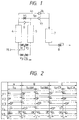
- a reference numeral 15 represents a raw material (compressed air) supply source
- reference numerals 4 and 5 designate first and second adsorption towers in which an adsorbent is charged.
- a reference numeral 7 denotes a buffer reservoir into which thickened gas is to be introduced.
- reference symbols V1, V2, V3, V4 and V5 represent valves respectively
- reference symbols V6 and V7 designate back-flow check valves.
- a reference numeral 9 denotes an orifice which functions to limit thickened oxygen gas which is supplied to desorb adsorbed nitrogen gas to a constant amount.
- Fig. 2 shows a sequence of time cycles of the oxygen gas thickening method according to the present invention.
- reference symbols A, B and C a represent preceding cycle, a unit operation (first cycle) and a unit cycle (second cycle) respectively
- reference symbols B1 and B2 designate desorption in the first desorption tower 4 at the first cycle and desorption in the second desorption tower 5 at the first cycle respectively
- the reference symbols C1 and C2 denote desorption in the first desorption tower 2 at a second cycle and adsorption in the second adsorption tower 3 at the second cycle respectively
- a reference symbol Ta represents an operation time for the unit operation in each of the adsorption tower.
- each of the preceding cycle (A), B1 and B2 at the first cycle, and C1 and C2 at the second cycle has an operation time of Ta.
- upper arrows and lower arrows on V1 through V5 valve operation lines indicate open valves (OP) and closed valves (CL) respectively.
- valve V1 is closed, the valve V2 is open, the valve V3 is open after it is closed for t second, the valve V4 is closed and the valve V5 is closed after it is open for t second as shown in Fig. 2. That is, the valve V1 is closed and the valve V2 is open at the preceding cycle (A), whereby compressed air is fed into the second adsorption tower 5 by way of the valve V2, and since the valves V3 and V4 are closed and the valve V5 is open for the 1 second, thickened oxygen gas accumulated in the fist adsorption tower 4 passes from the first adsorption tower 4 into the second adsorption tower 5, whereafter compressed air is successively adsorbed in the first adsorption tower 4.
- valve V3 When t second elapses after start of the preceding cycle (A), the valve V3 is opened from its closed condition and the valve V5 is closed from its open condition, whereby a desorbing gas is exhausted from the first adsorbing tower 4 through the valve V3.
- valve V1 is opened from its closed condition
- valve V2 is closed from its open condition
- valve V3 is closed from its open condition
- valve V4 is kept closed and opened t second later
- the valve V5 is kept open and closed t second later for the period of B1 as shown in Fig. 2.
- valve V3 Since the valve V3 is closed, the valve V4 is opened from its closed condition t second later and the valve V5 is open for the t second, thickened oxygen gas accumulated in the second adsorption tower 5 passes through the valve V5 into the first adsorption tower 4, thereby being effectively recovered.
- the valve V4 is opened from its closed condition and the valve V5 is closed from its open condition t second after start of the cycle B1, whereby the first adsorption tower proceeds to an adsorbing operation and the second adsorption tower proceeds to a desorbing operation.
- compressed air is fed as a raw material into the first adsorption tower 4 to adsorb nitrogen gas with the adsorbent, whereby thickened oxygen gas is fed into the buffer reservoir 7 thorough a flow path 4a.
- valve V1 is closed from its open condition and the valve V2 is opened from its closed condition, whereby the supply of the compressed air is switched from the first adsorption tower 4 to the second adsorption tower 5.
- the valve V3 remains closed at this time.
- the valve V4 which was open is closed, whereby both the valves V3 and V4 are set in closed conditions.
- the valve V5 is opened and closed after lapse of t second. Accordingly, thickened oxygen gas accumulated in the first adsorption tower 4 passes through the valve V5 into the second adsorption tower 5 and is recovered effectively for t second.
- valve V3 is opened and the valve V5 is closed t second later, whereby the raw material compressed air is send into the second adsorption tower 5 and the first absorption tower 4 starts a desorbing operation.
- the first cycle (B) terminates 2 ⁇ Ta second later as described above.
- the thickened oxygen gas is sent into the buffer reservoir 3.
- the oxygen gas thickening method according to the present invention is carried out with the apparatus having the configuration shown in Fig. 1 and at the time cycles shown in Fig. 2, and is characterized in that the time Ta (second) is reserved longer than that of the conventional method. Therefore, the oxygen gas thickening method according to the present invention is characterized in that it sends the compressed air into one of the adsorption towers, for example the first adsorption tower, for a time even after an adsorbing power of the adsorbent is saturated in the adsorption tower, whereby nitrogen is scarcely adsorbed and the compressed air is sent from the first adsorption tower into the buffer reservoir 7 to dilute high concentration oxygen gas which has already been sent. Accordingly, the oxygen gas thickening method according to the present invention makes it unnecessary to use an air bypass circuit, valves or valve switching operations in the circuit as shown in Fig. 1.
- Fig. 3 is a diagram showing variations of a concentration of product oxygen gas versus the adsorbing operation time Ta (second), and a reference symbol Tb in Fig. 3 represents an area at which the adsorbent is regenerated insufficiently and a reference symbol Tc designates an area at which the adsorbing capability of the adsorbent is saturated.
- a concentration of obtained oxygen gas is therefore determined by selection of the adsorbing operation time Ta. That is, prolonged Ta makes it possible to mix and dilute oxygen gas with raw material air free from adsorption obtained at the area Tc at which the adsorption capability of the adsorbent is saturated, and determine a mixing ratio of air from which nitrogen is not adsorbed dependently on a value of Tc, thereby obtaining oxygen gas at a correct concentration.
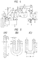
- Fig. 4 is a diagram showing an example of configuration of the oxygen thickening apparatus according to the present invention, wherein a reference numeral 1 represents a compact filter which eliminates pollutant fine particles from air, a reference numeral 2 designates a closed box containing an air compressor, a reference numeral 3 denotes a cooling pipe for cooling compressed air, a reference numeral 4A represents a first U-shaped adsorption tower, a reference numeral 5A designates a second U-shaped adsorption tower, reference symbols V6 and V7 denote back-flow check valves, a reference numeral 7 represents a buffer reservoir, a reference numeral 8 designates a pressure control valve with a pressure gauge, a reference numeral 9 denotes an air flowmeter with a flow control valve, a reference numeral 10 represents a flow rate limiting orifice for supplying oxygen gas as a desorbent regenerating gas, a reference numeral 11 designates a desorbed gas exhaust silencer and reference symbols V1 through V5 denotes
- the oxygen thickening apparatus which has the configuration described above eliminates the pollutant fine particles from raw material air with the compact filter 1, compresses the raw material air into high-pressure air with the air compressor 2, cools the high-pressure air with the cooling pipe 3 and supplies the high-pressure air into the first adsorption tower 4A or the second adsorption tower 5A, which prepares high-concentration oxygen by adsorbing nitrogen with an adsorbent and sends the high-concentration oxygen into the buffer reservoir 7 by way of the flow paths 4a and 5a. While the first adsorption tower 4A is operating to adsorb nitrogen gas to enhance a concentration of oxygen by switching the valves V1 through V5 at the time cycles shown in Fig. 2, the second adsorption tower 5A desorbs and exhausts nitrogen gas from the absorbent. These operations are performed alternately by switching the solenoid valves.
- the configuration shown in Fig. 4 of the oxygen gas thickening apparatus according to the present invention is fundamentally the same as that shown in Fig. 1 which is provided for description of the oxygen gas thickening method according to the present invention. Accordingly, the oxygen gas thickening apparatus according to the present invention shown in Fig. 4 provides thickened oxygen gas by switching the valves V1 through V5 on the basis of the time cycles shown in Fig. 2. Dependently on the selected time Ta, the oxygen gas thickening apparatus is capable of providing oxygen gas diluted to a desired concentration by utilizing air supplied when the adsorption capability of the adsorbent is saturated which has been described with reference to Fig. 3.
- the oxygen gas thickening apparatus shown in Fig. 4 is configured not only to carry out the oxygen gas thickening method according to the present invention which is described with reference to Fig. 1 but also have following characteristic which are different from those of the conventional apparatus.
- first and second adsorption towers have a form of a U pipe.
- a second characteristic lies in that the air compressor is accommodated in a closed box and suspended in the air with a configuration peculiar to the present invention, thereby preventing noise from being made due to vibrations and the like.
- exhausted desorbed gas is supplied into the closed box to suppress temperature rise as low as possible in the closed box, thereby lowering an operation cost of the air compressor.
- Fig. 5 is a diagram showing forms of adsorption towers; (A) being a conventional example, whereas (B) and (C) being adsorption towers according to the present invention.
- a reference symbol F1 represents a suction side filter
- a reference symbol F2 designates an exhaust side filter
- Table 1 shown below lists amounts of oxygen gas exhausted from the adsorption tower according to the present invention shown in (C) of Fig. 5 which has heights H and lengths L: Experiment 1 Experiment 2 Experiment 3 Experiment 4 (1) 25 cm 22.5 cm 20 cm 17.5 cm (2) 10 cm 15 cm 20 cm 25 cm (3) No gap in charged layer No gas in charged layer Slight gap in charged layer Slight gap in charged layer (4) 92% by volume 89% by volume 38% by volume 28% by volume
- line (1) lists a length L of a vertical section of the charged layer shown in (C) of Fig. 5
- line (2) lists a length W of a curved bottom section of the charged layer
- line (3) a visual observation result of the bottom section of the charged layer during operation
- line (4) lists a measured value of an oxygen concentration of exhausted oxygen gas.
- a U-shaped adsorption tower which is to be used in the oxygen gas thickening apparatus according to the present invention has a value of W which is smaller than a predetermined value.
- the oxygen gas thickening apparatus which uses the U-shaped adsorption towers according to the present invention is capable of providing oxygen gas stably for a time as long as 2000 hours.
- the oxygen gas thickening apparatus which uses the conventional straight pipe type adsorption towers allows a pressure and a concentration of exhaust oxygen gas to be apparently dropped in 500 hours. Accordingly, this oxygen gas thickening apparatus may allow the pressure and concentration drops after 100 hours, thereby requiring maintenance.
- the oxygen gas thickening apparatus according to the present invention is capable of providing oxygen gas stably for a time approximately 20 times as long as that the conventional apparatus as described above.
- the U-shaped adsorption towers so that the raw material feeding ports are disposed at upper locations in the oxygen gas thickening apparatus according to the present invention as shown in the drawing.
- the apparatus may be defective due to the filters and the similar members which are choked by the adsorbent like the oxygen gas thickening apparatus using the straight pipe type adsorption towers. It is therefore necessary to dispose the U-shaped adsorption towers so that the apparatus is free from the defect though slanted disposition of the adsorption towers poses no problem.
- the buffer reservoir may be a straight pipe type.
- the adsorption towers used in the oxygen gas thickening apparatus have a circular or elliptic sectional shape
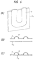
- these towers may be those which have a semicircular or semielliptic sectional shape as shown in Fig. 6.
- An adsorption tower which has such a semicircular or semielliptic sectional shape can be manufactured by press working a metal plate P1 so as to have a U shaped portion U as shown in (A) of Fig. 6 and cementing another plate P2 to the metal plate P1 in an airtight condition so as to form an adsorption tower which has a U-shaped sectional shape as that shown in (C) of Fig. 6. Accordingly, the U-shaped adsorption tower can be manufactured relatively easily.
- the adsorption tower may be formed by fixing the metal plate P1 directly to an inside surface of a wall which composes the casing.
- the adsorption tower can be manufactured more easily since the plate P1 having the U-shaped portion is fixed directly to the casing, thereby making no means to support the adsorption tower. According, this adsorption tower has a simple structure composed of a reduced number of parts, thereby allowing the oxygen gas thickening apparatus to be assembled easier and manufactured at a remarkably lower cost.
- an adsorption tower can be easily formed by erecting a plate corresponding to the plate P2 in the casing and fixing the plate P1 which has the U-shaped portion U to the plate disposed in place of the plate 2 so as to assure an airtight condition.
- the U-shaped adsorption tower which has the semicurcular sectional shape is more advantageous in its disposition and support than the U-shaped adsorption lower which has the circular sectional shape.
- the adsorption tower which has the semielliptic sectional shape can be manufactured in similar procedures and provides similar merits.
- Fig. 7 is a diagram showing a configuration of the air compressor enclosed in the closed box of the oxygen thickening apparatus according to the present invention.
- a reference numeral 51 represents a closed box made of sealing boards which are composed of laminated wood plates 15 mm thick and lead sheets 2 mm thick bonded to entire inside wall surfaces with elastic heat resisting adhesive sheets 1 mm thick
- a reference numeral 52 designates a piston compression type air compressor
- a reference numeral 53 denotes an electric motor
- a reference numeral 54 represents a suction nozzle of the air compressor
- a reference numeral 55 designates an air inlet pipe
- a reference numeral 56 denotes an air suction port of the compressor
- a reference numeral 57 represents a discharge nozzle
- a reference numeral 58 designates a compressed air outlet pipe composed of a heat resisting nylon tube
- a reference numeral 59 denotes a compressed air discharge port
- a reference numeral 60 represents a port to introduce desorbed gas from the ad
- the air compressor 52 and the motor 53 for driving the air compressor which are used in the oxygen gas thickening apparatus according to the present invention are fixed to the fixing stand 63 supported by the spring 65 in the closed box 51, whereby vibrations during an operation of the air compressor are absorbed nearly completely by the spring 65 and noise is scarcely transmitted outside the closed box.
- the vibration absorbing effect can be enhanced to prevent noise nearly completely by suspending the closed box 51 proper with a cord like member from a ceiling of the casing of the oxygen gas thickening apparatus in which the adsorption towers, the buffer reservoir, etc. are disposed.
- the cooling gas exhaust pipe 61 is disposed in the closed box 51 which accommodates the air compressor used in the oxygen gas thickening apparatus according to the present invention so that a gas exhausted from the exhaust pipe 61 prevents an internal temperature of the closed box 51 from being raised. Since the exhaust desorbed gas which is generally to be discharged outside is exhausted once into the closed box 51 for cooling its interior as shown Fig. 4 and then is discharged outside the closed box 51, the oxygen gas thickening apparatus is capable of cooling the interior of the closed box, or the air compressor, without using a cooling device which is separately disposed.
- the oxygen gas thickening apparatus is, as compared with an oxygen gas thickening apparatus which does not cool an air compressor, capable of more effectively preventing the air compressor from being troubled by seizure which is caused due to extreme temperature rise while the air compressor is operating.
- the oxygen gas thickening apparatus according to the present invention to select an air compressor which is capable of operating at high temperatures or specified for heat resistance, it is sufficient to select, for example, an air compressor which is used around an automobile engine.
- the oxygen gas thickening method according to the present invention makes it unnecessary to use a diluting auxiliary circuit, thereby making it possible to simplify a configuration of an oxygen gas thickening apparatus. Furthermore, the oxygen gas thickening method according to the present invention makes it possible to obtain oxygen gas at a desired concentration with simple valve switching operations.
- the oxygen gas thickening apparatus according to the present invention which uses the U-shaped adsorption towers requires no maintenance after a short term use, thereby being usable continuously for a long time and facilitating maintenance.
- the oxygen gas thickening apparatus according to the present invention uses the air compressor accommodated in the closed box to suppress emission of noise and more or less cools the interior of the closed box to prevent extreme temperature rise in the closed box, thereby being compatible with a generally available air compressor specified for heat resistance.
Landscapes
- Chemical & Material Sciences (AREA)
- Analytical Chemistry (AREA)
- Engineering & Computer Science (AREA)
- General Chemical & Material Sciences (AREA)
- Oil, Petroleum & Natural Gas (AREA)
- Chemical Kinetics & Catalysis (AREA)
- Organic Chemistry (AREA)
- Inorganic Chemistry (AREA)
- Separation Of Gases By Adsorption (AREA)
- Oxygen, Ozone, And Oxides In General (AREA)
Applications Claiming Priority (3)
| Application Number | Priority Date | Filing Date | Title |
|---|---|---|---|
| JP10051247A JPH11228107A (ja) | 1998-02-18 | 1998-02-18 | 酸素ガス濃縮方法および装置 |
| JP5124798 | 1998-02-18 | ||
| PCT/JP1999/000607 WO1999042403A1 (fr) | 1998-02-18 | 1999-02-12 | Condensateur de gaz oxygene et procede correspondant |
Publications (1)
| Publication Number | Publication Date |
|---|---|
| EP0978477A1 true EP0978477A1 (fr) | 2000-02-09 |
Family
ID=12881634
Family Applications (1)
| Application Number | Title | Priority Date | Filing Date |
|---|---|---|---|
| EP99903913A Withdrawn EP0978477A1 (fr) | 1998-02-18 | 1999-02-12 | Condensateur de gaz oxygene et procede correspondant |
Country Status (3)
| Country | Link |
|---|---|
| EP (1) | EP0978477A1 (fr) |
| JP (1) | JPH11228107A (fr) |
| WO (1) | WO1999042403A1 (fr) |
Cited By (11)
| Publication number | Priority date | Publication date | Assignee | Title |
|---|---|---|---|---|
| EP2613838A4 (fr) * | 2010-09-07 | 2014-05-21 | Inova Labs Inc | Système et méthode de gestion de la chaleur d'un concentrateur d'oxygène |
| US9440179B2 (en) | 2014-02-14 | 2016-09-13 | InovaLabs, LLC | Oxygen concentrator pump systems and methods |
| US9440036B2 (en) | 2012-10-12 | 2016-09-13 | InovaLabs, LLC | Method and systems for the delivery of oxygen enriched gas |
| US9440180B2 (en) | 2012-10-12 | 2016-09-13 | Inova Labs, Llc | Oxygen concentrator systems and methods |
| US9649465B2 (en) | 2007-09-06 | 2017-05-16 | Inova Labs, Inc. | Oxygen concentrator apparatus and method having variable operation modes |
| US9717876B2 (en) | 2012-10-12 | 2017-08-01 | Inova Labs, Inc. | Dual oxygen concentrator systems and methods |
| US20180369741A1 (en) * | 2017-06-27 | 2018-12-27 | Koninklijke Philips N.V. | Portable oxygen concentrator sieve bed |
| US20200368482A1 (en) * | 2019-05-22 | 2020-11-26 | Breathe Technologies, Inc. | O2 concentrator with sieve bed bypass and control method thereof |
| US11458274B2 (en) | 2016-05-03 | 2022-10-04 | Inova Labs, Inc. | Method and systems for the delivery of oxygen enriched gas |
| WO2022234238A1 (fr) * | 2021-05-04 | 2022-11-10 | Rober Limited | Dispositif de ventilation à pression positive |
| US20230414895A1 (en) * | 2021-01-27 | 2023-12-28 | Nanjing Yinuoji Medical Technology Co., Ltd. | Portable oxygen concentrator |
Families Citing this family (7)
| Publication number | Priority date | Publication date | Assignee | Title |
|---|---|---|---|---|
| KR100360836B1 (ko) * | 2000-08-09 | 2002-11-23 | 주식회사 옥서스 | 단탑형 산소농축기를 병렬배치한 산소발생장치 |
| JP4274300B2 (ja) * | 2000-09-06 | 2009-06-03 | 株式会社医器研 | 酸素濃縮装置及び酸素濃縮装置の運転制御方法 |
| US7294275B1 (en) * | 2005-05-04 | 2007-11-13 | The United States Of America, As Represented By The Secretary Of The Interior | Method of removing phosphorus from wastewater |
| KR101349493B1 (ko) * | 2011-12-28 | 2014-01-09 | 한국가스공사 | 순산소 연소식 기화장치 |
| JP5972727B2 (ja) * | 2012-09-18 | 2016-08-17 | ビィーゴ株式会社 | 酸素濃縮装置のカートリッジ |
| JP6568396B2 (ja) * | 2015-05-15 | 2019-08-28 | 株式会社日立産機システム | 気体分離装置、及び、それに用いる圧縮機冷却方法 |
| CN104971608A (zh) * | 2015-07-01 | 2015-10-14 | 汤荣康 | 一种协同法u型一体化脱硫脱硝除尘成套设备 |
Family Cites Families (5)
| Publication number | Priority date | Publication date | Assignee | Title |
|---|---|---|---|---|
| JPS6049127U (ja) * | 1983-09-07 | 1985-04-06 | 日立化成工業株式会社 | 酸素富化装置 |
| JPS6148406A (ja) * | 1984-08-15 | 1986-03-10 | Teijin Ltd | 酸素濃縮装置 |
| JPS61155204A (ja) * | 1984-12-28 | 1986-07-14 | Teijin Ltd | 酸素富化器 |
| JPS63242901A (ja) * | 1987-03-30 | 1988-10-07 | Teijin Ltd | 酸素濃縮装置 |
| JPH037916U (fr) * | 1989-06-07 | 1991-01-25 |
-
1998
- 1998-02-18 JP JP10051247A patent/JPH11228107A/ja active Pending
-
1999
- 1999-02-12 WO PCT/JP1999/000607 patent/WO1999042403A1/fr not_active Ceased
- 1999-02-12 EP EP99903913A patent/EP0978477A1/fr not_active Withdrawn
Non-Patent Citations (1)
| Title |
|---|
| See references of WO9942403A1 * |
Cited By (20)
| Publication number | Priority date | Publication date | Assignee | Title |
|---|---|---|---|---|
| US9649465B2 (en) | 2007-09-06 | 2017-05-16 | Inova Labs, Inc. | Oxygen concentrator apparatus and method having variable operation modes |
| US9649464B2 (en) | 2007-09-06 | 2017-05-16 | Inova Labs, Inc. | Oxygen concentrator apparatus and method having an ultrasonic detector |
| US9956370B2 (en) | 2007-09-06 | 2018-05-01 | Inova, Labs, LLC. | Oxygen concentrator apparatus and method having flow restricted coupling of the canisters |
| AU2011299224B2 (en) * | 2010-09-07 | 2015-11-19 | Inova Labs, Inc. | Oxygen concentrator heat management system and method |
| EP2613838A4 (fr) * | 2010-09-07 | 2014-05-21 | Inova Labs Inc | Système et méthode de gestion de la chaleur d'un concentrateur d'oxygène |
| US11364359B2 (en) | 2012-10-12 | 2022-06-21 | Inova Labs, Inc. | Method and systems for the delivery of oxygen enriched gas |
| US9440036B2 (en) | 2012-10-12 | 2016-09-13 | InovaLabs, LLC | Method and systems for the delivery of oxygen enriched gas |
| US9440180B2 (en) | 2012-10-12 | 2016-09-13 | Inova Labs, Llc | Oxygen concentrator systems and methods |
| US9717876B2 (en) | 2012-10-12 | 2017-08-01 | Inova Labs, Inc. | Dual oxygen concentrator systems and methods |
| US11684744B2 (en) | 2012-10-12 | 2023-06-27 | Inova Labs, Inc. | Method and systems for the delivery of oxygen enriched gas |
| US9440179B2 (en) | 2014-02-14 | 2016-09-13 | InovaLabs, LLC | Oxygen concentrator pump systems and methods |
| US11458274B2 (en) | 2016-05-03 | 2022-10-04 | Inova Labs, Inc. | Method and systems for the delivery of oxygen enriched gas |
| WO2019002075A1 (fr) * | 2017-06-27 | 2019-01-03 | Koninklijke Philips N.V. | Lit de tamis concentrateur d'oxygène portable |
| US20180369741A1 (en) * | 2017-06-27 | 2018-12-27 | Koninklijke Philips N.V. | Portable oxygen concentrator sieve bed |
| US20200368482A1 (en) * | 2019-05-22 | 2020-11-26 | Breathe Technologies, Inc. | O2 concentrator with sieve bed bypass and control method thereof |
| US11607519B2 (en) * | 2019-05-22 | 2023-03-21 | Breathe Technologies, Inc. | O2 concentrator with sieve bed bypass and control method thereof |
| US12102767B2 (en) | 2019-05-22 | 2024-10-01 | Breathe Technologies, Inc. | O2 concentrator with sieve bed bypass and control method thereof |
| US20230414895A1 (en) * | 2021-01-27 | 2023-12-28 | Nanjing Yinuoji Medical Technology Co., Ltd. | Portable oxygen concentrator |
| US12558511B2 (en) * | 2021-01-27 | 2026-02-24 | Intellifai Health, Inc. | Portable oxygen concentrator |
| WO2022234238A1 (fr) * | 2021-05-04 | 2022-11-10 | Rober Limited | Dispositif de ventilation à pression positive |
Also Published As
| Publication number | Publication date |
|---|---|
| WO1999042403A1 (fr) | 1999-08-26 |
| JPH11228107A (ja) | 1999-08-24 |
Similar Documents
| Publication | Publication Date | Title |
|---|---|---|
| EP0978477A1 (fr) | Condensateur de gaz oxygene et procede correspondant | |
| JP5604104B2 (ja) | 酸素を濃縮するシステムおよび方法 | |
| CN1315562C (zh) | 医用氧气浓缩器 | |
| KR100491684B1 (ko) | 압력순환흡착을 이용한 산소농축방법 및 장치 | |
| US20060137522A1 (en) | Oxygen concentrator for medical treatment | |
| CN102665812B (zh) | 氧浓缩装置 | |
| US11874026B2 (en) | Air conditioner and control method therefor | |
| CN101678189A (zh) | 氧浓缩装置 | |
| JP2008500890A (ja) | 気体濃縮方法およびその装置 | |
| CN117414674B (zh) | 一种制氧机温度控制系统及制氧机 | |
| WO2024047901A1 (fr) | Appareil de récupération de dioxyde de carbone et procédé de récupération de dioxyde de carbone | |
| KR101647017B1 (ko) | 응축 수분 배출 기능을 가지는 산소 농축 방법 및 장치 | |
| JP3974616B2 (ja) | 空調システムの酸素富化空気供給装置 | |
| CN100506586C (zh) | 具有供氧功能的汽车空车净化装置 | |
| KR100495973B1 (ko) | 자동차용 산소발생장치 | |
| JP3723478B2 (ja) | 濃縮酸素供給装置 | |
| KR100334723B1 (ko) | 단탑형 산소발생장치 | |
| KR100360836B1 (ko) | 단탑형 산소농축기를 병렬배치한 산소발생장치 | |
| KR200359140Y1 (ko) | 산소발생기용 조립모듈 | |
| KR100614849B1 (ko) | 기체농축기 및 그 밸브연결방법 | |
| JPH1119448A (ja) | 空気質活性装置 | |
| KR200217385Y1 (ko) | 단탑형 산소농축기를 병렬배치한 산소발생장치 | |
| JP2000107547A (ja) | 空気質活性装置 | |
| KR20240119716A (ko) | 공기 중의 산소 농도를 파악하고 단계별로 다른 농도의 산소를 발생시키는 가정용 산소 발생 시스템 및 그 방법 | |
| JPH1121107A (ja) | 空気質活性装置 |
Legal Events
| Date | Code | Title | Description |
|---|---|---|---|
| PUAI | Public reference made under article 153(3) epc to a published international application that has entered the european phase |
Free format text: ORIGINAL CODE: 0009012 |
|
| 17P | Request for examination filed |
Effective date: 19991117 |
|
| AK | Designated contracting states |
Kind code of ref document: A1 Designated state(s): DE ES FR GB IT SE |
|
| 18D | Application deemed to be withdrawn |
Effective date: 20020903 |
|
| STAA | Information on the status of an ep patent application or granted ep patent |
Free format text: STATUS: THE APPLICATION IS DEEMED TO BE WITHDRAWN |
|
| R18D | Application deemed to be withdrawn (corrected) |
Effective date: 20020903 |