EP0978619A2 - Profilé isolant - Google Patents
Profilé isolant Download PDFInfo
- Publication number
- EP0978619A2 EP0978619A2 EP99115054A EP99115054A EP0978619A2 EP 0978619 A2 EP0978619 A2 EP 0978619A2 EP 99115054 A EP99115054 A EP 99115054A EP 99115054 A EP99115054 A EP 99115054A EP 0978619 A2 EP0978619 A2 EP 0978619A2
- Authority
- EP
- European Patent Office
- Prior art keywords
- insulation strip
- insulation
- strip according
- frame structure
- insulating material
- Prior art date
- Legal status (The legal status is an assumption and is not a legal conclusion. Google has not performed a legal analysis and makes no representation as to the accuracy of the status listed.)
- Granted
Links
- 239000011810 insulating material Substances 0.000 claims abstract description 56
- 229910052751 metal Inorganic materials 0.000 claims abstract description 24
- 239000002184 metal Substances 0.000 claims abstract description 24
- 239000004033 plastic Substances 0.000 claims abstract description 11
- 229920003023 plastic Polymers 0.000 claims abstract description 11
- 238000009413 insulation Methods 0.000 claims description 159
- 239000012774 insulation material Substances 0.000 claims description 44
- 239000000463 material Substances 0.000 claims description 23
- 239000002131 composite material Substances 0.000 claims description 8
- -1 Polypropylene Polymers 0.000 claims description 6
- 238000004026 adhesive bonding Methods 0.000 claims description 5
- 239000004952 Polyamide Substances 0.000 claims description 2
- 239000004698 Polyethylene Substances 0.000 claims description 2
- 239000004743 Polypropylene Substances 0.000 claims description 2
- 239000004793 Polystyrene Substances 0.000 claims description 2
- 229920002647 polyamide Polymers 0.000 claims description 2
- 229920000573 polyethylene Polymers 0.000 claims description 2
- 229920000139 polyethylene terephthalate Polymers 0.000 claims description 2
- 239000005020 polyethylene terephthalate Substances 0.000 claims description 2
- 229920001155 polypropylene Polymers 0.000 claims description 2
- 229920002223 polystyrene Polymers 0.000 claims description 2
- 229920002635 polyurethane Polymers 0.000 claims description 2
- 239000004814 polyurethane Substances 0.000 claims description 2
- XECAHXYUAAWDEL-UHFFFAOYSA-N acrylonitrile butadiene styrene Chemical compound C=CC=C.C=CC#N.C=CC1=CC=CC=C1 XECAHXYUAAWDEL-UHFFFAOYSA-N 0.000 claims 1
- 239000004676 acrylonitrile butadiene styrene Substances 0.000 claims 1
- 229920000122 acrylonitrile butadiene styrene Polymers 0.000 claims 1
- 239000006261 foam material Substances 0.000 description 10
- 229910052782 aluminium Inorganic materials 0.000 description 9
- XAGFODPZIPBFFR-UHFFFAOYSA-N aluminium Chemical compound [Al] XAGFODPZIPBFFR-UHFFFAOYSA-N 0.000 description 9
- 239000006260 foam Substances 0.000 description 9
- 238000010276 construction Methods 0.000 description 8
- 238000005187 foaming Methods 0.000 description 6
- 238000004519 manufacturing process Methods 0.000 description 6
- 230000009467 reduction Effects 0.000 description 6
- 230000008901 benefit Effects 0.000 description 4
- 230000015572 biosynthetic process Effects 0.000 description 4
- 230000005855 radiation Effects 0.000 description 4
- 239000000853 adhesive Substances 0.000 description 3
- 230000001070 adhesive effect Effects 0.000 description 3
- 238000004873 anchoring Methods 0.000 description 3
- 238000000926 separation method Methods 0.000 description 2
- 230000006641 stabilisation Effects 0.000 description 2
- 238000011105 stabilization Methods 0.000 description 2
- 230000000087 stabilizing effect Effects 0.000 description 2
- 241000397426 Centroberyx lineatus Species 0.000 description 1
- 230000004913 activation Effects 0.000 description 1
- 230000004888 barrier function Effects 0.000 description 1
- 230000006872 improvement Effects 0.000 description 1
- 239000007924 injection Substances 0.000 description 1
- 238000002347 injection Methods 0.000 description 1
- 230000003993 interaction Effects 0.000 description 1
- 230000002452 interceptive effect Effects 0.000 description 1
- 239000013067 intermediate product Substances 0.000 description 1
- 238000002955 isolation Methods 0.000 description 1
- 239000000047 product Substances 0.000 description 1
- 230000002787 reinforcement Effects 0.000 description 1
- 230000003014 reinforcing effect Effects 0.000 description 1
- 230000003068 static effect Effects 0.000 description 1
- 238000010792 warming Methods 0.000 description 1
Images




Classifications
-
- E—FIXED CONSTRUCTIONS
- E06—DOORS, WINDOWS, SHUTTERS, OR ROLLER BLINDS IN GENERAL; LADDERS
- E06B—FIXED OR MOVABLE CLOSURES FOR OPENINGS IN BUILDINGS, VEHICLES, FENCES OR LIKE ENCLOSURES IN GENERAL, e.g. DOORS, WINDOWS, BLINDS, GATES
- E06B3/00—Window sashes, door leaves, or like elements for closing wall or like openings; Layout of fixed or moving closures, e.g. windows in wall or like openings; Features of rigidly-mounted outer frames relating to the mounting of wing frames
- E06B3/04—Wing frames not characterised by the manner of movement
- E06B3/263—Frames with special provision for insulation
- E06B3/2632—Frames with special provision for insulation with arrangements reducing the heat transmission, other than an interruption in a metal section
-
- E—FIXED CONSTRUCTIONS
- E06—DOORS, WINDOWS, SHUTTERS, OR ROLLER BLINDS IN GENERAL; LADDERS
- E06B—FIXED OR MOVABLE CLOSURES FOR OPENINGS IN BUILDINGS, VEHICLES, FENCES OR LIKE ENCLOSURES IN GENERAL, e.g. DOORS, WINDOWS, BLINDS, GATES
- E06B3/00—Window sashes, door leaves, or like elements for closing wall or like openings; Layout of fixed or moving closures, e.g. windows in wall or like openings; Features of rigidly-mounted outer frames relating to the mounting of wing frames
- E06B3/04—Wing frames not characterised by the manner of movement
- E06B3/263—Frames with special provision for insulation
- E06B3/2632—Frames with special provision for insulation with arrangements reducing the heat transmission, other than an interruption in a metal section
- E06B2003/26325—Frames with special provision for insulation with arrangements reducing the heat transmission, other than an interruption in a metal section the convection or radiation in a hollow space being reduced, e.g. by subdividing the hollow space
- E06B2003/26329—Frames with special provision for insulation with arrangements reducing the heat transmission, other than an interruption in a metal section the convection or radiation in a hollow space being reduced, e.g. by subdividing the hollow space the insulating strips between the metal sections being interconnected
-
- E—FIXED CONSTRUCTIONS
- E06—DOORS, WINDOWS, SHUTTERS, OR ROLLER BLINDS IN GENERAL; LADDERS
- E06B—FIXED OR MOVABLE CLOSURES FOR OPENINGS IN BUILDINGS, VEHICLES, FENCES OR LIKE ENCLOSURES IN GENERAL, e.g. DOORS, WINDOWS, BLINDS, GATES
- E06B3/00—Window sashes, door leaves, or like elements for closing wall or like openings; Layout of fixed or moving closures, e.g. windows in wall or like openings; Features of rigidly-mounted outer frames relating to the mounting of wing frames
- E06B3/04—Wing frames not characterised by the manner of movement
- E06B3/263—Frames with special provision for insulation
- E06B3/2632—Frames with special provision for insulation with arrangements reducing the heat transmission, other than an interruption in a metal section
- E06B2003/26325—Frames with special provision for insulation with arrangements reducing the heat transmission, other than an interruption in a metal section the convection or radiation in a hollow space being reduced, e.g. by subdividing the hollow space
- E06B2003/2633—Frames with special provision for insulation with arrangements reducing the heat transmission, other than an interruption in a metal section the convection or radiation in a hollow space being reduced, e.g. by subdividing the hollow space the insulating strips between the metal sections having ribs extending into the hollow space
-
- E—FIXED CONSTRUCTIONS
- E06—DOORS, WINDOWS, SHUTTERS, OR ROLLER BLINDS IN GENERAL; LADDERS
- E06B—FIXED OR MOVABLE CLOSURES FOR OPENINGS IN BUILDINGS, VEHICLES, FENCES OR LIKE ENCLOSURES IN GENERAL, e.g. DOORS, WINDOWS, BLINDS, GATES
- E06B3/00—Window sashes, door leaves, or like elements for closing wall or like openings; Layout of fixed or moving closures, e.g. windows in wall or like openings; Features of rigidly-mounted outer frames relating to the mounting of wing frames
- E06B3/04—Wing frames not characterised by the manner of movement
- E06B3/263—Frames with special provision for insulation
- E06B3/2632—Frames with special provision for insulation with arrangements reducing the heat transmission, other than an interruption in a metal section
- E06B2003/26332—Arrangements reducing the heat transfer in the glazing rabbet or the space between the wing and the casing frame
-
- E—FIXED CONSTRUCTIONS
- E06—DOORS, WINDOWS, SHUTTERS, OR ROLLER BLINDS IN GENERAL; LADDERS
- E06B—FIXED OR MOVABLE CLOSURES FOR OPENINGS IN BUILDINGS, VEHICLES, FENCES OR LIKE ENCLOSURES IN GENERAL, e.g. DOORS, WINDOWS, BLINDS, GATES
- E06B3/00—Window sashes, door leaves, or like elements for closing wall or like openings; Layout of fixed or moving closures, e.g. windows in wall or like openings; Features of rigidly-mounted outer frames relating to the mounting of wing frames
- E06B3/04—Wing frames not characterised by the manner of movement
- E06B3/263—Frames with special provision for insulation
- E06B2003/26349—Details of insulating strips
- E06B2003/2635—Specific form characteristics
- E06B2003/26352—Specific form characteristics hollow
- E06B2003/26354—Specific form characteristics hollow filled
-
- E—FIXED CONSTRUCTIONS
- E06—DOORS, WINDOWS, SHUTTERS, OR ROLLER BLINDS IN GENERAL; LADDERS
- E06B—FIXED OR MOVABLE CLOSURES FOR OPENINGS IN BUILDINGS, VEHICLES, FENCES OR LIKE ENCLOSURES IN GENERAL, e.g. DOORS, WINDOWS, BLINDS, GATES
- E06B3/00—Window sashes, door leaves, or like elements for closing wall or like openings; Layout of fixed or moving closures, e.g. windows in wall or like openings; Features of rigidly-mounted outer frames relating to the mounting of wing frames
- E06B3/04—Wing frames not characterised by the manner of movement
- E06B3/263—Frames with special provision for insulation
- E06B2003/26349—Details of insulating strips
- E06B2003/2635—Specific form characteristics
- E06B2003/26359—Specific form characteristics making flush mounting with neighbouring metal section members possible
-
- E—FIXED CONSTRUCTIONS
- E06—DOORS, WINDOWS, SHUTTERS, OR ROLLER BLINDS IN GENERAL; LADDERS
- E06B—FIXED OR MOVABLE CLOSURES FOR OPENINGS IN BUILDINGS, VEHICLES, FENCES OR LIKE ENCLOSURES IN GENERAL, e.g. DOORS, WINDOWS, BLINDS, GATES
- E06B3/00—Window sashes, door leaves, or like elements for closing wall or like openings; Layout of fixed or moving closures, e.g. windows in wall or like openings; Features of rigidly-mounted outer frames relating to the mounting of wing frames
- E06B3/04—Wing frames not characterised by the manner of movement
- E06B3/263—Frames with special provision for insulation
- E06B2003/26349—Details of insulating strips
- E06B2003/2635—Specific form characteristics
- E06B2003/26361—Openings, incisions or indents
-
- E—FIXED CONSTRUCTIONS
- E06—DOORS, WINDOWS, SHUTTERS, OR ROLLER BLINDS IN GENERAL; LADDERS
- E06B—FIXED OR MOVABLE CLOSURES FOR OPENINGS IN BUILDINGS, VEHICLES, FENCES OR LIKE ENCLOSURES IN GENERAL, e.g. DOORS, WINDOWS, BLINDS, GATES
- E06B3/00—Window sashes, door leaves, or like elements for closing wall or like openings; Layout of fixed or moving closures, e.g. windows in wall or like openings; Features of rigidly-mounted outer frames relating to the mounting of wing frames
- E06B3/04—Wing frames not characterised by the manner of movement
- E06B3/263—Frames with special provision for insulation
- E06B2003/26349—Details of insulating strips
- E06B2003/26369—Specific material characteristics
- E06B2003/26374—Specific material characteristics with parts of differing nature
-
- E—FIXED CONSTRUCTIONS
- E06—DOORS, WINDOWS, SHUTTERS, OR ROLLER BLINDS IN GENERAL; LADDERS
- E06B—FIXED OR MOVABLE CLOSURES FOR OPENINGS IN BUILDINGS, VEHICLES, FENCES OR LIKE ENCLOSURES IN GENERAL, e.g. DOORS, WINDOWS, BLINDS, GATES
- E06B3/00—Window sashes, door leaves, or like elements for closing wall or like openings; Layout of fixed or moving closures, e.g. windows in wall or like openings; Features of rigidly-mounted outer frames relating to the mounting of wing frames
- E06B3/04—Wing frames not characterised by the manner of movement
- E06B3/263—Frames with special provision for insulation
- E06B2003/26349—Details of insulating strips
- E06B2003/26369—Specific material characteristics
- E06B2003/26378—Specific material characteristics comprising foam
Definitions
- the present invention relates to an insulation strip Plastic for a composite profi with the characteristics of The preamble of claim 1.
- Usual insulation strips are used for the formation of frames in the Range of windows, doors and facades used. in the Individual is here for the lowest possible heat conduction between the outward and the inward Areas of a frame. This will do so ensures that for reasons of strength necessarily used through metal profiles Plastic strips are connected together at their Outer contour are equipped with connection profiles, for example with a dovetail, a hammer head or the like, so that they are in a respective holding contour of a metal profile can be inserted and in one direction perpendicular to its longitudinal extent in the holding contour are anchored. Thus, such plastic insulation strips ensure which serve to connect at least two metal profiles, for a thermal separation of the inside and the back exterior metal profiles.
- WO 97/09504 is a generic insulation strip, the is inserted between two metal profiles to fulfill known requirements.
- the Insulation strip two essentially parallel boundary walls that form a cavity between them.
- the Boundary walls are over at least one crossbar interconnected so that the cavity inside the Insulation strip in several, in the longitudinal direction of the insulation strip hollow chambers arranged one behind the other is divided.
- Connection profiles is the insulation strip in grooves from Metal profiles of a composite profile used.
- the thickness and the width of the boundary walls and the size of the Insulation strip is dimensioned so that the heat conduction between the inside and the metal profiles arranged outside if possible is kept low.
- a thermally insulated composite profile with two metal profiles via engaging with projections in grooves of the metal profiles multi-part insulating webs are connected to each other is in described in DE 42 38 750.
- the isolating bridge is off two parts, each with a different thickness composed and serves for thermal separation of the outer and inner metal profiles.
- the multi-part structure this known insulating strip, however, on the one hand a comparatively high production cost and is on the other hand, complex to use.
- From DE-A-3 342 700 is a thermally insulated profile body known, with the elongated, profiled insulating strips over edge folds attached at their end areas in Engage grooves in aluminum profile rails.
- Such Insulating strip has an open cross-sectional contour, whereby in combination with an aluminum profile rail Can form cavity. There is in the area of Interfering game between the insulating strip and the aluminum profile rail. To one for each Satisfactory connection or anchoring between the aluminum profile and the insulating strip create is a stabilization of the nested Items required.
- Aluminum profile rail can be activated by the supply of heat and foamable intermediate product in the connection area between the profile elements and in the of the insulating strip cavity formed with the aluminum profile rail brought in.
- the primary product is the hardening of the aluminum profile rail existing heat is used, so that a positive Connection of the insulating strip with the aluminum profile the foaming material takes place.
- the invention has for its object an insulation strip for Propose use in a composite profile that is high Has thermal insulation and at the same time sufficient Offers stability.
- the invention is based on the Geanke, an insulation strip To design plastic for a composite profile so that the Walls of the frame structure are kept thin.
- the heat flow through the insulation strip depends heavily on the thickness of the walls, so that this results in a reduction in the heat flow and can achieve an improvement in the insulation properties.
- thermal insulation material with at least part of the Frame structure is connected, in addition the Thermal insulation can improve. Est the combination of these two measures, optimizing the wall thickness of the Frame structure, and the additional provision of thermal insulation material optimizes the insulation strip Plastic in terms of insulation properties.
- Part of the frame structure of the insulation strip is thin-walled designed.
- an area has a wall thickness between 0.3 and 1.2 mm. This wall thickness in the specified area ensures a stable construction the insulation strip, while at the same time being proportionate low heat conduction over the walls is achieved.
- Insulating material on the frame structure attached that part of the mechanical stress on the insulation strip acts on the heat-insulating material is recorded. This enables the frame structure with regard to low heat conduction optimize, as this achieves the required strength is made by using the heat insulating material to hold the Contributes forces.
- connection profiles are preferably the Holding contour of the corresponding metal profile adjusted so that these form-fitting and secure in the metal profile are attachable.
- the Frame structure of the insulation strip at least one longitudinal wall and at least two crossbars.
- the frame structure out at least one longitudinal wall and at least two cross bars is built up, it is simple by appropriate Arrangement of the longitudinal walls and crossbars possible, the required Strength of the insulation strip over the each To achieve a customized profile.
- Longitudinal walls" of the bar become those areas understood, which is in the direction of a longitudinal extension of the Extend bar and the substantially parallel to Are heat flow direction.
- crossbars correspondingly those areas of the framework structure of the Insulation strip understood, which is in a transverse direction of the Extend insulation strip and essentially transverse to Are heat flow direction.
- the Frame structure of the insulation strip from at least one long wall constructed, at the end of which a crossbar is provided and is connected to the longitudinal wall. Covers the frame structure exactly one longitudinal wall, so this arrangement is a Double T-profile formed, the good mechanical Has strength properties.
- the frame structure of the insulating strip is preferably made of at least two longitudinal walls and at least two cross bars constructed, which are arranged so that they have at least one Limit cavity. This creates a hollow profile educated.
- This resulting hollow chamber has one closed cross-sectional shape with in the connection areas of the longitudinal walls and crossbars merging Inner walls. Be more than two crossbars provided, the insulation strip can be divided into several arranged hollow chambers are divided. Forming the Insulation strip with the formation of a hollow chamber is insofar advantageous as a closed cross-sectional shape on the one hand are both sufficiently rigid to withstand mechanical loads to be able to record, and on the other hand by the Air gap formed in the cavities, one Reduction of heat conduction through the bar is achieved.
- the longitudinal walls in are arranged substantially parallel to each other and / or the crosspieces are essentially at right angles from the Extend longitudinal walls.
- This arrangement results in at least two crossbars and two longitudinal walls one in essential rectangular cross-sectional contour of the Hollow chamber (s), which are also particularly stable Construction of the bar ensures that the respective Cross bar as a stabilizing bar between the longitudinal walls works.
- the crossbars are also in this way perpendicular to the direction of heat flow, which is essentially runs along the longitudinal walls, in the insulation strip aligned so that an additional heat conduction over the Crossbars is effectively counteracted.
- the insulating strip according to the invention is preferably made of Plastic and has a one-piece (integral) Frame profile on.
- the Insulation strip can be designed as a one-piece component that on the one hand with little effort and on the other hand is easy to manufacture.
- the Frame structure of the insulation strip from several individual Components assembled. This means an advantage because Standard elements can be used to create the Form frame structure. Merging the Frame structure from the individual components can according to preferred embodiments by gluing, over a positive connection or a clamp connection happen.
- the entire frame structure be uniform Has thickness of the walls.
- This thickness is in the range between 0.3 mm and 1.2 mm, preferably in the range between 0.5 mm and 1.0 mm. In this preferred range is Strength of the insulation strip ensured and a tolerable heat conduction available. The one over the bar flowing heat energy is u. a. through the thickness and the Width of the walls of the frame structure is affected. In this regard the smallest possible wall thickness should be aimed for, but without to neglect the necessary strength properties.
- the bar is a thickness S3 of the range of Frame structure that is adjacent to the insulating material, compared to the thickness of the remaining areas of the Reduced frame structure.
- S3 is in the Range from 0.15 x S1 to 0.95 x S1.
- thermal insulation material in at least one of the hollow chambers.
- the introduction of the heat-insulating or heat-insulating material into the space designed between the longitudinal walls and crosspieces allows a simple and effective way to reduce the heat conduction via the strip compared to a strip without additional insulation material, in which the insulation takes place via air in the corresponding cavities .
- an insulation strip with several neighboring hollow chambers of which at least one is filled with the heat insulating material.
- this multi-chamber hollow profile which is both with insulating material can have filled as well as air-filled chambers different variants conceivable, for example two adjacent hollow chambers, each with or without Insulation material are equipped and / or neighboring Hollow chambers, each alternately filled with insulating material or are not filled.
- a particularly simple and stable design of the insulation strip results in a preferred embodiment in which the bar has a length of 30 mm to 100 mm, preferably 40 mm to 70 mm, and a width of 10 mm to 100 mm, preferably 15 mm to 80 mm or 20 mm to 50 mm.
- This embodiment offers insulation strips that Show hollow chambers, advantages for a uniform Subdivision of the bar into hollow chambers and thus for one good thermal insulation if the hollow chamber is 5 mm high 30 mm, preferably 5 mm to 15 mm, or a height of 5 mm up to 60 mm, preferably 10 mm to 40 mm.
- This Dimensions of the hollow chamber ensure the design of a sufficiently large filling volume for the Insulation material to effectively reduce heat conduction to achieve.
- the thermal insulation material to the Frame structure glued, clamped or with a positive connection connected to it.
- a positive connection such as. B. undercut tongue and groove connections, gears or Similar, is the thermal insulation material on the insulation strip additionally secured against slipping or loosening. The Connection is therefore extremely stable. This is particularly true the places where mechanical stress is advantageous the thermal insulation material is to be transferred.
- the foam-like Material ensures that the respective hollow chamber completely filled in and thus the largest possible volume insulation material is introduced into the bar.
- the foam is preferably simply injected into the cavity and then foams in the hollow chamber.
- the Reacting is glued to the hollow chamber wall.
- foam-like material made of polyurethane, polystyrene or the like exists. These materials can be easily after injection, foam and are in the hollow chamber moreover, comparatively poor heat conduction, so that the principle according to the invention is thereby particularly good can be realized.
- Insulating material is designed in a strip shape. Thereby it is possible to lightly strip the insulation material into the Insert hollow chamber (s) and possibly also for stiffening the last construction in the respective hollow chamber to stick. In addition, by strip-shaped Material certain insulation properties can be achieved, by combining different strips of insulation material become.
- the use has proven to be useful for the plastic insulation strip of polypropylene, polyethylene, polyamide, acrynitrile-butadiene-styrene or polyethylene terephthalate as advantageous.
- This Materials can be reinforced with appropriate reinforcement and / or Reinforcing elements are provided to ensure the stability of the To increase insulation strip further.
- the use of this Materials allows the production of very temperature-resistant and stable strips.
- the insulation strip recesses in at least one of the longitudinal walls.
- Recesses inhibit the heat flow through the bar additionally. This improves insulation properties achieved.
- These recesses can have a wide variety of geometries have, for example rectangular are conceivable Cutouts, circular cutouts, triangular Recesses or the like. It is still possible and even more preferred that multiple rows of Cutouts are arranged, these cutouts will be in the rows are offset from each other, the heat flow additionally reduced via the bar since there is no straight line Connection in the longitudinal direction of the bar in the frame structure consists.
- the heat-insulating material is preferably one appropriate requirements placed on the insulation strip so that it protrudes from the frame profile. For one thing, it will the surface of the bar enlarges, resulting in a larger one Radiation area and thus a lower heat flow leads between inner profile and outer profile. This improves on the one hand the insulation properties of the insulation strip. On the other hand can target certain geometries of the bar through the Insulation material can be realized.
- the projecting one is Insulation material between projections of the frame structure, which as Recordings seem appropriate. These projections serve mainly to ensure that the insulating material is securely attached Hold place so that it is less susceptible to Is slipping or loosening.
- This insulation material can on the one hand an insulation material of the insulation strip according to the invention be opposite, also to reinforce the frame structure serves mechanical load, on the other hand this can thermal insulation material, however, additionally on the Be attached to the outside of the insulation strip and exclusively Isolation and insulation purposes.
- the insulation strip according to the invention has Plastic has an integral cross-sectional shape, whereby thin-walled longitudinal walls and crossbars of the insulation strip integral are interconnected.
- a wall thickness of Longitudinal wall in a range between 0.3 mm and 1.2 mm.
- the longitudinal walls and crossbars are in such a way with each other connected that these limit at least one hollow chamber, so that a hollow profile is formed.
- the hollow chamber has one closed cross-sectional shape with in the connection areas of the longitudinal walls and crossbars merging Inner walls.
- the crossbars are between the Longitudinal walls are provided, creating a between two longitudinal walls formed cavity inside the insulation strip in or in several, along the length of the bar hollow chamber (s) arranged one behind the other is divided.
- a heat-insulating material is filled into the hollow chamber designed in this way.
- the introduction of the heat-insulating or heat-insulating material into the space designed between the longitudinal walls and crosspieces allows a simple and effective way of reducing the heat conduction via the strip.
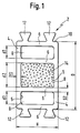
- FIG. 1 is a cross-sectional view Insulation strip 2 according to the invention made of plastic in a first Embodiment shown.
- the insulation strip 2 two substantially parallel and in Distance from each other arranged longitudinal walls 4, which between form a cavity.
- the two longitudinal walls 4 are connected by a total of four crosspieces 6, wherein the crosspieces 6 are essentially at right angles to the Cavity-facing inside 5 of the longitudinal walls 4 arranged are.
- the transverse webs 6, as in FIG. 1 can be seen in one piece with the longitudinal walls 4 of the insulation strip 2 trained.
- crossbars 6 By being perpendicular to the longitudinal walls 4 extending crossbars 6 is the cavity inside the Insulation strip 2 in several, in the longitudinal direction of the longitudinal walls 4th the insulating strip 2 hollow chambers 8 arranged one behind the other divided. In this way it can be seen that the bar 2 is designed as a hollow profile.
- the crossbars 6 and the Longitudinal walls 4 together form the frame structure 7 of the Insulation strip.
- connection profiles 12 There are several on an outer contour 10 of the strip 2 Connection profiles 12 provided. These are shown in the Case as a widening, so-called Dovetail run and exhibit two of which in Fig. 1 top and bottom crossbar 6 to the outside inclined sides, so that a total widened foot or head arises.
- the insulation strip 2 shown in one Holding contour of a (not shown) metal profile, the one has a complementarily shaped groove with undercuts, anchorable.
- the central, central hollow chamber 8 has a filling made of a heat-insulating material, in the present case a foam on. Because of the foam is the middle one Hollow chamber 8 completely filled. In the in Fig. 1st Hollow chambers 8 shown above and below, however, is not contain thermal insulation material.
- the length D of the insulation strip 2 is greater than a width H. Furthermore, in the drawing above and hollow chambers 8 arranged below have a lower height d1 than the middle hollow chamber 8 with a height d2. Thereby Different volumes of the hollow chambers 8 can be realized become.
- a thickness S1 of the longitudinal walls 4 corresponds to a thickness S2 of the crossbars 6.
- the bar 2 Due to the inventive design of the bar 2 as Multi-chamber hollow profile with thin-walled longitudinal walls 4 and Crosspieces 6 can conduct heat through the strip 2 be significantly reduced. In addition, the additional provision of the insulating foam material in one or more hollow chamber (s) through the heat conduction the bar 2 further reduced significantly.
- the foaming of the hollow chamber continues to cause Increase the mechanical strength of the construction by the filling material is part of the mechanical load records. This allows the wall thicknesses of the longitudinal walls can be further reduced.
- FIG. 2 In a cross-sectional view of a second embodiment of the insulating strip 2 according to the invention shown in FIG. 2, the aspect of absorbing mechanical stress through the filling material interacting with the frame structure becomes clear.
- This embodiment corresponds essentially to the embodiment shown in FIG. 1.
- the strip 2 is in the areas of reduced thickness S3 through the foam material 14 to increase the strength braced.
- Heat conduction by reducing the thickness of the longitudinal walls 4 additionally reduced.
- Foam material 14 additionally with the respective longitudinal walls 4 connected by an adhesive bond, which is an interaction the frame structure with the filling material guaranteed.
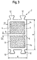
- Fig. 3 is shown as a third embodiment of the invention in cross section an insulation strip 2, the structure of which corresponds essentially to the insulation strip 2 shown in Fig. 1.
- the hollow profile of the strip 2 comprises a total of two hollow chambers 8.
- the two hollow chambers 8 are each completely foamed with the heat-insulating material 14.
- the entire hollow profile body of the strip 2 is filled with insulating material 14, which enables a very effective thermal insulation. Because all the walls of the frame structure adjoin a foamed area, the wall thicknesses of the frame structure S 1 and S 2 can be chosen to be very small, since part of the mechanical load is absorbed by the foam material, which thus stiffens the frame structure.
- the small wall thickness of the frame structure also leads to a reduction in heat conduction through the insulation strip.
- the stabilizing foam can also be glued to the frame structure. However, a sufficient hold between the frame structure and the insulation material is usually achieved without additional gluing, especially when using foam-like insulation material, which is first poured into an area of the insulation strip and then foamed.
- FIG fourth embodiment of the insulation strip 2 differs from that shown in Fig. 1 in essential in that fork-like connecting profiles 12 the outer contour 10 of the bar 2 are formed.
- those shown in FIG. 4 above and below Hollow chambers 8 opened and, in contrast to the previous embodiments no closed Cross-sectional contour.
- the middle hollow chamber 8 is here always filled with the insulating material 14, whereby the two outer hollow chambers 8, which are not complete have a closed cross-section (in the drawing above and below) optionally filled with an insulating material could be.
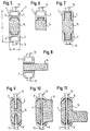
- Fig. 5 shows a fifth embodiment of the insulation strip according to the invention 2.
- the frame structure 7 from two individual components educated. These components each include crossbars 6 and Longitudinal walls 4.
- the connection of the two individual components happens over the insulating material 14. That Thermal insulation material 14 can either between the Frame structure 7 components glued or clamped be, with a positive connection between the Frame parts 7 and the heat-insulating material 14 for use can come. Such a connection is exemplified in Fig. 6 shown.
- the thermal insulation material is here with a provided undercut spring, the frame structure 7 with a corresponding undercut groove.
- the embodiment of the insulation strip 2 shown in FIG. 5 can but can also be made using the frame structure 7 is initially manufactured with three chambers, the middle chamber, which is then the thermal insulation material, preferably foam material, accommodates 14, initially wider is manufactured when the end width H of the insulation strip 2. After the foam material 14 has been introduced into the middle one Cavity and foaming are milled off the side walls. The foam material 14 thus takes over an essential part the mechanical load acting on the insulation strip 2.
- connection between Frame structure 7 and heat-insulating material 14 is next to it the aforementioned shape in the area of the connection between Frame structure and heat-insulating material possible through Application of adhesive material in addition to the connection consolidate.
- the shape, the connection in addition secures in the connection area between frame structure 7 and Foam material 14 can, as shown in Fig. 7, also from a Interlocking on the frame structure and a corresponding one There are teeth on the insulating material. This increases the liability between insulating material and Frame structure 7 and thus ensures a form-fitting Connection.
- connection profile 12 shown in FIGS. 5, 6 and 7 to the Holding contour of a metal profile is on both sides of the insulation strip 2 as one piece Swallowtail trained in a corresponding Cutout on a holding contour of a metal profile intervenes.
- Shapes according to the holding contour of the metal profile conceivable.
- FIGS. 5, 6 and 7 shown in FIGS Insulation strips have an interrupted frame structure 7. Because no direct connection through the Frame structure exists, and the heat flow only through that Insulating material takes place, the heat flow in the Insulation strip severely limited. Thus, good ones Thermal insulation properties achieved.
- FIG. 5 8 Another embodiment, that of FIG. 5 8 is shown.
- the insulation material 14 is here glued between two parts of the frame structure 7. in the Contrary to the previously shown embodiments, closes the thermal insulation material between the frame structure 7 is glued, but not flush with the frame structure 7 and in particular from the longitudinal walls 4, but is laterally extended.
- this can be advantageous because higher thermal insulation is achieved.
- the Heat exchange by radiation hampers, which also leads to Achieving good insulation properties is exploited.
- a Reduction of the convection space also ensures improved insulation properties.
- Figures 9, 10 and 11 show various aspects of another Embodiment of the present invention.
- the frame structure 7 from an im essentially continuous longitudinal wall 4 and two on their End arranged transverse webs 6 formed. These crossbars serve to absorb the insulating material and cause it Desired and required stabilization of the insulation strip.
- the insulating material 14 is on the side of the longitudinal wall on both Pages arranged, symmetrical in the case of Figure 9, in the case of Figures 10 and 11 asymmetrical.
- the one shown in Fig. 9 Longitudinal wall 4 has interruptions 13, which are in Fig. 10 and 11 longitudinal walls 4 not shown.
- connection profile 12 to the holding contour of a metal profile (not shown) each a dovetail that is centered on the outside the cross sections 6 is attached.
- the Interruptions in the longitudinal wall have the advantage that when Foaming the insulation material through the Recesses extends in the longitudinal wall and thus the two Areas of the insulation material on both sides of the longitudinal walls are formed from a single piece. This increases the mechanical stability of the insulation material.
- the insulating material is attached to the side of the longitudinal wall 4.
- This insulating material 14, for. B. foam material can either be glued to the frame structure 7, the in 9, 10 and 11 shown cross profiles an arcuate Have shape and thus hold the foam mass 14 in addition and secure against loosening in relation to the frame structure.
- the insulating material can also be similar to that in FIG. 5 described, introduced in that first a closed hollow profile is formed, in which the Foam material 14 is poured, and then the outer Longitudinal walls are milled away in order to achieve the final shape come, which is shown in Fig. 9.
- Figures 10 and 11 show Similar to FIG. 8, an insulation strip 2, in which at least one Part of the heat insulating material 14, which in connection with stands the frame structure 7, protrudes from this.
- This Projection of the insulating material 14 can over the entire length of the Insulation strip may be present, or only over partial areas. As mentioned above, it serves as far as there is space allow in the overall arrangement, the additional insulation by reducing the convection space and as Radiation barrier.
- the insulation strip 2 in one of those shown in FIGS. 9, 10 and 11 Embodiments offers good insulation and Thermal insulation properties because the frame structure is thin can be formed because the heat-insulating material 14 a Absorbs part of the mechanical load. Thin profiles ensure low heat conduction and therefore good Thermal insulation properties.
- FIGS. 12, 15, 16th and 17 are further embodiments of the present invention shown. These embodiments common that, as from the side views (Fig. 12, 15, 16th and 17) can be seen the insulation strip along its Cross-sections changing in the longitudinal direction.
- at least one of the longitudinal walls 4 of the Insulation strip 2 is provided with recesses 15, which to the Leads to cross-sectional changes. Otherwise these recesses reduce closed hollow profile of this embodiment additionally the heat flow.
- the longitudinal wall can only be in one limited area serve as a thermal bridge.
- the course of the Heat flow is indicated by an arrow Q in FIGS. 12, 15, 16 and 17 indicated.
- the recesses 15 in the longitudinal wall 4 of the Insulation strips can have different shapes (circle, rectangle, Triangle etc.).
- FIGS. 13 and 14 Cuts through the insulation strip according to FIG. 12 are shown in FIGS. 13 and 14.
- 13 corresponds to a section the position marked with A-A from FIG. 12, FIG. 14 a cut at the point marked B-B.
- the insulation strip additionally an area protruding from the main profile having.
- this is not absolutely necessary but a flush formation of the foam filling 14 in the Insulation strip 2, the cutouts in at least one of their Longitudinal walls 4 is conceivable and in Fig. 18th shown.
- FIGS. 19 and 20 Another essential feature is shown in FIGS. 19 and 20 shown.
- the illustrated embodiment of the invention is based on the embodiment shown in FIG. 2.
- Insulated material 18 attached to the insulation strip 2.
- this additional insulation material 18 is generally stuck on.
- a bracket 19 for this Additional insulation in the frame structure should be integrated in the form of projections that additionally increase the radiation area, as shown in Fig. 20, the additional insulation area without further guidance be glued on.
- Attaching one Holding structure 19 offers an additional security against slipping of the insulating material the advantage that Insulation material can also be clamped in this holding area can, or the holding area with the insulating material can form-fit connection.
- the essential aspect of the insulation strip according to the invention lies in that, since it was recognized that the thermal insulation material absorbs part of the mechanical load that Frame structure of the insulation strip may be thin-walled can or in some areas recesses or May have interruptions. This leads to the fact that Thermal insulation properties of the insulation strip can be improved without to forego mechanical strength properties have to.
- the frame structure of the insulation strip is not open certain embodiments limited, but all conceivable Frame structures can be combined with thermal insulation Material that is attached so that it is part of the absorbs mechanical stress.
Landscapes
- Physics & Mathematics (AREA)
- Thermal Sciences (AREA)
- Engineering & Computer Science (AREA)
- Civil Engineering (AREA)
- Structural Engineering (AREA)
- Building Environments (AREA)
- Refrigerator Housings (AREA)
- Wing Frames And Configurations (AREA)
- Insulation, Fastening Of Motor, Generator Windings (AREA)
- Laminated Bodies (AREA)
- Insulating Bodies (AREA)
- Body Structure For Vehicles (AREA)
Priority Applications (1)
| Application Number | Priority Date | Filing Date | Title |
|---|---|---|---|
| EP03005354A EP1318262B1 (fr) | 1998-08-05 | 1999-08-04 | Profilé isolant |
Applications Claiming Priority (2)
| Application Number | Priority Date | Filing Date | Title |
|---|---|---|---|
| DE19835439 | 1998-08-05 | ||
| DE19835439A DE19835439A1 (de) | 1998-08-05 | 1998-08-05 | Hohldämmleiste |
Related Child Applications (1)
| Application Number | Title | Priority Date | Filing Date |
|---|---|---|---|
| EP03005354A Division EP1318262B1 (fr) | 1998-08-05 | 1999-08-04 | Profilé isolant |
Publications (4)
| Publication Number | Publication Date |
|---|---|
| EP0978619A2 true EP0978619A2 (fr) | 2000-02-09 |
| EP0978619A3 EP0978619A3 (fr) | 2000-09-20 |
| EP0978619B1 EP0978619B1 (fr) | 2003-06-18 |
| EP0978619B9 EP0978619B9 (fr) | 2004-08-11 |
Family
ID=7876590
Family Applications (2)
| Application Number | Title | Priority Date | Filing Date |
|---|---|---|---|
| EP03005354A Expired - Lifetime EP1318262B1 (fr) | 1998-08-05 | 1999-08-04 | Profilé isolant |
| EP99115054A Expired - Lifetime EP0978619B9 (fr) | 1998-08-05 | 1999-08-04 | Profilé isolant |
Family Applications Before (1)
| Application Number | Title | Priority Date | Filing Date |
|---|---|---|---|
| EP03005354A Expired - Lifetime EP1318262B1 (fr) | 1998-08-05 | 1999-08-04 | Profilé isolant |
Country Status (3)
| Country | Link |
|---|---|
| EP (2) | EP1318262B1 (fr) |
| AT (2) | ATE243294T1 (fr) |
| DE (3) | DE19835439A1 (fr) |
Cited By (11)
| Publication number | Priority date | Publication date | Assignee | Title |
|---|---|---|---|---|
| EP1180574A2 (fr) | 2000-08-16 | 2002-02-20 | Harald Dr.-Ing. Schulz | Profilé isolant creux rempli d'une mousse plastique |
| EP1170454A3 (fr) * | 2000-07-08 | 2002-10-09 | Norsk Hydro A/S | Profilé composite calorifuge, notamment pour fenêtres, portes, façades et similaires |
| EP1347141A1 (fr) * | 2002-03-20 | 2003-09-24 | SCHÜCO International KG | Procédé de fabrication d'un profilé isolant et profilé isolant fabriqué selon ce procédé |
| EP1531228A1 (fr) | 2003-11-11 | 2005-05-18 | Technoform Caprano und Brunnhofer GmbH & Co. KG | Profilé composite |
| WO2008119535A1 (fr) * | 2007-04-02 | 2008-10-09 | Technoform Caprano Und Brunnhofer Gmbh & Co. Kg | Entretoise isolante sous forme d'échelle pour profilé composite pour éléments de fenêtres, de portes et de façades et profilé composite pour éléments de fenêtres, de portes et de façades |
| GB2464558A (en) * | 2008-10-25 | 2010-04-28 | Bowater Building Products Ltd | Window frame with thermal break |
| FR2940345A1 (fr) * | 2008-12-19 | 2010-06-25 | Ouest Alu | Menuiserie pour baie de batiment, et profils pour la confection d'une telle menuiserie |
| DE102013010336A1 (de) | 2012-06-20 | 2013-12-24 | Technoform Bautec Holding Gmbh | Verfahren zur einfachen Herstellung von dünnwandigen Dämmleisten mit stützendem, wärmedämmendem Material |
| DE102014103950A1 (de) | 2014-03-21 | 2015-09-24 | Heroal - Johann Henkenjohann Gmbh & Co. Kg | Isolierelement für Fassaden- oder Lichtdachkonstruktionen |
| EP3162531A1 (fr) | 2015-10-30 | 2017-05-03 | Technoform Tailored Solutions Holding GmbH | Procédé de fabrication de profilés en mousse et profils de mousse pouvant être obtenus par le procédé |
| CN110094137A (zh) * | 2019-03-15 | 2019-08-06 | 山西鑫铭格消防科技有限公司 | 一种复合材料节能门窗型材 |
Families Citing this family (4)
| Publication number | Priority date | Publication date | Assignee | Title |
|---|---|---|---|---|
| PL1510643T3 (pl) * | 2003-09-01 | 2018-06-29 | Forster Profilsysteme Ag | Profil i sposób wytwarzania profilu |
| DE102004038868A1 (de) * | 2004-08-10 | 2006-02-23 | Hydro Building Systems Gmbh | Wärmegedämmtes Profil für Fenster, Türen, Fassadenelemente und dergleichen |
| DE202007000004U1 (de) * | 2007-02-27 | 2008-04-10 | Henkenjohann, Johann | Fensterprofil |
| DE102009037851A1 (de) | 2009-08-18 | 2011-02-24 | Technoform Caprano Und Brunnhofer Gmbh & Co. Kg | Mehrteiliger Isolierkörper zur thermischen Trennung in Profilen für Fenster-, Türen- und Fassadenelemente, Profil für Fenster-, Türen- und Fassadenelemente sowie Herstellungsverfahren für den Isolierkörper und das Profil |
Citations (3)
| Publication number | Priority date | Publication date | Assignee | Title |
|---|---|---|---|---|
| DE3342700A1 (de) | 1983-07-06 | 1985-01-17 | Helmar Dr.Dr. 8530 Neustadt Nahr | Verfahren zur herstellung eines waermeisolierenden profilkoerpers |
| DE4238750A1 (de) | 1992-11-17 | 1994-05-26 | Wicona Bausysteme Gmbh | Wärmegedämmtes Verbundprofil |
| WO1997009504A1 (fr) | 1995-09-05 | 1997-03-13 | Norsk Hydro A.S | Profile composite utilise comme isolant thermique |
Family Cites Families (8)
| Publication number | Priority date | Publication date | Assignee | Title |
|---|---|---|---|---|
| DE2930689C2 (de) * | 1979-07-28 | 1984-10-18 | Friedl, Ekkehard, 5272 Wipperfürth | Verfahren zum Herstellen eines Verbundfensters |
| DE3227509A1 (de) * | 1982-07-23 | 1984-01-26 | Wilfried Dipl.-Ing. 7031 Nufringen Ensinger | Verbundprofil, insbesondere fuer rahmen von fenstern, tueren und fassadenelementen |
| DE4321702A1 (de) * | 1993-06-30 | 1995-01-19 | Hueck Eduard Gmbh Co Kg | Rahmen für ein Fenster, eine Tür oder Fassade |
| DE4427682C2 (de) * | 1994-08-04 | 1996-12-12 | Ensinger Gmbh & Co | Verbundprofil für Rahmen von Fenstern, Türen, Fassadenelementen u. dgl. |
| DE19513836A1 (de) * | 1995-04-12 | 1996-10-17 | Ekonal Bausysteme Gmbh & Co Kg | Fenster, Tür o. dgl. mit einem Blendrahmen und einem zugehörigen Flügelrahmen |
| DE29507046U1 (de) * | 1995-04-26 | 1996-08-22 | Hörmann KG Eckelhausen, 66625 Nohfelden | Gebäudeabschluß |
| DE29704201U1 (de) * | 1996-03-13 | 1997-06-26 | W. Hartmann & Co (Gmbh & Co), 20459 Hamburg | Wärmegedämmtes Verbundprofil |
| EP0906999B2 (fr) * | 1997-10-04 | 2008-05-28 | Albert Krämer | Ame isolante de profilés composites de cadres de fenêtre ou de porte |
-
1998
- 1998-08-05 DE DE19835439A patent/DE19835439A1/de not_active Ceased
-
1999
- 1999-08-04 AT AT99115054T patent/ATE243294T1/de not_active IP Right Cessation
- 1999-08-04 DE DE59905978T patent/DE59905978D1/de not_active Expired - Lifetime
- 1999-08-04 DE DE59915206T patent/DE59915206D1/de not_active Expired - Lifetime
- 1999-08-04 EP EP03005354A patent/EP1318262B1/fr not_active Expired - Lifetime
- 1999-08-04 AT AT03005354T patent/ATE483887T1/de active
- 1999-08-04 EP EP99115054A patent/EP0978619B9/fr not_active Expired - Lifetime
Patent Citations (3)
| Publication number | Priority date | Publication date | Assignee | Title |
|---|---|---|---|---|
| DE3342700A1 (de) | 1983-07-06 | 1985-01-17 | Helmar Dr.Dr. 8530 Neustadt Nahr | Verfahren zur herstellung eines waermeisolierenden profilkoerpers |
| DE4238750A1 (de) | 1992-11-17 | 1994-05-26 | Wicona Bausysteme Gmbh | Wärmegedämmtes Verbundprofil |
| WO1997009504A1 (fr) | 1995-09-05 | 1997-03-13 | Norsk Hydro A.S | Profile composite utilise comme isolant thermique |
Cited By (17)
| Publication number | Priority date | Publication date | Assignee | Title |
|---|---|---|---|---|
| EP1170454A3 (fr) * | 2000-07-08 | 2002-10-09 | Norsk Hydro A/S | Profilé composite calorifuge, notamment pour fenêtres, portes, façades et similaires |
| EP1980701A1 (fr) | 2000-07-08 | 2008-10-15 | Norsk Hydro A/S | Profilé composite isolé thermiquement en particulier pour fenêtres, portes, façades et analogues |
| EP1180574A2 (fr) | 2000-08-16 | 2002-02-20 | Harald Dr.-Ing. Schulz | Profilé isolant creux rempli d'une mousse plastique |
| EP1180574A3 (fr) * | 2000-08-16 | 2002-10-30 | Harald Dr.-Ing. Schulz | Profilé isolant creux rempli d'une mousse plastique |
| EP1347141A1 (fr) * | 2002-03-20 | 2003-09-24 | SCHÜCO International KG | Procédé de fabrication d'un profilé isolant et profilé isolant fabriqué selon ce procédé |
| EP1531228A1 (fr) | 2003-11-11 | 2005-05-18 | Technoform Caprano und Brunnhofer GmbH & Co. KG | Profilé composite |
| US7104019B2 (en) | 2003-11-11 | 2006-09-12 | Technoform Caprano Und Brunnhofer Gmbh & Co. Kg | Composite insulating profile |
| WO2008119535A1 (fr) * | 2007-04-02 | 2008-10-09 | Technoform Caprano Und Brunnhofer Gmbh & Co. Kg | Entretoise isolante sous forme d'échelle pour profilé composite pour éléments de fenêtres, de portes et de façades et profilé composite pour éléments de fenêtres, de portes et de façades |
| GB2464558A (en) * | 2008-10-25 | 2010-04-28 | Bowater Building Products Ltd | Window frame with thermal break |
| FR2940345A1 (fr) * | 2008-12-19 | 2010-06-25 | Ouest Alu | Menuiserie pour baie de batiment, et profils pour la confection d'une telle menuiserie |
| DE102013010336A1 (de) | 2012-06-20 | 2013-12-24 | Technoform Bautec Holding Gmbh | Verfahren zur einfachen Herstellung von dünnwandigen Dämmleisten mit stützendem, wärmedämmendem Material |
| WO2013189604A1 (fr) | 2012-06-20 | 2013-12-27 | Technoform Bautec Holding Gmbh | Moulure isolante pour un profilé composite destinée à des fenêtres, des portes ou des éléments de façade et procédé de fabrication d'une telle moulure isolante et d'un profilé composite comprenant une telle moulure isolante |
| DE102014103950A1 (de) | 2014-03-21 | 2015-09-24 | Heroal - Johann Henkenjohann Gmbh & Co. Kg | Isolierelement für Fassaden- oder Lichtdachkonstruktionen |
| DE202014010902U1 (de) | 2014-03-21 | 2017-01-13 | Heroal - Johann Henkenjohann Gmbh & Co. Kg | Isolierelement für Fassaden- oder Lichtdachkonstruktionen |
| EP3162531A1 (fr) | 2015-10-30 | 2017-05-03 | Technoform Tailored Solutions Holding GmbH | Procédé de fabrication de profilés en mousse et profils de mousse pouvant être obtenus par le procédé |
| CN110094137A (zh) * | 2019-03-15 | 2019-08-06 | 山西鑫铭格消防科技有限公司 | 一种复合材料节能门窗型材 |
| CN110094137B (zh) * | 2019-03-15 | 2020-08-28 | 山西鑫铭格节能科技股份有限公司 | 一种复合材料节能门窗型材 |
Also Published As
| Publication number | Publication date |
|---|---|
| DE59915206D1 (de) | 2010-11-18 |
| EP0978619B1 (fr) | 2003-06-18 |
| EP0978619A3 (fr) | 2000-09-20 |
| DE19835439A1 (de) | 2000-02-17 |
| ATE243294T1 (de) | 2003-07-15 |
| EP1318262B1 (fr) | 2010-10-06 |
| DE59905978D1 (de) | 2003-07-24 |
| EP1318262A1 (fr) | 2003-06-11 |
| ATE483887T1 (de) | 2010-10-15 |
| EP0978619B9 (fr) | 2004-08-11 |
Similar Documents
| Publication | Publication Date | Title |
|---|---|---|
| EP0978619B1 (fr) | Profilé isolant | |
| EP1196677B1 (fr) | Profile creux en matiere plastique | |
| EP0636760B1 (fr) | Cadre pour fenêtres, portes ou façades | |
| DE4203760C2 (de) | Verbundprofil | |
| EP2586953B1 (fr) | Isolateur et profilé à isolation thermique | |
| DE3532593A1 (de) | Extrudierter kunststoffhohlprofilstab fuer rahmen von fenstern und tueren | |
| DE2909425A1 (de) | Anordnung fuer fassadenelemente, tueren, fenster u.dgl. | |
| DE7511558U (de) | Waermeisoliertes aluminiumprofil fuer aussenwandkonstruktionen | |
| AT411378B (de) | Rahmenverbreiterung für ein fenster oder eine tür | |
| DE2301366C3 (de) | Kühlzelte | |
| EP1180574A2 (fr) | Profilé isolant creux rempli d'une mousse plastique | |
| AT390473B (de) | Profilrahmen fuer schiebetueren oder -fenster | |
| DE69609027T2 (de) | Vorrichtung zum Zusammenbau von nacheinanderfolgend gleichförmigen, vertikalen und U-förmigen Schalungselementen, die als leichte, verlorene Schalung verwendet werden | |
| DE2516036A1 (de) | Waermeisoliertes aluminiumprofil fuer aussenwandkonstruktionen | |
| DE10028802A1 (de) | Bauelement und Verwendung eines Trägers sowie Verfahren zur Herstellung eines Fassadenelementes | |
| DE2721367A1 (de) | Verfahren zur herstellung von verbundprofilen, insbesondere fuer fenster und tueren sowie nach diesem verfahren hergestelltes verbundprofil | |
| DE2428510C3 (de) | Formwerkzeug zur Herstellung von Kunststoff-Profilteilen | |
| DE29617862U1 (de) | Wand- und/oder Türelement sowie Rahmenteil und Deckplatte zu dessen Herstellung | |
| DE4220178A1 (de) | Tragstrukturelement für Traggestelle von Tischmöbeln und dergleichen Möbelstücken sowie Verfahren zur Herstellung eines solchen Tragstrukturelements | |
| DE29821183U1 (de) | Isolierverbund für Aluminium-Profile | |
| DE202008012945U1 (de) | Isoliersteg für Metall-Verbundprofile | |
| DE202004000549U1 (de) | Lamelle zur Beschattung oder Lichtlenkung an Gebäuden | |
| DE19944172B4 (de) | Rechteckfeld einer Rahmenfüllung | |
| DE29618365U1 (de) | Wärmedämmelement | |
| DE8400273U1 (de) | Verbundprofil zur Herstellung von Fenstern, Türen oder Fassaden |
Legal Events
| Date | Code | Title | Description |
|---|---|---|---|
| PUAI | Public reference made under article 153(3) epc to a published international application that has entered the european phase |
Free format text: ORIGINAL CODE: 0009012 |
|
| AK | Designated contracting states |
Kind code of ref document: A2 Designated state(s): AT BE CH CY DE DK ES FI FR GB GR IE IT LI LU MC NL PT SE |
|
| AX | Request for extension of the european patent |
Free format text: AL;LT;LV;MK;RO;SI |
|
| PUAL | Search report despatched |
Free format text: ORIGINAL CODE: 0009013 |
|
| AK | Designated contracting states |
Kind code of ref document: A3 Designated state(s): AT BE CH CY DE DK ES FI FR GB GR IE IT LI LU MC NL PT SE |
|
| AX | Request for extension of the european patent |
Free format text: AL;LT;LV;MK;RO;SI |
|
| RAP1 | Party data changed (applicant data changed or rights of an application transferred) |
Owner name: SCHULZ, HARALD, DR.-ING. |
|
| 17P | Request for examination filed |
Effective date: 20010214 |
|
| AKX | Designation fees paid |
Free format text: AT CH DE IT LI NL SE |
|
| RBV | Designated contracting states (corrected) |
Designated state(s): AT BE CH CY DE DK ES FI FR GB GR IE IT LI LU MC NL PT SE |
|
| 17Q | First examination report despatched |
Effective date: 20010628 |
|
| GRAH | Despatch of communication of intention to grant a patent |
Free format text: ORIGINAL CODE: EPIDOS IGRA |
|
| GRAH | Despatch of communication of intention to grant a patent |
Free format text: ORIGINAL CODE: EPIDOS IGRA |
|
| GRAA | (expected) grant |
Free format text: ORIGINAL CODE: 0009210 |
|
| AK | Designated contracting states |
Designated state(s): AT BE CH CY DE DK ES FI FR GB GR IE IT LI LU MC NL PT SE |
|
| PG25 | Lapsed in a contracting state [announced via postgrant information from national office to epo] |
Ref country code: NL Free format text: LAPSE BECAUSE OF FAILURE TO SUBMIT A TRANSLATION OF THE DESCRIPTION OR TO PAY THE FEE WITHIN THE PRESCRIBED TIME-LIMIT Effective date: 20030618 Ref country code: IE Free format text: LAPSE BECAUSE OF FAILURE TO SUBMIT A TRANSLATION OF THE DESCRIPTION OR TO PAY THE FEE WITHIN THE PRESCRIBED TIME-LIMIT Effective date: 20030618 Ref country code: FI Free format text: LAPSE BECAUSE OF FAILURE TO SUBMIT A TRANSLATION OF THE DESCRIPTION OR TO PAY THE FEE WITHIN THE PRESCRIBED TIME-LIMIT Effective date: 20030618 |
|
| REG | Reference to a national code |
Ref country code: GB Ref legal event code: FG4D Free format text: NOT ENGLISH |
|
| REG | Reference to a national code |
Ref country code: CH Ref legal event code: EP |
|
| REG | Reference to a national code |
Ref country code: IE Ref legal event code: FG4D Free format text: GERMAN |
|
| REF | Corresponds to: |
Ref document number: 59905978 Country of ref document: DE Date of ref document: 20030724 Kind code of ref document: P |
|
| PG25 | Lapsed in a contracting state [announced via postgrant information from national office to epo] |
Ref country code: LU Free format text: LAPSE BECAUSE OF NON-PAYMENT OF DUE FEES Effective date: 20030804 Ref country code: CY Free format text: LAPSE BECAUSE OF FAILURE TO SUBMIT A TRANSLATION OF THE DESCRIPTION OR TO PAY THE FEE WITHIN THE PRESCRIBED TIME-LIMIT Effective date: 20030804 |
|
| PG25 | Lapsed in a contracting state [announced via postgrant information from national office to epo] |
Ref country code: MC Free format text: LAPSE BECAUSE OF NON-PAYMENT OF DUE FEES Effective date: 20030831 |
|
| REG | Reference to a national code |
Ref country code: SE Ref legal event code: TRGR |
|
| PG25 | Lapsed in a contracting state [announced via postgrant information from national office to epo] |
Ref country code: PT Free format text: LAPSE BECAUSE OF FAILURE TO SUBMIT A TRANSLATION OF THE DESCRIPTION OR TO PAY THE FEE WITHIN THE PRESCRIBED TIME-LIMIT Effective date: 20030918 Ref country code: GR Free format text: LAPSE BECAUSE OF FAILURE TO SUBMIT A TRANSLATION OF THE DESCRIPTION OR TO PAY THE FEE WITHIN THE PRESCRIBED TIME-LIMIT Effective date: 20030918 Ref country code: DK Free format text: LAPSE BECAUSE OF FAILURE TO SUBMIT A TRANSLATION OF THE DESCRIPTION OR TO PAY THE FEE WITHIN THE PRESCRIBED TIME-LIMIT Effective date: 20030918 |
|
| PG25 | Lapsed in a contracting state [announced via postgrant information from national office to epo] |
Ref country code: ES Free format text: LAPSE BECAUSE OF FAILURE TO SUBMIT A TRANSLATION OF THE DESCRIPTION OR TO PAY THE FEE WITHIN THE PRESCRIBED TIME-LIMIT Effective date: 20030929 |
|
| REG | Reference to a national code |
Ref country code: CH Ref legal event code: NV Representative=s name: DR. LUSUARDI AG |
|
| GBT | Gb: translation of ep patent filed (gb section 77(6)(a)/1977) |
Effective date: 20031014 |
|
| PGFP | Annual fee paid to national office [announced via postgrant information from national office to epo] |
Ref country code: SE Payment date: 20031106 Year of fee payment: 5 |
|
| NLV1 | Nl: lapsed or annulled due to failure to fulfill the requirements of art. 29p and 29m of the patents act | ||
| REG | Reference to a national code |
Ref country code: IE Ref legal event code: FD4D |
|
| ET | Fr: translation filed | ||
| PLBE | No opposition filed within time limit |
Free format text: ORIGINAL CODE: 0009261 |
|
| STAA | Information on the status of an ep patent application or granted ep patent |
Free format text: STATUS: NO OPPOSITION FILED WITHIN TIME LIMIT |
|
| 26N | No opposition filed |
Effective date: 20040319 |
|
| PG25 | Lapsed in a contracting state [announced via postgrant information from national office to epo] |
Ref country code: SE Free format text: LAPSE BECAUSE OF NON-PAYMENT OF DUE FEES Effective date: 20040805 |
|
| PGFP | Annual fee paid to national office [announced via postgrant information from national office to epo] |
Ref country code: GB Payment date: 20040806 Year of fee payment: 6 Ref country code: BE Payment date: 20040806 Year of fee payment: 6 |
|
| PGFP | Annual fee paid to national office [announced via postgrant information from national office to epo] |
Ref country code: FR Payment date: 20040820 Year of fee payment: 6 |
|
| EUG | Se: european patent has lapsed | ||
| PG25 | Lapsed in a contracting state [announced via postgrant information from national office to epo] |
Ref country code: IT Free format text: LAPSE BECAUSE OF NON-PAYMENT OF DUE FEES Effective date: 20050804 Ref country code: GB Free format text: LAPSE BECAUSE OF NON-PAYMENT OF DUE FEES Effective date: 20050804 |
|
| PG25 | Lapsed in a contracting state [announced via postgrant information from national office to epo] |
Ref country code: BE Free format text: LAPSE BECAUSE OF NON-PAYMENT OF DUE FEES Effective date: 20050831 |
|
| GBPC | Gb: european patent ceased through non-payment of renewal fee |
Effective date: 20050804 |
|
| PG25 | Lapsed in a contracting state [announced via postgrant information from national office to epo] |
Ref country code: FR Free format text: LAPSE BECAUSE OF NON-PAYMENT OF DUE FEES Effective date: 20060428 |
|
| REG | Reference to a national code |
Ref country code: FR Ref legal event code: ST Effective date: 20060428 |
|
| REG | Reference to a national code |
Ref country code: CH Ref legal event code: PFA Owner name: SCHULZ, HARALD, DR.-ING. Free format text: SCHULZ, HARALD, DR.-ING.#HUERBENERSTRASSE 6#86381 KRUMBACH (DE) -TRANSFER TO- SCHULZ, HARALD, DR.-ING.#HUERBENERSTRASSE 6#86381 KRUMBACH (DE) |
|
| BERE | Be: lapsed |
Owner name: *SCHULZ HARALD Effective date: 20050831 |
|
| PGFP | Annual fee paid to national office [announced via postgrant information from national office to epo] |
Ref country code: CH Payment date: 20080710 Year of fee payment: 10 |
|
| PGFP | Annual fee paid to national office [announced via postgrant information from national office to epo] |
Ref country code: AT Payment date: 20080814 Year of fee payment: 10 |
|
| REG | Reference to a national code |
Ref country code: CH Ref legal event code: PL |
|
| PG25 | Lapsed in a contracting state [announced via postgrant information from national office to epo] |
Ref country code: LI Free format text: LAPSE BECAUSE OF NON-PAYMENT OF DUE FEES Effective date: 20090831 Ref country code: CH Free format text: LAPSE BECAUSE OF NON-PAYMENT OF DUE FEES Effective date: 20090831 |
|
| PG25 | Lapsed in a contracting state [announced via postgrant information from national office to epo] |
Ref country code: AT Free format text: LAPSE BECAUSE OF NON-PAYMENT OF DUE FEES Effective date: 20090804 |
|
| REG | Reference to a national code |
Ref country code: DE Ref legal event code: R082 Ref document number: 59905978 Country of ref document: DE Representative=s name: KRAMER - BARSKE - SCHMIDTCHEN, DE |
|
| REG | Reference to a national code |
Ref country code: DE Ref legal event code: R082 Ref document number: 59905978 Country of ref document: DE Representative=s name: KRAMER BARSKE SCHMIDTCHEN PATENTANWAELTE PARTG, DE Effective date: 20130624 Ref country code: DE Ref legal event code: R082 Ref document number: 59905978 Country of ref document: DE Representative=s name: KRAMER - BARSKE - SCHMIDTCHEN, DE Effective date: 20130624 Ref country code: DE Ref legal event code: R081 Ref document number: 59905978 Country of ref document: DE Owner name: TECHNOFORM BAUTEC HOLDING GMBH, DE Free format text: FORMER OWNER: SCHULZ, HARALD, DR.-ING., 86381 KRUMBACH, DE Effective date: 20130624 |
|
| PGFP | Annual fee paid to national office [announced via postgrant information from national office to epo] |
Ref country code: DE Payment date: 20180803 Year of fee payment: 20 |
|
| REG | Reference to a national code |
Ref country code: DE Ref legal event code: R071 Ref document number: 59905978 Country of ref document: DE |