EP0978653A2 - Compresseur hybride - Google Patents
Compresseur hybride Download PDFInfo
- Publication number
- EP0978653A2 EP0978653A2 EP99115581A EP99115581A EP0978653A2 EP 0978653 A2 EP0978653 A2 EP 0978653A2 EP 99115581 A EP99115581 A EP 99115581A EP 99115581 A EP99115581 A EP 99115581A EP 0978653 A2 EP0978653 A2 EP 0978653A2
- Authority
- EP
- European Patent Office
- Prior art keywords
- motor
- compression mechanism
- drive shaft
- hybrid compressor
- engine
- Prior art date
- Legal status (The legal status is an assumption and is not a legal conclusion. Google has not performed a legal analysis and makes no representation as to the accuracy of the status listed.)
- Withdrawn
Links
- 230000007246 mechanism Effects 0.000 claims abstract description 72
- 230000006835 compression Effects 0.000 claims abstract description 58
- 238000007906 compression Methods 0.000 claims abstract description 58
- 239000003507 refrigerant Substances 0.000 claims description 20
- 238000006073 displacement reaction Methods 0.000 claims description 17
- 238000005057 refrigeration Methods 0.000 description 17
- 238000001816 cooling Methods 0.000 description 7
- 230000007423 decrease Effects 0.000 description 4
- 238000004378 air conditioning Methods 0.000 description 3
- 238000001514 detection method Methods 0.000 description 3
- 230000006870 function Effects 0.000 description 3
- 238000009434 installation Methods 0.000 description 3
- 230000005540 biological transmission Effects 0.000 description 1
- 238000010586 diagram Methods 0.000 description 1
- 230000005284 excitation Effects 0.000 description 1
- 238000010438 heat treatment Methods 0.000 description 1
- 238000004519 manufacturing process Methods 0.000 description 1
- 238000000034 method Methods 0.000 description 1
- 230000002093 peripheral effect Effects 0.000 description 1
Images


Classifications
-
- F—MECHANICAL ENGINEERING; LIGHTING; HEATING; WEAPONS; BLASTING
- F04—POSITIVE - DISPLACEMENT MACHINES FOR LIQUIDS; PUMPS FOR LIQUIDS OR ELASTIC FLUIDS
- F04B—POSITIVE-DISPLACEMENT MACHINES FOR LIQUIDS; PUMPS
- F04B27/00—Multi-cylinder pumps specially adapted for elastic fluids and characterised by number or arrangement of cylinders
- F04B27/08—Multi-cylinder pumps specially adapted for elastic fluids and characterised by number or arrangement of cylinders having cylinders coaxial with, or parallel or inclined to, main shaft axis
- F04B27/0873—Component parts, e.g. sealings; Manufacturing or assembly thereof
- F04B27/0895—Component parts, e.g. sealings; Manufacturing or assembly thereof driving means
-
- F—MECHANICAL ENGINEERING; LIGHTING; HEATING; WEAPONS; BLASTING
- F04—POSITIVE - DISPLACEMENT MACHINES FOR LIQUIDS; PUMPS FOR LIQUIDS OR ELASTIC FLUIDS
- F04B—POSITIVE-DISPLACEMENT MACHINES FOR LIQUIDS; PUMPS
- F04B27/00—Multi-cylinder pumps specially adapted for elastic fluids and characterised by number or arrangement of cylinders
- F04B27/08—Multi-cylinder pumps specially adapted for elastic fluids and characterised by number or arrangement of cylinders having cylinders coaxial with, or parallel or inclined to, main shaft axis
- F04B27/14—Control
- F04B27/16—Control of pumps with stationary cylinders
- F04B27/18—Control of pumps with stationary cylinders by varying the relative positions of a swash plate and a cylinder block
- F04B27/1804—Controlled by crankcase pressure
-
- F—MECHANICAL ENGINEERING; LIGHTING; HEATING; WEAPONS; BLASTING
- F04—POSITIVE - DISPLACEMENT MACHINES FOR LIQUIDS; PUMPS FOR LIQUIDS OR ELASTIC FLUIDS
- F04B—POSITIVE-DISPLACEMENT MACHINES FOR LIQUIDS; PUMPS
- F04B35/00—Piston pumps specially adapted for elastic fluids and characterised by the driving means to their working members, or by combination with, or adaptation to, specific driving engines or motors, not otherwise provided for
- F04B35/002—Piston pumps specially adapted for elastic fluids and characterised by the driving means to their working members, or by combination with, or adaptation to, specific driving engines or motors, not otherwise provided for driven by internal combustion engines
-
- F—MECHANICAL ENGINEERING; LIGHTING; HEATING; WEAPONS; BLASTING
- F04—POSITIVE - DISPLACEMENT MACHINES FOR LIQUIDS; PUMPS FOR LIQUIDS OR ELASTIC FLUIDS
- F04B—POSITIVE-DISPLACEMENT MACHINES FOR LIQUIDS; PUMPS
- F04B35/00—Piston pumps specially adapted for elastic fluids and characterised by the driving means to their working members, or by combination with, or adaptation to, specific driving engines or motors, not otherwise provided for
- F04B35/04—Piston pumps specially adapted for elastic fluids and characterised by the driving means to their working members, or by combination with, or adaptation to, specific driving engines or motors, not otherwise provided for the means being electric
Definitions
- the present invention relates to a hybrid compressor mainly used for vehicle air-conditioning systems. More specifically, the present invention pertains to a hybrid compressor that is driven by a plurality of drive sources.
- the drive sources include an engine and an electric motor.
- a vehicle air-conditioning system includes a refrigeration circuit, which includes a compressor and an external circuit connected to the compressor.
- a refrigeration circuit which includes a compressor and an external circuit connected to the compressor.
- refrigerant circulates in the refrigeration circuit and cools the passenger compartment.
- the compressor is connected to a single drive source, or the vehicle's engine, through an electromagnetic clutch.
- the electromagnetic clutch is turned off and the operation of the compressor is temporarily stopped.
- the compressor is not operated and the cooling function is stopped whether the electromagnetic clutch is turned on or off.
- Japanese Unexamined Utility Model Publication No. 6-87678 describes a hybrid compressor that is driven by an engine and an electric motor. When the engine is stopped, the compressor can be driven by the motor to cool the passenger compartment.
- the hybrid compressor includes a compression mechanism having a drive shaft, an electric motor, and an electromagnetic clutch.
- the electric motor has an output shaft joined to the drive shaft, and the clutch is connected to the output shaft.
- the engine is connected to the output shaft through the clutch.
- the clutch When the clutch is turned on, engine power is transmitted to the drive shaft through the output shaft, which operates the compressor. In this state, the output shaft of the motor rotates with the drive shaft of the compressor. The rotation of the output shaft generates electromotive force in the motor, and electric power based on the electromotive force is used to charge a battery.
- the clutch is turned off and the output shaft (drive shaft) is disconnected from the engine, the motor, which is powered by the battery, drives the compressor.
- the clutch and the motor are both attached to the front end of the compression mechanism.
- the motor is attached to the front end of the compression mechanism, and a pulley is provided to surround the electric motor. Power of the engine is transmitted to the pulley.
- the clutch is located between the pulley and the motor. This increases the size of the mechanism, which includes the motor, the pulley, and the clutch. The load of this large mechanism is applied to one end of the drive shaft of the compression mechanism. Since the drive shaft is supported by bearings, the unbalanced nature of the load applied to the bearings wears the bearings, which hinders smooth rotation of the drive shaft. As a result, noise is produced during operation.
- the electromagnetic clutch is attached to the front end of the compressor mechanism, and the electric motor is located on the front end of the clutch mechanism.
- the clutch is between the motor and the compression mechanism.
- the compression mechanism and the motor which are independent, are respectively attached to a frame in the engine compartment. This complicates the installation of the compressor. Also, a large space is required to accommodate the compressor, since it has a large axial dimension.
- An objective of the present invention is to provide a compact hybrid compressor that reduces the imbalance of the load applied to its drive shaft.
- the present invention provides a hybrid compressor that is selectively driven by an engine and a motor.
- a gas compression mechanism including a drive shaft.
- the compression mechanism has a first end and a second end The second end is opposite to the first end.
- the motor is fixed to the second end, and the motor has an output shaft connected to the drive shaft.
- a clutch is fixed to the first end of the compression mechanism. The clutch selectively transmits power from the engine to the drive shaft.
- the hybrid compressor includes a compression mechanism 1, an electromagnetic clutch 2 and an electric motor 4.
- the clutch 2 is attached to the front of the compression mechanism 1, and the motor 4 is attached to the rear of the compression mechanism 1.
- the clutch 2 is attached to a drive shaft 16A and selectively transmits power of an engine 3 to the drive shaft 16A.
- the motor 4 is powered by DC power source, which is a battery 5.
- a drive circuit 7 controls the supply of electric power from the battery 5 to the motor 4 in accordance with instructions from a controller 51.
- An electric current sensor 57 detects the value of the electric power supplied to the motor 4.
- the compression mechanism 1 includes a cylinder block 11, a front housing member 12, and a rear housing member 13.
- the front housing member 12 is joined to the front of the cylinder block 11, and the rear housing member 13 is joined to the rear of the cylinder block 11 through a valve plate 14.
- a crank chamber 15 is formed between the cylinder block 11 and the front housing member 12.
- the drive shaft 16A is rotatably supported in the cylinder block 11 and the front housing member 12 through bearings 17A, 17B.
- a lug plate 18 is secured to the drive shaft 16A in the crank chamber 15.
- a swash plate 19 is inclinably and slidably supported on the drive shaft 16A.
- the swash plate 19 is coupled to the lug plate 18 by a hinge mechanism 20.
- the hinge mechanism 20 rotates the swash plate 19 together with the lug plate 18 and permits the swash plate to incline and slide with respect to the drive shaft 16A.
- cylinder bores 11a are formed in the cylinder block 11.
- a piston 21 is accommodated in each cylinder bore 11a and is coupled to the swash plate 19 through a corresponding pair of shoes 22.
- the swash plate 19 converts the rotation of the drive shaft 16A into reciprocation of each piston 21.
- a generally annular suction chamber 13a is formed in the rear housing member 13.
- a generally annular discharge chamber 13b is also formed in the rear housing member 13 and surrounds the suction chamber 13a.
- the valve plate 14 includes suction valve mechanisms 14a and discharge valve mechanisms 14b, which respectively correspond to each cylinder bore 11a.
- Each suction valve 14a admits refrigerant gas from the suction chamber to the corresponding cylinder bore 11a.
- Each discharge valve mechanism 14b discharges compressed refrigerant gas from the corresponding cylinder bore 11a to the discharge chamber 13b.
- a pressurizing passage 23 is formed in the cylinder block 11 and the rear housing member 13 to connect the discharge chamber 13b with the crank chamber 15.
- a displacement control valve 24 is located in the pressurizing passage 23 and is attached to the rear housing member 13.
- the control valve 24 includes a solenoid 24a, a spherical valve body 24b, and a valve hole 24c.
- the valve body 24b is operated by the solenoid 24a and opens/closes the valve hole 24c.
- the solenoid 24a When the solenoid 24a is de-excited, the valve body 24b opens the valve hole 24c, that is, opens the pressurizing passage 23.
- the solenoid 24a When the solenoid 24a is excited, the valve body 24b closes the valve hole 24c, that is, the valve body 24b closes the pressurizing passage 23.
- a bleed passage 26 is formed in the cylinder block 11 to connect the crank chamber 15 with the suction chamber 13a.
- the bleed passage bleeds refrigerant gas in the crank chamber 15 to the suction chamber 13a so that an excessive increase of pressure in the crank chamber 15 is cannot occur.
- the cylinder block 11 includes an axial hole 11b, through which the drive shaft 16A passes.
- the bearing 17B is located in the axial hole 11b.
- the bearing 17B has a clearance that permits the flow of the refrigerant gas. Therefore, a seal 27 is provided in the axial hole 11b to prevent leakage of refrigerant gas from the crank chamber 15 to the suction chamber 13a through the axial hole 11b.
- a stopper 25 is fixed to the drive shaft 16A.
- the swash plate 19 is positioned at a minimum inclination.
- the minimum inclination angle of the swash plate 19 is around ten degrees with respect to a plane perpendicular to the axis of the drive shaft 16A.
- the clutch 2 includes a pulley 32.
- the pulley 32 is rotatably supported by the boss 12a at the front end of the front housing member 12 by a radial ball bearing 33.
- a belt 31 connects the pulley 32 to an engine 3. Power from the engine 3 is transmitted to the pulley 32 through the belt 31.
- Part of the pulley 32 constitutes a first clutch plate 32a.
- a disc-shaped bracket 34 is fixed to the front end of the drive shaft 16A.
- a ring-shaped second clutch plate 36 is attached to the bracket 34 by a leaf spring 35.
- the second clutch plate 36 is opposed to the first clutch plate 32a.
- a solenoid 37 is attached to the front of the front housing member 12 by stays 38 and is located on the opposite side of the pulley 32 from the second clutch plate 36.
- the second clutch plate 36 When the solenoid 37 is excited, the second clutch plate 36 is attracted to the solenoid 37 and contacts the first clutch 32a. Accordingly, the rotation of the pulley 32 is transmitted to the drive shaft 16A to drive the compression mechanism 1 through the clutch plates 32a, 36, the leaf spring 35, and the bracket 34.
- the solenoid 37 When the solenoid 37 is de-excited, the second clutch plate 36 is separated from the first clutch plate 32a, which disconnects the transmission of power from the engine 3 to the drive shaft 16A.
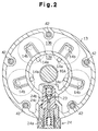
- a motor housing 41 is joined to the rear of the rear housing member 13. As shown in Figs. 1 and 2, bolts 42 fasten together the housing members 11, 12, 13 and the motor housing 41.
- the rear end of the drive shaft 16A passes through the rear housing 13 and is located in the motor housing 41.
- the part of the drive shaft 16A located in the motor housing 41 functions as an output shaft 16B of the electric motor 4.
- the rear end of the drive shaft 16A, or the end of the output shaft 16B, is supported by a cylindrical boss 41a through a radial bearing 17C.
- the cylindrical boss 41a is formed to the inner wall of the motor housing 41.
- a rotor 43 is fixed to the output shaft 16B.
- a stator coil 45 is attached the inner wall of the motor housing 41 to surround the rotor 43.
- a through hole 13c for permitting the passage of the drive shaft 16A is formed in the rear wall of the rear housing member 13.
- the through hole 13c connects the suction chamber 13a to an inner space 44 of the motor housing 41.
- An inlet is formed in the rear wall of the motor housing 41 and connects an external circuit 60 to the inner space 44.
- An outlet 13d is formed in a peripheral portion of the rear housing 13 and connects the external circuit 60 to the discharge chamber 13b.
- Refrigerant gas is supplied from the external circuit 60 to the suction chamber 13a through the inlet 41b, the inner space 44, and the through hole 13c. Compressed refrigerant gas is discharged from the discharge chamber 13b to the external circuit 60 through the outlet 13d.
- the external circuit 60 and the compressor constitute a refrigeration circuit for vehicle air conditioning.
- the external circuit 60 includes a condenser 61, an expansion valve 62, and an evaporator 63.
- a temperature sensor 56 detects temperature at the outlet of the evaporator 63 and outputs signals indicating the detection result to the controller 51.
- the temperature at the outlet of the evaporator 63 reflects a thermal load on the refrigeration circuit.
- the controller 51 which is a computer, includes a central processing unit (CPU) 52 for various computations, a read only memory (ROM) 53 for storing programs, and a random access memory (RAM) 54 for temporarily memorizing data.
- the detection signals from the temperature sensor 56 and an electric current sensor 57 are input to the CPU 52 through an input interface 55.
- the CPU 52 calculates the thermal load on the refrigeration circuit based on the temperature at the outlet of the evaporator 63 detected by the temperature sensor 56.
- the CPU 52 calculates torque of the motor 4 based on the value of electric current supply to the motor 4, which is detected by the electric current sensor 57.
- the CPU 52 controls the solenoid 37 of the electromagnetic clutch 2, the solenoid 24a of the control valve 24, and the drive circuit 7 by way of the output interface 58.
- the controller 51 engages the clutch 2 and instructs the drive circuit 7 to stop the supply of electric current from the battery to the motor 4. Accordingly, the engine 3 drives the compression mechanism 1.
- the controller 51 controls the control valve 24 in accordance with the temperature detected by the sensor 56 at the outlet of the evaporator 63, or the thermal load on the refrigeration circuit.
- the controller 51 judges that the cooling capacity of the refrigeration circuit is insufficient.
- the controller 51 closes the control valve 24 by feeding electric current to the solenoid 24a. Accordingly, the supply of refrigerant gas from the discharge chamber 13b to the crank chamber 15 through the pressurizing passage 23 is stopped, which reduces the pressure in the crank chamber 15. As a result, the inclination of the swash plate 19 increases, which increases the displacement of the compression mechanism 1.
- the controller 51 judges that the cooling capacity of the refrigeration circuit is excessive and opens the control valve 24 by stopping the supply of electric current. Accordingly, refrigerant gas is supplied from the discharge chamber 13b to the crank chamber 15 through the pressurizing passage 23, which increases the pressure in the crank chamber 15. As a result, the inclination of the swash plate 19 decreases, which decreases the displacement of the compression mechanism 1.
- the controller may perform duty-cycle control to control the electric current supplied to the control valve 24 in accordance with the thermal load on the refrigeration circuit.
- the excitation time of the control valve 24 to the de-excitation time is changed.
- the ratio of closing time of the pressurizing passage 23 to the opening time is changed, which adjusts the flow rate of refrigerant gas in the pressurizing passage.
- the inclination of the swash plate 19 is adjusted to an arbitrary inclination between the minimum inclination and the maximum inclination.
- the displacement of the compression mechanism 1 is adjusted to an arbitrary displacement between the maximum displacement and the minimum displacement in accordance with the thermal load of the refrigeration circuit.
- the controller 51 turns off the clutch 2 and separates the drive shaft 16A of the compression mechanism 1 from the engine 3. Simultaneously, the controller 51 controls the drive circuit 7 to supply electric current from the battery 5 to the motor 4. Therefore, the output shaft 16B of the motor 4 rotates and drives the compression mechanism.
- the displacement of the compressor mechanism, or the cooling capacity of the refrigeration circuit is adjusted by controlling the inclination of the swash plate 19.
- the cooling capacity of the refrigeration circuit is adjusted by controlling the inclination of the swash plate 19 and the rotation speed of the motor 4.
- the controller 51 adjusts the inclination of the swash plate 19 and the rotation speed of the motor 4 by controlling the control valve 24 and the drive circuit 7 so that the compression mechanism 1 and the motor 4 are most efficiently operated to achieve the required cooling capacity.
- the controller 51 considers not only the detection signal of the temperature sensor 56 (thermal load on the refrigeration circuit) but also the torque of the motor and other conditions. As a result, the compressor operates efficiently and avoids excessive load on the motor 4 while minimizing the power consumption of the motor 4.
- the controller 51 turns on the clutch 2 and instructs the drive circuit 7 to stop the supply of electric current to the motor 4. Accordingly, the operation of the compression mechanism 1 is restarted by the engine 3, and the battery is charged again by the electromotive force generated in the motor 4.
- the illustrated hybrid compressor has the following advantages.
- the present invention can be further varied as follows.
- the middle bearing 17B of the drive shaft 16A may be omitted, and only the ends of the drive shaft 16A may be supported by the two bearings 17A, 17C. This also simplifies the compressor.
- the output shaft 16B of the motor 4 forms part of the drive shaft 16A of the compression mechanism 1.
- the output shaft 16B may be an independent part and may be coupled to the drive shaft 16A by a coupler.
- refrigerant gas is drawn from the external circuit 60 to the suction chamber 13a through the inner space 44 of the motor 4.
- an inlet from the external circuit 60 in the suction chamber 13a may be formed to the rear housing member 13, bypassing the internal space 44 of the motor 4.
- the displacement of the compressor is varied by varying the stroke of the pistons 21 according to the inclination angle of the swash plate 19.
- the present invention may be embodied in other types of compressors, such as, fixed displacement piston type compressors, variable displacement vane type compressors or variable displacement scroll type compressors.
- a hybrid compressor that is selectively driven by an engine (3) and a motor (4).
- a compression mechanism (1) includes a drive shaft (16A).
- a clutch (2) is attached to the front of the compression mechanism (1), and the motor (4) is attached to the rear of the compression mechanism (1).
- the motor (4) has an output shaft (16B) connected to the drive shaft (16A).
- the clutch (2) selectively transmits power from the engine (3) to the drive shaft (16A).
Landscapes
- Engineering & Computer Science (AREA)
- Mechanical Engineering (AREA)
- General Engineering & Computer Science (AREA)
- Manufacturing & Machinery (AREA)
- Chemical & Material Sciences (AREA)
- Combustion & Propulsion (AREA)
- Compressors, Vaccum Pumps And Other Relevant Systems (AREA)
Applications Claiming Priority (2)
| Application Number | Priority Date | Filing Date | Title |
|---|---|---|---|
| JP10224951A JP2000054956A (ja) | 1998-08-07 | 1998-08-07 | ハイブリッドコンプレッサ |
| JP22495198 | 1998-08-07 |
Publications (2)
| Publication Number | Publication Date |
|---|---|
| EP0978653A2 true EP0978653A2 (fr) | 2000-02-09 |
| EP0978653A3 EP0978653A3 (fr) | 2000-10-11 |
Family
ID=16821757
Family Applications (1)
| Application Number | Title | Priority Date | Filing Date |
|---|---|---|---|
| EP99115581A Withdrawn EP0978653A3 (fr) | 1998-08-07 | 1999-08-06 | Compresseur hybride |
Country Status (3)
| Country | Link |
|---|---|
| US (1) | US6247899B1 (fr) |
| EP (1) | EP0978653A3 (fr) |
| JP (1) | JP2000054956A (fr) |
Cited By (11)
| Publication number | Priority date | Publication date | Assignee | Title |
|---|---|---|---|---|
| US6351957B2 (en) | 1999-06-10 | 2002-03-05 | Calsonic Kansei Corporation | Automotive air conditioning system |
| WO2002032706A1 (fr) * | 2000-10-17 | 2002-04-25 | Kabushiki Kaisha Toyota Jidoshokki | Systeme de generation de puissance et d"actionnement |
| EP1213166A1 (fr) * | 2000-12-07 | 2002-06-12 | Calsonic Kansei Corporation | Système de conditionnement d'air pour véhicule automobile |
| FR2827096A1 (fr) * | 2001-07-04 | 2003-01-10 | Toyota Jidoshokki Kk | Unite d'entrainement pour compresseur electrique a deplacement variable |
| EP1232885A3 (fr) * | 2001-02-15 | 2003-09-03 | Carrier Corporation | Générateur pour une unité de réfrigération à alimentation électrique |
| DE10101975C2 (de) * | 2000-01-18 | 2003-10-09 | Toyoda Automatic Loom Works | Motorgetriebener Kompressor, der durch Kühlgas gekühlt ist |
| EP1335133A3 (fr) * | 2002-02-08 | 2003-10-29 | Sanden Corporation | Compresseurs à deux étages |
| EP1331115A3 (fr) * | 2002-01-23 | 2004-04-21 | Sanden Corporation | Dispositif de climatisation d'un véhicule utilisant un compresseur hybride |
| EP1454777A1 (fr) * | 2003-03-04 | 2004-09-08 | Delphi Technologies, Inc. | Générateur-démarreur et compresseur de climatisation intégré et système et procédé de commande associés |
| EP2312156A3 (fr) * | 2009-09-04 | 2013-01-16 | Toyota Jidoshokki Kk | Compresseur pour une utilisation dans un véhicule |
| CN105781928A (zh) * | 2014-09-05 | 2016-07-20 | 现代自动车株式会社 | 混合压缩机 |
Families Citing this family (37)
| Publication number | Priority date | Publication date | Assignee | Title |
|---|---|---|---|---|
| JP2000130323A (ja) | 1998-10-29 | 2000-05-12 | Zexel Corp | ハイブリッドコンプレッサ |
| JP2001193639A (ja) * | 2000-01-11 | 2001-07-17 | Toyota Autom Loom Works Ltd | 電動斜板圧縮機 |
| JP2002054662A (ja) * | 2000-08-11 | 2002-02-20 | Toyota Industries Corp | 動力伝達機構 |
| JP2002276775A (ja) * | 2001-03-19 | 2002-09-25 | Toyota Industries Corp | 回転体装置 |
| JP4240837B2 (ja) * | 2001-03-30 | 2009-03-18 | 三洋電機株式会社 | 冷凍装置 |
| JP2002364535A (ja) * | 2001-06-08 | 2002-12-18 | Toyota Industries Corp | 回転装置 |
| JP2003074476A (ja) * | 2001-08-31 | 2003-03-12 | Nippon Soken Inc | 圧縮機制御装置 |
| JP4044341B2 (ja) * | 2001-09-14 | 2008-02-06 | サンデン株式会社 | ハイブリッド圧縮機 |
| JP3741022B2 (ja) * | 2001-10-15 | 2006-02-01 | 株式会社豊田自動織機 | 車両用空調装置 |
| JP3818137B2 (ja) * | 2001-11-27 | 2006-09-06 | 株式会社豊田自動織機 | 空調装置 |
| JP3698095B2 (ja) * | 2001-11-29 | 2005-09-21 | 株式会社豊田自動織機 | 車両用回転機械 |
| US6638027B2 (en) * | 2001-12-11 | 2003-10-28 | Visteon Global Technologies, Inc. | Hybrid compressor with bearing clutch assembly |
| US6715995B2 (en) * | 2002-01-31 | 2004-04-06 | Visteon Global Technologies, Inc. | Hybrid compressor control method |
| JP2003254273A (ja) * | 2002-03-06 | 2003-09-10 | Sanden Corp | 車両空調用2段圧縮機 |
| JP3917002B2 (ja) | 2002-05-15 | 2007-05-23 | サンデン株式会社 | 車両用空調装置 |
| JP2003335126A (ja) * | 2002-05-17 | 2003-11-25 | Mitsubishi Electric Corp | 車両用空気調和機 |
| JP2003341352A (ja) * | 2002-05-29 | 2003-12-03 | Toyota Industries Corp | ハイブリッドコンプレッサシステム |
| JP2004017920A (ja) * | 2002-06-20 | 2004-01-22 | Sanden Corp | 自動車用空調装置 |
| JP3955504B2 (ja) * | 2002-06-27 | 2007-08-08 | サンデン株式会社 | 車両空調装置用ハイブリッド圧縮機の起動方法 |
| JP4526755B2 (ja) * | 2002-06-27 | 2010-08-18 | サンデン株式会社 | 車両用空調装置 |
| JP2004066847A (ja) | 2002-08-01 | 2004-03-04 | Sanden Corp | 車両用空調装置 |
| JP4156955B2 (ja) * | 2002-09-19 | 2008-09-24 | サンデン株式会社 | 車両空調装置用ハイブリッド圧縮機の駆動方法 |
| WO2004064241A1 (fr) * | 2003-01-10 | 2004-07-29 | Matsushita Electric Industrial Co., Ltd. | Systeme de conditionnement d'air que l'on utilise dans un vehicule |
| JP3964812B2 (ja) * | 2003-03-11 | 2007-08-22 | サンデン株式会社 | 圧縮機用電磁クラッチ |
| JP3919686B2 (ja) * | 2003-03-14 | 2007-05-30 | サンデン株式会社 | ハイブリッド圧縮機 |
| JP4376651B2 (ja) * | 2003-03-17 | 2009-12-02 | サンデン株式会社 | 車両用空調装置 |
| JP4362394B2 (ja) * | 2003-03-28 | 2009-11-11 | Ntn株式会社 | コンプレッサ用軸受 |
| JP2004324591A (ja) * | 2003-04-25 | 2004-11-18 | Toyota Industries Corp | ハイブリッドコンプレッサ |
| JP4070740B2 (ja) * | 2004-03-31 | 2008-04-02 | 株式会社デンソー | 流体機械用の切替え弁構造 |
| DE102005031511A1 (de) * | 2005-07-06 | 2007-01-11 | Daimlerchrysler Ag | Steuerungsventil für einen Kältemittelverdichter und Kältemittelverdichter |
| US20080314059A1 (en) * | 2007-06-20 | 2008-12-25 | Thermo King Corporation | Double clutch drive system |
| US20110114405A1 (en) * | 2009-11-17 | 2011-05-19 | Perhats Frank J | Drive isolation system for traction engine driven accessories |
| US8602143B2 (en) * | 2011-03-17 | 2013-12-10 | GM Global Technology Operations LLC | Electric vehicle with range-extending engine and climate control compressor |
| US9145877B2 (en) * | 2011-11-22 | 2015-09-29 | Thermo King Corporation | Compressor unloading device |
| WO2014094607A1 (fr) * | 2012-12-17 | 2014-06-26 | Lan Wei | Compresseur à deux modes de propulsion |
| CN105041608A (zh) * | 2015-08-20 | 2015-11-11 | 欧星 | 一种汽车电及发动机两驱制冷机 |
| DE102019124516A1 (de) * | 2019-09-12 | 2021-03-18 | Hanon Systems | Positionieranordnung |
Citations (1)
| Publication number | Priority date | Publication date | Assignee | Title |
|---|---|---|---|---|
| JPH0687678A (ja) | 1992-09-02 | 1994-03-29 | Osaka Gas Co Ltd | コンクリートおよびコンクリート仕上げ剤 |
Family Cites Families (9)
| Publication number | Priority date | Publication date | Assignee | Title |
|---|---|---|---|---|
| DE2705869C2 (de) | 1977-02-11 | 1979-05-03 | Motorheizung Gmbh, 3000 Hannover | Wärmepumpenheizungssystem |
| JPS57159976A (en) | 1981-03-26 | 1982-10-02 | Mitsubishi Heavy Ind Ltd | Compressor |
| US4531379A (en) * | 1983-10-14 | 1985-07-30 | Diefenthaler Jr Robert E | Auxiliary power system for vehicle air conditioner and heater |
| JP3298126B2 (ja) | 1992-01-14 | 2002-07-02 | 株式会社日立製作所 | 冷媒圧縮機 |
| DE19513710B4 (de) | 1994-04-20 | 2006-05-04 | Volkswagen Ag | Verfahren zum Betrieb einer Klimaanlage und Anordnung derselben in einem Kraftfahrzeug |
| DE4432272C2 (de) | 1994-09-09 | 1997-05-15 | Daimler Benz Ag | Verfahren zum Betreiben einer Kälteerzeugungsanlage für das Klimatisieren von Fahrzeugen und eine Kälteerzeugungsanlage zur Durchführung desselben |
| US5617732A (en) * | 1995-06-19 | 1997-04-08 | Albader; Rashaid A. | Automotive air conditioning system |
| US5867996A (en) * | 1997-02-24 | 1999-02-09 | Denso Corporation | Compressor control device for vehicle air conditioner |
| DE19738250C2 (de) | 1997-09-02 | 2000-11-16 | Daimler Chrysler Ag | Kraftfahrzeugklimaanlage mit Kompressoreinheit |
-
1998
- 1998-08-07 JP JP10224951A patent/JP2000054956A/ja active Pending
-
1999
- 1999-08-03 US US09/365,922 patent/US6247899B1/en not_active Expired - Fee Related
- 1999-08-06 EP EP99115581A patent/EP0978653A3/fr not_active Withdrawn
Patent Citations (1)
| Publication number | Priority date | Publication date | Assignee | Title |
|---|---|---|---|---|
| JPH0687678A (ja) | 1992-09-02 | 1994-03-29 | Osaka Gas Co Ltd | コンクリートおよびコンクリート仕上げ剤 |
Cited By (13)
| Publication number | Priority date | Publication date | Assignee | Title |
|---|---|---|---|---|
| US6351957B2 (en) | 1999-06-10 | 2002-03-05 | Calsonic Kansei Corporation | Automotive air conditioning system |
| US6793464B2 (en) | 2000-01-18 | 2004-09-21 | Kabushiki Kaisha Toyoda Jidoshokki Seisakusho | Motor-driven compressor cooled by refrigerant gas |
| DE10101975C2 (de) * | 2000-01-18 | 2003-10-09 | Toyoda Automatic Loom Works | Motorgetriebener Kompressor, der durch Kühlgas gekühlt ist |
| WO2002032706A1 (fr) * | 2000-10-17 | 2002-04-25 | Kabushiki Kaisha Toyota Jidoshokki | Systeme de generation de puissance et d"actionnement |
| EP1213166A1 (fr) * | 2000-12-07 | 2002-06-12 | Calsonic Kansei Corporation | Système de conditionnement d'air pour véhicule automobile |
| EP1232885A3 (fr) * | 2001-02-15 | 2003-09-03 | Carrier Corporation | Générateur pour une unité de réfrigération à alimentation électrique |
| FR2827096A1 (fr) * | 2001-07-04 | 2003-01-10 | Toyota Jidoshokki Kk | Unite d'entrainement pour compresseur electrique a deplacement variable |
| EP1331115A3 (fr) * | 2002-01-23 | 2004-04-21 | Sanden Corporation | Dispositif de climatisation d'un véhicule utilisant un compresseur hybride |
| EP1335133A3 (fr) * | 2002-02-08 | 2003-10-29 | Sanden Corporation | Compresseurs à deux étages |
| EP1454777A1 (fr) * | 2003-03-04 | 2004-09-08 | Delphi Technologies, Inc. | Générateur-démarreur et compresseur de climatisation intégré et système et procédé de commande associés |
| US6823690B2 (en) | 2003-03-04 | 2004-11-30 | Delphi Technologies, Inc. | Integrated electrical generator/starter and air conditioning compressor device and system and method for controlling same |
| EP2312156A3 (fr) * | 2009-09-04 | 2013-01-16 | Toyota Jidoshokki Kk | Compresseur pour une utilisation dans un véhicule |
| CN105781928A (zh) * | 2014-09-05 | 2016-07-20 | 现代自动车株式会社 | 混合压缩机 |
Also Published As
| Publication number | Publication date |
|---|---|
| US6247899B1 (en) | 2001-06-19 |
| JP2000054956A (ja) | 2000-02-22 |
| EP0978653A3 (fr) | 2000-10-11 |
Similar Documents
| Publication | Publication Date | Title |
|---|---|---|
| US6247899B1 (en) | Dual driven hybrid compressor | |
| US6230507B1 (en) | Hybrid compressor and control method | |
| US6640562B2 (en) | Air-conditioning system for vehicle and its control method | |
| US6662580B2 (en) | Air-conditioning system for vehicle and its control method | |
| US6318971B1 (en) | Variable displacement compressor | |
| US20020067999A1 (en) | Rotational apparatus unit | |
| US6250093B1 (en) | Air conditioning system and compressor | |
| US6848262B2 (en) | Compressor device and control method for the same | |
| US6617727B2 (en) | Vehicular rotational apparatus | |
| US6203284B1 (en) | Valve arrangement at the discharge chamber of a variable displacement compressor | |
| US6619929B2 (en) | Rotational apparatus | |
| US6719538B2 (en) | Rotating apparatus | |
| US20030098216A1 (en) | One-way clutch assembly and one-way power transmission clutch unit with the same | |
| US6241483B1 (en) | Variable displacement compressor | |
| US6821094B2 (en) | Hybrid power transmission system having first and second clutch mechanisms | |
| US20040052647A1 (en) | Compressor | |
| JP2002285973A (ja) | 冷凍サイクルの圧縮容量制御装置 | |
| US20040055843A1 (en) | Power generation and actuating system | |
| US20030103848A1 (en) | Rotary machine for vehicle | |
| JP2000265948A (ja) | 可変容量型圧縮機 | |
| US20010043866A1 (en) | Electric compressor | |
| JP2004211589A (ja) | 圧縮機 | |
| JP3908009B2 (ja) | 車両用冷房装置 | |
| JP2002205536A (ja) | 車両用空調システム | |
| KR20200124521A (ko) | 사판식 압축기 |
Legal Events
| Date | Code | Title | Description |
|---|---|---|---|
| PUAI | Public reference made under article 153(3) epc to a published international application that has entered the european phase |
Free format text: ORIGINAL CODE: 0009012 |
|
| 17P | Request for examination filed |
Effective date: 19990806 |
|
| AK | Designated contracting states |
Kind code of ref document: A2 Designated state(s): DE FR IT |
|
| AX | Request for extension of the european patent |
Free format text: AL;LT;LV;MK;RO;SI |
|
| PUAL | Search report despatched |
Free format text: ORIGINAL CODE: 0009013 |
|
| AK | Designated contracting states |
Kind code of ref document: A3 Designated state(s): AT BE CH CY DE DK ES FI FR GB GR IE IT LI LU MC NL PT SE |
|
| AX | Request for extension of the european patent |
Free format text: AL;LT;LV;MK;RO;SI |
|
| RIC1 | Information provided on ipc code assigned before grant |
Free format text: 7F 04B 35/00 A, 7F 04B 27/08 B |
|
| AKX | Designation fees paid |
Free format text: DE FR IT |
|
| RAP1 | Party data changed (applicant data changed or rights of an application transferred) |
Owner name: KABUSHIKI KAISHA TOYOTA JIDOSHOKKI |
|
| 17Q | First examination report despatched |
Effective date: 20050301 |
|
| STAA | Information on the status of an ep patent application or granted ep patent |
Free format text: STATUS: THE APPLICATION IS DEEMED TO BE WITHDRAWN |
|
| 18D | Application deemed to be withdrawn |
Effective date: 20050712 |