EP0978669A2 - Schalthebel mit Handschalt- und Automatikmodus für Automatikgetriebe - Google Patents
Schalthebel mit Handschalt- und Automatikmodus für Automatikgetriebe Download PDFInfo
- Publication number
- EP0978669A2 EP0978669A2 EP99108759A EP99108759A EP0978669A2 EP 0978669 A2 EP0978669 A2 EP 0978669A2 EP 99108759 A EP99108759 A EP 99108759A EP 99108759 A EP99108759 A EP 99108759A EP 0978669 A2 EP0978669 A2 EP 0978669A2
- Authority
- EP
- European Patent Office
- Prior art keywords
- select lever
- shift
- lever
- select
- cable bracket
- Prior art date
- Legal status (The legal status is an assumption and is not a legal conclusion. Google has not performed a legal analysis and makes no representation as to the accuracy of the status listed.)
- Granted
Links
Images


Classifications
-
- B—PERFORMING OPERATIONS; TRANSPORTING
- B60—VEHICLES IN GENERAL
- B60K—ARRANGEMENT OR MOUNTING OF PROPULSION UNITS OR OF TRANSMISSIONS IN VEHICLES; ARRANGEMENT OR MOUNTING OF PLURAL DIVERSE PRIME-MOVERS IN VEHICLES; AUXILIARY DRIVES FOR VEHICLES; INSTRUMENTATION OR DASHBOARDS FOR VEHICLES; ARRANGEMENTS IN CONNECTION WITH COOLING, AIR INTAKE, GAS EXHAUST OR FUEL SUPPLY OF PROPULSION UNITS IN VEHICLES
- B60K20/00—Arrangement or mounting of change-speed gearing control devices in vehicles
- B60K20/02—Arrangement or mounting of change-speed gearing control devices in vehicles of initiating means
-
- F—MECHANICAL ENGINEERING; LIGHTING; HEATING; WEAPONS; BLASTING
- F16—ENGINEERING ELEMENTS AND UNITS; GENERAL MEASURES FOR PRODUCING AND MAINTAINING EFFECTIVE FUNCTIONING OF MACHINES OR INSTALLATIONS; THERMAL INSULATION IN GENERAL
- F16H—GEARING
- F16H59/00—Control inputs to control units of change-speed- or reversing-gearings for conveying rotary motion
- F16H59/02—Selector apparatus
- F16H59/0204—Selector apparatus for automatic transmissions with means for range selection and manual shifting, e.g. range selector with tiptronic
-
- F—MECHANICAL ENGINEERING; LIGHTING; HEATING; WEAPONS; BLASTING
- F16—ENGINEERING ELEMENTS AND UNITS; GENERAL MEASURES FOR PRODUCING AND MAINTAINING EFFECTIVE FUNCTIONING OF MACHINES OR INSTALLATIONS; THERMAL INSULATION IN GENERAL
- F16H—GEARING
- F16H59/00—Control inputs to control units of change-speed- or reversing-gearings for conveying rotary motion
- F16H59/02—Selector apparatus
- F16H2059/0239—Up- and down-shift or range or mode selection by repeated movement
-
- F—MECHANICAL ENGINEERING; LIGHTING; HEATING; WEAPONS; BLASTING
- F16—ENGINEERING ELEMENTS AND UNITS; GENERAL MEASURES FOR PRODUCING AND MAINTAINING EFFECTIVE FUNCTIONING OF MACHINES OR INSTALLATIONS; THERMAL INSULATION IN GENERAL
- F16H—GEARING
- F16H59/00—Control inputs to control units of change-speed- or reversing-gearings for conveying rotary motion
- F16H59/02—Selector apparatus
- F16H59/08—Range selector apparatus
- F16H59/10—Range selector apparatus comprising levers
-
- Y—GENERAL TAGGING OF NEW TECHNOLOGICAL DEVELOPMENTS; GENERAL TAGGING OF CROSS-SECTIONAL TECHNOLOGIES SPANNING OVER SEVERAL SECTIONS OF THE IPC; TECHNICAL SUBJECTS COVERED BY FORMER USPC CROSS-REFERENCE ART COLLECTIONS [XRACs] AND DIGESTS
- Y10—TECHNICAL SUBJECTS COVERED BY FORMER USPC
- Y10T—TECHNICAL SUBJECTS COVERED BY FORMER US CLASSIFICATION
- Y10T74/00—Machine element or mechanism
- Y10T74/20—Control lever and linkage systems
- Y10T74/20012—Multiple controlled elements
- Y10T74/20018—Transmission control
- Y10T74/20067—Control convertible between automatic and manual operation
-
- Y—GENERAL TAGGING OF NEW TECHNOLOGICAL DEVELOPMENTS; GENERAL TAGGING OF CROSS-SECTIONAL TECHNOLOGIES SPANNING OVER SEVERAL SECTIONS OF THE IPC; TECHNICAL SUBJECTS COVERED BY FORMER USPC CROSS-REFERENCE ART COLLECTIONS [XRACs] AND DIGESTS
- Y10—TECHNICAL SUBJECTS COVERED BY FORMER USPC
- Y10T—TECHNICAL SUBJECTS COVERED BY FORMER US CLASSIFICATION
- Y10T74/00—Machine element or mechanism
- Y10T74/20—Control lever and linkage systems
- Y10T74/20012—Multiple controlled elements
- Y10T74/20018—Transmission control
- Y10T74/20085—Restriction of shift, gear selection, or gear engagement
- Y10T74/20104—Shift element interlock
- Y10T74/2011—Shift element interlock with detent, recess, notch, or groove
-
- Y—GENERAL TAGGING OF NEW TECHNOLOGICAL DEVELOPMENTS; GENERAL TAGGING OF CROSS-SECTIONAL TECHNOLOGIES SPANNING OVER SEVERAL SECTIONS OF THE IPC; TECHNICAL SUBJECTS COVERED BY FORMER USPC CROSS-REFERENCE ART COLLECTIONS [XRACs] AND DIGESTS
- Y10—TECHNICAL SUBJECTS COVERED BY FORMER USPC
- Y10T—TECHNICAL SUBJECTS COVERED BY FORMER US CLASSIFICATION
- Y10T74/00—Machine element or mechanism
- Y10T74/20—Control lever and linkage systems
- Y10T74/20012—Multiple controlled elements
- Y10T74/20018—Transmission control
- Y10T74/20085—Restriction of shift, gear selection, or gear engagement
- Y10T74/20104—Shift element interlock
- Y10T74/20116—Resiliently biased interlock
-
- Y—GENERAL TAGGING OF NEW TECHNOLOGICAL DEVELOPMENTS; GENERAL TAGGING OF CROSS-SECTIONAL TECHNOLOGIES SPANNING OVER SEVERAL SECTIONS OF THE IPC; TECHNICAL SUBJECTS COVERED BY FORMER USPC CROSS-REFERENCE ART COLLECTIONS [XRACs] AND DIGESTS
- Y10—TECHNICAL SUBJECTS COVERED BY FORMER USPC
- Y10T—TECHNICAL SUBJECTS COVERED BY FORMER US CLASSIFICATION
- Y10T74/00—Machine element or mechanism
- Y10T74/20—Control lever and linkage systems
- Y10T74/20012—Multiple controlled elements
- Y10T74/20018—Transmission control
- Y10T74/20085—Restriction of shift, gear selection, or gear engagement
- Y10T74/20128—Resiliently biased restrictor
Definitions
- the present invention relates to a shift/select lever unit for dual-mode automatic transmissions in which both automatic and manual shifting capabilities are provided.
- the transmission has the conventional automatic modes, but enables manual control in the drive D range so that the driver can have more control over the vehicle. Such an arrangement is more often found in sports vehicles.
- a select lever unit used in the dual-mode automatic transmission generally includes a select lever operated by the user to change shift modes and ranges; a cable bracket connected to a shift cable and which is indexed with the select lever when the select lever is in an automatic mode to operate a manual valve of the transmission; and a connecting lever member formed on the select lever to enable the select lever and the cable bracket to move together according to changes in the automatic mode, the cable bracket being provided with a lever connecting hole corresponding to the connecting lever member.
- An indentation is provided on an upper portion of the lever connecting hole for insertion of the connecting lever member to fix the connecting lever members relative motion with respect to the cable bracket along certain directions when the select lever is in the automatic mode, thereby forming an automatic mode range.
- a bottom portion of the lever connecting hole is realized through a manual mode range having a predetermined width to enable freer movement of the connecting lever member during plus and minus shifting in the case where the select lever is in the automatic shift mode.
- the operation of the select lever unit is such that the connecting lever member selectively moves in ranges in the lever connecting hole according to mode changes of the select lever, thereby either transmitting or discontinuing operational force of the select lever on the shift cable.
- the connecting lever member When the select lever is in the automatic mode, the connecting lever member is inserted in the automatic mode range of the lever connecting hole such that the select lever and the cable bracket integrally move together, and if the select lever is converted to a manual mode, the connecting lever member is removed from the automatic mode range of the lever connecting hole such that the select lever and the cable bracket no longer integrally move together.
- the cable bracket In the manual mode, the cable bracket must be fixed in the drive range. This is realized by the action of a detent spring formed on one side of the cable bracket and a detent plate formed on a main frame.
- the degree to which the cable bracket is secured in the drive range is dependent upon the operation of the elastic force of the detent spring on a groove of the detent plate. As a result, shaking or vibrations of the vehicle body can compromise the anchoring of the cable bracket in the drive range, possibly resulting in safety problems.
- the present invention has been made in an effort to solve the above problem.
- the shift/select lever unit for a dual-mode automatic transmission.
- the shift/select lever unit includes a main frame mounted to a vehicle body; a select lever assembly movable between the automatic and manual modes to select one of the automatic and manual modes, the select lever assembly being shiftable in the automatic and manual modes to change drive modes and ranges; a shift cable bracket connected to a shift cable, the shift cable bracket being engaged with the select lever assembly when the select lever assembly is in the automatic mode and released from the select lever assembly when the select lever assembly is in the manual mode; and means for preventing the shift cable bracket from moving when the select lever assembly is in the manual mode.
- the shift cable bracket is provided with a select lever releasing/engaging hole
- the select lever assembly comprises a select lever pivotally mounted on the main frame and a connecting lever fixedly mounted on the select lever and extending toward the select lever releasing/engaging hole of the shift cable bracket, the connecting lever being located in the select lever engaging section when the select lever is in the automatic mode and located in the select lever releasing section when the select lever is in the manual mode.
- a detent plate is mounted on the main frame and having a plurality of grooves and a detent spring having a first end mounted on the bracket and a second end engaged with the grooves of the detent plate such that a suitable detent feeling is provided to the select lever assembly when the select lever assembly changes ranges in the automatic mode.
- the means for preventing the shift cable bracket from moving includes a push lever mounted on the select lever assembly and extending toward the shift cable bracket; and a flat spring mounted on the main frame and disposed between the push lever and the shift cable bracket, the flat spring being designed to be forced toward the shift cable bracket by the push lever when the select lever assembly is displaced to the manual mode, thereby preventing the shift cable bracket from moving in the manual mode.
- the means for preventing the shift cable bracket from moving further comprises a stopper integrally formed on the push lever, the stopper being inserted into a stopper hole formed on the shift cable bracket when the select lever assembly is displaced to the manual mode.
- the detent spring has a predetermined degree of elasticity to provide the detent feeling, is screw-coupled to the shift cable bracket, and is rounded on the second end engaged with the grooves of the detent plate.
- a portion of the flat spring contacting the push lever is formed such that a larger area is provided for contact with the push lever when the select lever assembly is displaced from the automatic mode to the manual mode.
- the select lever engaging/releasing hole has an automatic mode section and a manual mode section, the manual mode section being larger than the automatic mode section.
- the connecting lever is provided at its extreme end within the select lever engaging/releasing hole with a sound absorbing member so as to prevent the generation of noise when the connecting lever associated with the select lever moves in the select lever engaging/releasing hole.
- Fig. 1 shows a top view of a select lever unit according to a first preferred embodiment of the present invention. Passing through a shift plate 1 of the select lever unit is a select lever 2.
- a passageway 100 is provided in the shift plate 1 and shift mode markers are illustrated on the shift plate 1 adjacent to the passageway 100.
- the shift mode markers include those corresponding to automatic shift control (i.e., P, R, N and D) and those corresponding to manual shift control (i.e., + and -).
- the user manipulates the select lever 2 in the passageway 100 to be positioned at one of the automatic shift modes, and, in the drive D range, controls the select lever 2 to the right and upward or downward respectively to the upshift (+) or downshift (-) marker to realize manual shifting. This will be described in more detail hereinafter.
- Fig. 2 is a sectional view taken along line II-II of Fig. 1
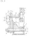
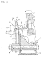
- Fig. 3 is a sectional view taken along line III-III of Fig. 1.
- a cable bracket 3 is provided on one side of the select lever unit under the shift plate 1 and the select lever 2 is vertically mounted inwardly from the cable bracket 3.
- a bottom end of the select lever 2 is rotatably mounted to a hinge 7 of a reciprocating frame 4, and both a connecting lever 5 and a push lever 6 are mounted to a side surface of the select lever 2.
- the cable bracket 3 is rotatably connected to a hinge member 8, and includes a connecting lever hole 9 into which a distal end of the connecting lever 5 is inserted and a push lever hole 10 into which a stopper portion 17 of a flat spring 18 is inserted.
- the connecting lever 5 is inserted in the connecting lever hole 9 and the push lever 6 acts to insert the stopper portion 17 of the flat spring 18 in the push lever hole 10 to securely fix the select lever 2 to the cable bracket 3.
- a cable connector 11 is integrally formed in a top portion of the cable bracket 3, and one end of a shift cable (not shown), which is connected to a manual valve (not shown) of the automatic transmission, is joined to the cable connector 11.
- a detent spring 13 Connected to the cable bracket 3 in proximity to the cable connector 11 is a detent spring 13.
- the detent spring 13 is engaged with one of a plurality of grooves 20 formed on a detent plate 12, the detent plate 12 being fixed to a main frame 14. Therefore, the combination of the detent spring 13 and the cable bracket 3 conveys a checking, detent feeling to the user when he or she manipulates the shift lever 2 to one of the automatic shift ranges.
- the connecting lever hole 9 includes an auto mode section 15 and a manual mode section 16, the auto mode section 15 being smaller than the manual mode section 16.
- the connecting lever 5, cooperatively mounted to the select lever 2 is inserted in the auto mode section 15 when the selection lever 2 is positioned at one of the automatic shift mode markers such that the select lever 2 is fixed in its relative motion with respect to the cable bracket 3 in the radial direction about the hinge member 8.
- the connecting lever 5 is inserted in the manual mode section 16 such that the select lever 2 can be moved relative to the cable bracket 3 within the constraints of the wider manual mode section 16, thereby allowing the select lever 2 to be manually shift to the upshift and downshift markers (+) and (-).
- a sound absorbing member 21 is provided on an end of the connecting lever 5.
- the sound absorbing member 21 acts to reduce the sound generated by the connecting lever 5 making contact with the auto mode section 15 of the connecting lever hole 9. It is preferable that the sound absorbing member 21 made of rubber or other such resinous material to enable the effective absorption of contact noise between the connecting lever 5 and the connecting lever hole 9.
- a bottom end of the flat spring 18 is fixed to the main frame 14 and a top end of the flat spring 18 is bent to form a stopper portion 17.
- the stopper portion 17 of the flat spring 18 is inserted in the push lever hole 10 by the push operation of the push lever 6 associated with the select lever 2.
- a dish-shaped plate 22 is integrally formed at a portion of the flat spring 18 contacting the push lever 6. With the formation of the dish-shaped plate 22, a larger area is provided for contact with the push lever 6 when the push lever 6 undergoes its push operation during shifting of the select lever 2 from the automatic mode to the manual mode.
- the connecting lever 5, integrally formed to the select lever 2 is disengaged from the auto mode section 15 of the connecting lever hole 9 and engaged with the manual mode section 16 of the connecting lever hole 9.
- the push lever 6 of the select lever 2 moves so that it pushes the flat spring 18 such that the stopper 17 of the fiat spring 18 is inserted in the push lever hole 10 of the cable bracket 3.
- the connecting lever 5, integrally formed to the select lever 2 is disengaged from the manual mode section 16 of the connecting lever hole 9 and engaged with the auto mode section 15 of the connecting lever hole 9 such that the select lever 2 is unable to move with respect to the cable bracket 3 in a radial direction about the hinge member 8.
- the push lever 6 of the select lever 2 moves away from the flat spring 18 such that the stopper 17 of the push lever 6 is disengaged from the push lever hole 10 of the cable bracket 3 by the elastic force of the flat spring 18.
- the select lever 2 is able to operate the cable bracket 3 to each range in the automatic mode, with the operational force of the select lever 2 being transmitted by the connecting lever 5 and the connecting lever hole 9 to the auto mode section 15 of the cable bracket 3.
- the sound absorbing member 21 is not provided on the end of the connecting lever 5.
- the connecting lever 5 is made of a material that produces minimal noise when engaging the connecting lever hole 9.
Landscapes
- Engineering & Computer Science (AREA)
- General Engineering & Computer Science (AREA)
- Mechanical Engineering (AREA)
- Chemical & Material Sciences (AREA)
- Combustion & Propulsion (AREA)
- Transportation (AREA)
- Arrangement Or Mounting Of Control Devices For Change-Speed Gearing (AREA)
- Control Of Transmission Device (AREA)
- Gear-Shifting Mechanisms (AREA)
Applications Claiming Priority (2)
| Application Number | Priority Date | Filing Date | Title |
|---|---|---|---|
| KR9832177 | 1998-08-07 | ||
| KR1019980032177A KR100285496B1 (ko) | 1998-08-07 | 1998-08-07 | 자동변속기 셀렉터 레버 쉬프트 록 장치 |
Publications (3)
| Publication Number | Publication Date |
|---|---|
| EP0978669A2 true EP0978669A2 (de) | 2000-02-09 |
| EP0978669A3 EP0978669A3 (de) | 2000-12-06 |
| EP0978669B1 EP0978669B1 (de) | 2004-07-28 |
Family
ID=19546689
Family Applications (1)
| Application Number | Title | Priority Date | Filing Date |
|---|---|---|---|
| EP99108759A Expired - Lifetime EP0978669B1 (de) | 1998-08-07 | 1999-05-03 | Schalthebel mit Handschalt- und Automatikmodus für Automatikgetriebe |
Country Status (4)
| Country | Link |
|---|---|
| US (1) | US6196080B1 (de) |
| EP (1) | EP0978669B1 (de) |
| KR (1) | KR100285496B1 (de) |
| DE (1) | DE69918905T2 (de) |
Cited By (3)
| Publication number | Priority date | Publication date | Assignee | Title |
|---|---|---|---|---|
| DE10109960A1 (de) * | 2001-03-01 | 2002-09-05 | Bayerische Motoren Werke Ag | Wähleinrichtung für ein Automatikgetriebe |
| EP1262689A1 (de) * | 2001-05-30 | 2002-12-04 | Sila Holding Industriale S.p.A. | Vorrichtung zur Steuerung eines automatischen und sequentiellen Getriebes |
| EP2728224A1 (de) * | 2012-10-30 | 2014-05-07 | Kongsberg Automotive AB | Schaltanordnung mit drehbaren Zwillingskolben |
Families Citing this family (19)
| Publication number | Priority date | Publication date | Assignee | Title |
|---|---|---|---|---|
| KR100320520B1 (ko) * | 1999-12-28 | 2002-01-16 | 이계안 | 자동변속기 셀렉터 레버 쉬프트 록 장치 |
| KR100488693B1 (ko) * | 2002-06-27 | 2005-05-11 | 현대자동차주식회사 | 매뉴얼 모드 스위치가 구비된 자동변속기 레버 장치 |
| JP4205372B2 (ja) * | 2002-06-28 | 2009-01-07 | 富士重工業株式会社 | 自動変速機のセレクトシステム |
| USPP15990P3 (en) * | 2003-04-23 | 2005-09-20 | J. C. Bakker & Sons Limited | Lilac plant named ‘Golden Eclipse’ |
| US7393304B2 (en) | 2003-05-15 | 2008-07-01 | Grand Haven Stamped Products | Shifter with gear position indicator |
| US7221248B2 (en) * | 2003-05-15 | 2007-05-22 | Grand Haven Stamped Products | Solenoid with noise reduction |
| KR100488740B1 (ko) * | 2003-08-27 | 2005-05-11 | 현대자동차주식회사 | 차량용 시프트 바이 와이어 시스템의 시프팅 장치 |
| US7568404B2 (en) | 2004-07-26 | 2009-08-04 | Ghsp, A Division Of Jsj Corporation | Shifter having neutral lock |
| US7328782B2 (en) * | 2004-07-26 | 2008-02-12 | Grand Haven Stamped Products Company, A Division Of Jsj Corporation | Vehicle shifter with powered pawl having neutral lock |
| KR100756636B1 (ko) | 2006-06-28 | 2007-09-07 | 현대자동차주식회사 | 수동변속기용 변속레버 어셈블리 |
| KR101233516B1 (ko) * | 2006-09-26 | 2013-02-14 | 기아자동차주식회사 | 자동변속기의 쉬프트록 장치 |
| DE102010063153B4 (de) * | 2010-12-15 | 2012-09-20 | Jopp Gmbh | Schaltvorrichtung für ein Automatikgetriebe |
| DE102011053177A1 (de) * | 2011-08-31 | 2013-02-28 | ECS Engineered Control System AG | Schaltvorrichtung |
| US8656802B2 (en) * | 2011-09-30 | 2014-02-25 | Kongsberg Automotive Ab | Shifter assembly for providing mechanical and electronic actuation to a transmission of a vehicle and a method of operating the shifter assembly |
| US9377100B2 (en) | 2012-07-06 | 2016-06-28 | Kongsberg Automotive Ab | Shifter assembly |
| JP6407745B2 (ja) * | 2015-02-05 | 2018-10-17 | 株式会社東海理化電機製作所 | シフト装置 |
| CN107489759B (zh) * | 2016-08-24 | 2019-11-22 | 宝沃汽车(中国)有限公司 | 换挡杆总成、手自一体式换挡机构和车辆 |
| CN107489761B (zh) * | 2016-12-23 | 2020-03-06 | 北汽福田汽车股份有限公司 | 手自一体式换挡机构和车辆 |
| JP6698043B2 (ja) * | 2017-03-14 | 2020-05-27 | 株式会社東海理化電機製作所 | シフト装置 |
Family Cites Families (6)
| Publication number | Priority date | Publication date | Assignee | Title |
|---|---|---|---|---|
| DE3927250A1 (de) * | 1989-08-18 | 1991-02-21 | Porsche Ag | Schaltvorrichtung |
| EP0575658B1 (de) * | 1992-06-30 | 1998-10-28 | Aisin Aw Co., Ltd. | Schaltanlage mit manuellem Übersetzungswahlmechanismus für ein automatisches Kraftfahrzeuggetriebe |
| DE4426207C5 (de) * | 1994-07-23 | 2008-08-28 | Bayerische Motoren Werke Aktiengesellschaft | Wähleinrichtung für ein Automatikgetriebe eines Kraftfahrzeugs |
| US5799538A (en) * | 1995-04-11 | 1998-09-01 | Grand Haven Stamped Products Co. Div Of Jsj Corporation | Shifter with bottom mounted lever |
| US5899115A (en) * | 1995-10-24 | 1999-05-04 | Fuji Kiko Co., Ltd. | Shift select lever device for automatic transmission |
| IT1286287B1 (it) * | 1996-03-29 | 1998-07-08 | Roltra Morse Spa | Guida per una leva di selezione |
-
1998
- 1998-08-07 KR KR1019980032177A patent/KR100285496B1/ko not_active Expired - Fee Related
-
1999
- 1999-04-28 US US09/300,890 patent/US6196080B1/en not_active Expired - Fee Related
- 1999-05-03 DE DE69918905T patent/DE69918905T2/de not_active Expired - Fee Related
- 1999-05-03 EP EP99108759A patent/EP0978669B1/de not_active Expired - Lifetime
Non-Patent Citations (1)
| Title |
|---|
| None |
Cited By (3)
| Publication number | Priority date | Publication date | Assignee | Title |
|---|---|---|---|---|
| DE10109960A1 (de) * | 2001-03-01 | 2002-09-05 | Bayerische Motoren Werke Ag | Wähleinrichtung für ein Automatikgetriebe |
| EP1262689A1 (de) * | 2001-05-30 | 2002-12-04 | Sila Holding Industriale S.p.A. | Vorrichtung zur Steuerung eines automatischen und sequentiellen Getriebes |
| EP2728224A1 (de) * | 2012-10-30 | 2014-05-07 | Kongsberg Automotive AB | Schaltanordnung mit drehbaren Zwillingskolben |
Also Published As
| Publication number | Publication date |
|---|---|
| US6196080B1 (en) | 2001-03-06 |
| KR20000013359A (ko) | 2000-03-06 |
| DE69918905T2 (de) | 2005-08-11 |
| EP0978669A3 (de) | 2000-12-06 |
| DE69918905D1 (de) | 2004-09-02 |
| EP0978669B1 (de) | 2004-07-28 |
| KR100285496B1 (ko) | 2001-04-02 |
Similar Documents
| Publication | Publication Date | Title |
|---|---|---|
| US6196080B1 (en) | Shift lever unit for dual-mode automatic transmission | |
| EP0770799B1 (de) | Schalthebeleinrichtung für ein Automatikgetriebe | |
| US5509322A (en) | Shift control mechanism to manually shift an automatic transmission | |
| US4543842A (en) | Select return mechanism in a manual transmission for automotive vehicles | |
| US4365522A (en) | Shift lever mechanism of an automatic transmission | |
| US7137313B2 (en) | Shifting device for transmitting shift commands to an automatic transmission | |
| AU2003268823B2 (en) | A Shift Control Apparatus for a Transmission | |
| EP1452782A2 (de) | Schalthebelvorrichtung für Automatgetriebe | |
| EP0748958B1 (de) | Schaltsperrmechanismus für Schalthebel | |
| EP0459485B1 (de) | Schalteinrichtung eines automatischen Getriebes | |
| US6142034A (en) | Manual transmission shifter with reverse lockout device | |
| US5884529A (en) | Shifting device for an automatic transmission of a motor vehicle | |
| KR100721890B1 (ko) | 시프트 레버 장치 | |
| EP2009327A2 (de) | Gangschaltungsvorrichtung für ein Fahrzeug | |
| US6318209B1 (en) | Shift lever position adjustment device for an automotive vehicle | |
| EP0867642B1 (de) | Schalthebel | |
| JPH0529406Y2 (de) | ||
| KR20000015827U (ko) | 자동차의 변속레버 장착구조 | |
| US20050217404A1 (en) | Selector apparatus of an automatic transmission of vehicle | |
| KR100302305B1 (ko) | 자동변속레버의시프트록장치 | |
| JP3725664B2 (ja) | 自動変速機の変速操作入力装置 | |
| EP0823571A2 (de) | Lenkradschalthebel für automatisches Getriebe | |
| US20050217403A1 (en) | Selector apparatus of an automatic transmission of vehicle | |
| US11486491B2 (en) | Shift device for vehicle that includes a shift lever and a control lever that are separately supported by a baseplate | |
| JP4633385B2 (ja) | 変速機のチェンジ機構 |
Legal Events
| Date | Code | Title | Description |
|---|---|---|---|
| PUAI | Public reference made under article 153(3) epc to a published international application that has entered the european phase |
Free format text: ORIGINAL CODE: 0009012 |
|
| AK | Designated contracting states |
Kind code of ref document: A2 Designated state(s): DE FR GB |
|
| AX | Request for extension of the european patent |
Free format text: AL;LT;LV;MK;RO;SI |
|
| PUAL | Search report despatched |
Free format text: ORIGINAL CODE: 0009013 |
|
| AK | Designated contracting states |
Kind code of ref document: A3 Designated state(s): AT BE CH CY DE DK ES FI FR GB GR IE IT LI LU MC NL PT SE |
|
| AX | Request for extension of the european patent |
Free format text: AL;LT;LV;MK;RO;SI |
|
| 17P | Request for examination filed |
Effective date: 20010606 |
|
| AKX | Designation fees paid |
Free format text: DE FR GB |
|
| 17Q | First examination report despatched |
Effective date: 20020919 |
|
| GRAP | Despatch of communication of intention to grant a patent |
Free format text: ORIGINAL CODE: EPIDOSNIGR1 |
|
| GRAS | Grant fee paid |
Free format text: ORIGINAL CODE: EPIDOSNIGR3 |
|
| GRAA | (expected) grant |
Free format text: ORIGINAL CODE: 0009210 |
|
| AK | Designated contracting states |
Kind code of ref document: B1 Designated state(s): DE FR GB |
|
| REG | Reference to a national code |
Ref country code: GB Ref legal event code: FG4D |
|
| REF | Corresponds to: |
Ref document number: 69918905 Country of ref document: DE Date of ref document: 20040902 Kind code of ref document: P |
|
| ET | Fr: translation filed | ||
| PG25 | Lapsed in a contracting state [announced via postgrant information from national office to epo] |
Ref country code: GB Free format text: LAPSE BECAUSE OF NON-PAYMENT OF DUE FEES Effective date: 20050503 |
|
| PLBE | No opposition filed within time limit |
Free format text: ORIGINAL CODE: 0009261 |
|
| 26N | No opposition filed |
Effective date: 20050429 |
|
| PG25 | Lapsed in a contracting state [announced via postgrant information from national office to epo] |
Ref country code: DE Free format text: LAPSE BECAUSE OF NON-PAYMENT OF DUE FEES Effective date: 20051201 |
|
| GBPC | Gb: european patent ceased through non-payment of renewal fee |
Effective date: 20050503 |
|
| PG25 | Lapsed in a contracting state [announced via postgrant information from national office to epo] |
Ref country code: FR Free format text: LAPSE BECAUSE OF NON-PAYMENT OF DUE FEES Effective date: 20060131 |
|
| REG | Reference to a national code |
Ref country code: FR Ref legal event code: ST Effective date: 20060131 |