EP0978822A2 - Multidimensionaler Wandleranordnung - Google Patents
Multidimensionaler Wandleranordnung Download PDFInfo
- Publication number
- EP0978822A2 EP0978822A2 EP99306160A EP99306160A EP0978822A2 EP 0978822 A2 EP0978822 A2 EP 0978822A2 EP 99306160 A EP99306160 A EP 99306160A EP 99306160 A EP99306160 A EP 99306160A EP 0978822 A2 EP0978822 A2 EP 0978822A2
- Authority
- EP
- European Patent Office
- Prior art keywords
- dimensional
- transducer
- elements
- array
- bin
- Prior art date
- Legal status (The legal status is an assumption and is not a legal conclusion. Google has not performed a legal analysis and makes no representation as to the accuracy of the status listed.)
- Granted
Links
Images


Classifications
-
- G—PHYSICS
- G10—MUSICAL INSTRUMENTS; ACOUSTICS
- G10K—SOUND-PRODUCING DEVICES; METHODS OR DEVICES FOR PROTECTING AGAINST, OR FOR DAMPING, NOISE OR OTHER ACOUSTIC WAVES IN GENERAL; ACOUSTICS NOT OTHERWISE PROVIDED FOR
- G10K11/00—Methods or devices for transmitting, conducting or directing sound in general; Methods or devices for protecting against, or for damping, noise or other acoustic waves in general
- G10K11/18—Methods or devices for transmitting, conducting or directing sound
- G10K11/26—Sound-focusing or directing, e.g. scanning
- G10K11/34—Sound-focusing or directing, e.g. scanning using electrical steering of transducer arrays, e.g. beam steering
- G10K11/341—Circuits therefor
-
- A—HUMAN NECESSITIES
- A61—MEDICAL OR VETERINARY SCIENCE; HYGIENE
- A61B—DIAGNOSIS; SURGERY; IDENTIFICATION
- A61B8/00—Diagnosis using ultrasonic, sonic or infrasonic waves
- A61B8/44—Constructional features of the ultrasonic, sonic or infrasonic diagnostic device
- A61B8/4483—Constructional features of the ultrasonic, sonic or infrasonic diagnostic device characterised by features of the ultrasound transducer
-
- G—PHYSICS
- G01—MEASURING; TESTING
- G01S—RADIO DIRECTION-FINDING; RADIO NAVIGATION; DETERMINING DISTANCE OR VELOCITY BY USE OF RADIO WAVES; LOCATING OR PRESENCE-DETECTING BY USE OF THE REFLECTION OR RERADIATION OF RADIO WAVES; ANALOGOUS ARRANGEMENTS USING OTHER WAVES
- G01S15/00—Systems using the reflection or reradiation of acoustic waves, e.g. sonar systems
- G01S15/88—Sonar systems specially adapted for specific applications
- G01S15/89—Sonar systems specially adapted for specific applications for mapping or imaging
- G01S15/8906—Short-range imaging systems; Acoustic microscope systems using pulse-echo techniques
- G01S15/8909—Short-range imaging systems; Acoustic microscope systems using pulse-echo techniques using a static transducer configuration
- G01S15/8915—Short-range imaging systems; Acoustic microscope systems using pulse-echo techniques using a static transducer configuration using a transducer array
- G01S15/8925—Short-range imaging systems; Acoustic microscope systems using pulse-echo techniques using a static transducer configuration using a transducer array the array being a two-dimensional transducer configuration, i.e. matrix or orthogonal linear arrays
-
- G—PHYSICS
- G01—MEASURING; TESTING
- G01S—RADIO DIRECTION-FINDING; RADIO NAVIGATION; DETERMINING DISTANCE OR VELOCITY BY USE OF RADIO WAVES; LOCATING OR PRESENCE-DETECTING BY USE OF THE REFLECTION OR RERADIATION OF RADIO WAVES; ANALOGOUS ARRANGEMENTS USING OTHER WAVES
- G01S15/00—Systems using the reflection or reradiation of acoustic waves, e.g. sonar systems
- G01S15/88—Sonar systems specially adapted for specific applications
- G01S15/89—Sonar systems specially adapted for specific applications for mapping or imaging
- G01S15/8906—Short-range imaging systems; Acoustic microscope systems using pulse-echo techniques
- G01S15/8909—Short-range imaging systems; Acoustic microscope systems using pulse-echo techniques using a static transducer configuration
- G01S15/8915—Short-range imaging systems; Acoustic microscope systems using pulse-echo techniques using a static transducer configuration using a transducer array
- G01S15/8927—Short-range imaging systems; Acoustic microscope systems using pulse-echo techniques using a static transducer configuration using a transducer array using simultaneously or sequentially two or more subarrays or subapertures
-
- G—PHYSICS
- G01—MEASURING; TESTING
- G01S—RADIO DIRECTION-FINDING; RADIO NAVIGATION; DETERMINING DISTANCE OR VELOCITY BY USE OF RADIO WAVES; LOCATING OR PRESENCE-DETECTING BY USE OF THE REFLECTION OR RERADIATION OF RADIO WAVES; ANALOGOUS ARRANGEMENTS USING OTHER WAVES
- G01S15/00—Systems using the reflection or reradiation of acoustic waves, e.g. sonar systems
- G01S15/88—Sonar systems specially adapted for specific applications
- G01S15/89—Sonar systems specially adapted for specific applications for mapping or imaging
- G01S15/8906—Short-range imaging systems; Acoustic microscope systems using pulse-echo techniques
- G01S15/8993—Three dimensional imaging systems
-
- A—HUMAN NECESSITIES
- A61—MEDICAL OR VETERINARY SCIENCE; HYGIENE
- A61B—DIAGNOSIS; SURGERY; IDENTIFICATION
- A61B8/00—Diagnosis using ultrasonic, sonic or infrasonic waves
- A61B8/44—Constructional features of the ultrasonic, sonic or infrasonic diagnostic device
- A61B8/4483—Constructional features of the ultrasonic, sonic or infrasonic diagnostic device characterised by features of the ultrasound transducer
- A61B8/4494—Constructional features of the ultrasonic, sonic or infrasonic diagnostic device characterised by features of the ultrasound transducer characterised by the arrangement of the transducer elements
Definitions
- imaging devices are capable of providing two-dimensional (2D) or three-dimensional (3D) views of objects/areas through the use of radiant pulse-echo energy or ultrasound technology.
- Typical ultrasound devices utilize a series of different transducer arrays contained in a variety of different probe tips which are specifically designed to obtain either a two-dimensional (2D) or three-dimensional (3D) image of a particular area of interest.
- the columns of the two-dimensional transducer array comprise the scanning plane used to form a two-dimensional profile of the object, and the rows of the array comprise the elevational plane used for obtaining the third dimension of the object.
- the probe used for electronic volume scanning typically requires 2000 or more elements in order to obtain a relatively high quality full electronic volume scan. Nevertheless, this type of probe is often preferable to the electronic/mechanical probe, since the volume scan probe has a potential for relatively higher volume scan rates, due in part to the lack of mechanical movement.
- One of the objects of the present invention is to provide a singular transducer probe configured to provide high quality two-dimensional (2D) and three-dimensional (3D) images of objects.
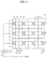
- Figure 4 is an embodiment of the two-dimensional scanning transducer array illustrating a sparse periodic pattern array.
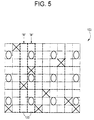
- Figure 5 illustrates the two-dimensional scanning transducer array operating in a three-dimensional (3D) scan mode.
- Figure 5a illustrates an embodiment of a switching arrangement for a bin contained in the two-dimensional scanning transducer array operating in a three-dimensional (3D) scan mode.
- This invention in one embodiment, provides a method for connecting elements such that in the 2D mode, the result using the above example would be an array having 50x5 one-dimensional elements and capable of being steered along the scan direction, where there are 50 "super-elements"which are described in further detail below.
- the remaining 5 super-elements along the elevational direction could be utilized for improved focusing above the level of conventionally available 2D transducer probes.
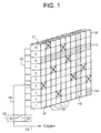
- the first column C1 is configured into a bin B1 having a bin size of 1x10.
- the bin B1 is one element wide in the x-direction and 10 elements high in the y-direction.
- the remaining columns in the array 100 are likewise configured into bins of lx10.
- the array 100 may be configured into any desired bin size of any desired size or configuration.
- Each bin 120 in the array 100 has a system channel 125 and an electronic mode switch 130, integrated in the transducer assembly of a probe, which are associated with a plurality of transducer elements 105 contained within the bin 120.
- the individual mode switch 130 operates as a multiplexer for coupling and energizing select transducer elements 105 for different scanning mode (2D and 3D) operations.
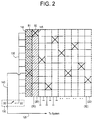
- the operation of the transducer array 100 in relation to generating a two-dimensional (2D) image can further be explained with reference to Figure 2.
- the transducer array 100 of Figure 2 is illustrated as a 10x10 array of individual transducer element 105 configured into bin sizes of lx10.
- the transducer array 100 is constructively transformed into a series of relatively large one-dimensional scanning elements 145.
- the large one-dimensional scanning elements 145 allow for the generation of a quality two-dimensional (2D) image of an object.
- bin B1 will be discussed in detail. However, the principles discussed in relation to bin B1 are equally applicable to one or a combination of the other bins 120 located within the transducer array 100.
- bin B2 adjacent to bin B1, would likewise be transformed from a bin of individual transducer elements 105 into a super-element 145 upon the closure of the respective mode switch associated with bin B2.
- This process is similarly carried out for each bin 120 contained within the array 100, which transforms the array 100 into a series of large one-dimensional elements or super-elements 145, thereby operatively transforming the entire array 100 into a one-dimensional array comprised of large one dimensional element or super-element 145 used for generating two-dimensional (2D) images.
- the transducer array 100 is operated in a sparse array pattern in order to accomplish three-dimensional (3D) volumetric type scanning.
- the sparse binned pattern and the sparse periodic patterns are the sparse binned pattern and the sparse periodic patterns.
- the entire transducer array 100 is divided into bins of size 1x10, with an individual active transducer element 105 (used for 3D imaging) in each bin 120 marked with an "X", with each such transducer element (X) from each of the respective bins 120 being connected to the imaging system through a respective system channel 125 for three-dimensional (3D) imaging.
- the individual transducer elements 105 to be connected in each bin 120, for 3D imaging can be selected at random according to a probability density or by an algorithm which selects, for example, according to an optimization criterion.
- transducer elements 105 marked “X" in each bin 120 may also have corresponding mode switches and channels, represented as 3D/2D ports, which may be activated in order to transform the array 100 into, sparse binned pattern array for three-dimensional (3D) imaging. In one embodiment, this process is similarly carried out for each bin contained within the array 100, to transform the transducer array 100 into sparse binned pattern array for generating three-dimensional (3D) images.
- the transducer array 100 illustrated in Figure 3 is capable of operating in either the 2D or 3D scan mode.
- a mode selection switch 130 is provided for switching between the two-dimensional (2D) scan mode and the three-dimensional (3D) scan mode. Therefore, when the mode switch 130 is positioned in the 2D mode (i.e.: closed position), all of the parallel coupled transducer elements 105 within a bin 120 are activated for 2D imaging. Alternately, when the mode selection switch 130 is positioned in the 3D mode (i.e.: open position), the selected active transducer elements 105 (marked "X") in each bin 120 are activated for 3D imaging.
Landscapes
- Engineering & Computer Science (AREA)
- Physics & Mathematics (AREA)
- Radar, Positioning & Navigation (AREA)
- Remote Sensing (AREA)
- Acoustics & Sound (AREA)
- Health & Medical Sciences (AREA)
- Life Sciences & Earth Sciences (AREA)
- Computer Networks & Wireless Communication (AREA)
- General Physics & Mathematics (AREA)
- Pathology (AREA)
- Surgery (AREA)
- Nuclear Medicine, Radiotherapy & Molecular Imaging (AREA)
- Gynecology & Obstetrics (AREA)
- Radiology & Medical Imaging (AREA)
- Biomedical Technology (AREA)
- Heart & Thoracic Surgery (AREA)
- Medical Informatics (AREA)
- Molecular Biology (AREA)
- Biophysics (AREA)
- Animal Behavior & Ethology (AREA)
- General Health & Medical Sciences (AREA)
- Public Health (AREA)
- Veterinary Medicine (AREA)
- Multimedia (AREA)
- Ultra Sonic Daignosis Equipment (AREA)
- Transducers For Ultrasonic Waves (AREA)
Applications Claiming Priority (2)
| Application Number | Priority Date | Filing Date | Title |
|---|---|---|---|
| US128278 | 1998-08-03 | ||
| US09/128,278 US6279399B1 (en) | 1998-08-03 | 1998-08-03 | Multi-dimensional transducer array apparatus |
Publications (3)
| Publication Number | Publication Date |
|---|---|
| EP0978822A2 true EP0978822A2 (de) | 2000-02-09 |
| EP0978822A3 EP0978822A3 (de) | 2004-02-25 |
| EP0978822B1 EP0978822B1 (de) | 2007-06-06 |
Family
ID=22434530
Family Applications (1)
| Application Number | Title | Priority Date | Filing Date |
|---|---|---|---|
| EP99306160A Expired - Lifetime EP0978822B1 (de) | 1998-08-03 | 1999-08-03 | Multidimensionaler Wandleranordnung |
Country Status (4)
| Country | Link |
|---|---|
| US (1) | US6279399B1 (de) |
| EP (1) | EP0978822B1 (de) |
| JP (1) | JP4404277B2 (de) |
| DE (1) | DE69936247T2 (de) |
Cited By (6)
| Publication number | Priority date | Publication date | Assignee | Title |
|---|---|---|---|---|
| WO2004075165A1 (en) * | 2003-02-14 | 2004-09-02 | Sensant Corporation | Microfabricated ultrasonic transducers with bias polarity beam profile control |
| DE102004026525A1 (de) * | 2004-05-25 | 2005-12-22 | Aesculap Ag & Co. Kg | Verfahren und Vorrichtung zur eingriffslosen Bestimmung markanter Strukturen des menschlichen oder tierischen Körpers |
| FR2923612A1 (fr) * | 2007-11-12 | 2009-05-15 | Super Sonic Imagine Sa | Dispositif d'insonification comprenant un reseau tridimensionnel d'emetteurs disposes en spirale apte a generer un faisceau d'ondes focalisees de grande intensite |
| US7618373B2 (en) | 2003-02-14 | 2009-11-17 | Siemens Medical Solutions Usa, Inc. | Microfabricated ultrasonic transducer array for 3-D imaging and method of operating the same |
| US7635332B2 (en) | 2003-02-14 | 2009-12-22 | Siemens Medical Solutions Usa, Inc. | System and method of operating microfabricated ultrasonic transducers for harmonic imaging |
| US7780597B2 (en) | 2003-02-14 | 2010-08-24 | Siemens Medical Solutions Usa, Inc. | Method and apparatus for improving the performance of capacitive acoustic transducers using bias polarity control and multiple firings |
Families Citing this family (54)
| Publication number | Priority date | Publication date | Assignee | Title |
|---|---|---|---|---|
| JP4632476B2 (ja) * | 2000-03-24 | 2011-02-16 | 株式会社東芝 | 超音波診断装置 |
| JP4643807B2 (ja) * | 2000-07-31 | 2011-03-02 | アロカ株式会社 | 超音波計測装置 |
| US6582367B1 (en) * | 2000-09-15 | 2003-06-24 | Koninklijke Philips Electronics N.V. | 2D ultrasonic transducer array for two dimensional and three dimensional imaging |
| US6419633B1 (en) * | 2000-09-15 | 2002-07-16 | Koninklijke Philips Electronics N.V. | 2D ultrasonic transducer array for two dimensional and three dimensional imaging |
| JP4638622B2 (ja) * | 2001-06-25 | 2011-02-23 | 三井造船株式会社 | リアルタイム3次元超音波映像装置および探触子 |
| US6537220B1 (en) * | 2001-08-31 | 2003-03-25 | Siemens Medical Solutions Usa, Inc. | Ultrasound imaging with acquisition of imaging data in perpendicular scan planes |
| US6676602B1 (en) | 2002-07-25 | 2004-01-13 | Siemens Medical Solutions Usa, Inc. | Two dimensional array switching for beamforming in a volume |
| US7311667B2 (en) * | 2002-09-09 | 2007-12-25 | Siemens Medical Solutions Usa, Inc. | Multiple pattern transducer array and method of use |
| JP4342859B2 (ja) * | 2002-09-30 | 2009-10-14 | 富士フイルム株式会社 | 超音波用探触子及びそれを用いた超音波送受信装置 |
| JP4386683B2 (ja) * | 2002-09-30 | 2009-12-16 | 富士フイルム株式会社 | 超音波送受信装置及び超音波送受信方法 |
| US7564125B2 (en) * | 2002-12-06 | 2009-07-21 | General Electric Company | Electronic array and methods for fabricating same |
| US6792808B1 (en) * | 2003-04-30 | 2004-09-21 | General Electric Company | Ultrasonic inspection method |
| US20040254471A1 (en) * | 2003-06-13 | 2004-12-16 | Andreas Hadjicostis | Miniature ultrasonic phased array for intracardiac and intracavity applications |
| EP1491914B1 (de) * | 2003-06-25 | 2006-10-18 | Aloka Co. Ltd. | Diagnostische ultraschall-bildgebende Vorrichtung mit 2D Schallkopf mit variablen Subarray-Mustern |
| US8316752B2 (en) * | 2003-07-31 | 2012-11-27 | Blastgard Technologies, Inc. | Acoustic shock wave attenuating assembly |
| US7343843B2 (en) * | 2003-07-31 | 2008-03-18 | Blast Gard International | Explosive effect mitigated containers and enclosing devices |
| US20050251127A1 (en) * | 2003-10-15 | 2005-11-10 | Jared Brosch | Miniature ultrasonic transducer with focusing lens for intracardiac and intracavity applications |
| US20050228277A1 (en) * | 2004-04-05 | 2005-10-13 | Siemens Medical Solutions Usa, Inc. | System and method for 2D partial beamforming arrays with configurable sub-array elements |
| JP4470655B2 (ja) * | 2004-09-01 | 2010-06-02 | Jfeスチール株式会社 | 超音波によるスポット溶接部の評価方法及び装置 |
| US20060100522A1 (en) * | 2004-11-08 | 2006-05-11 | Scimed Life Systems, Inc. | Piezocomposite transducers |
| WO2007120890A2 (en) * | 2006-04-13 | 2007-10-25 | The Research Foundation Of State University Of New York | Phased array ultrasound with electronically controlled focal point for assessing bone quality via acoustic topology and wave transmit functions |
| DE102006029435A1 (de) * | 2006-06-20 | 2008-01-10 | BAM Bundesanstalt für Materialforschung und -prüfung | Vorrichtung zur zerstörungsfreien Prüfung von Bauteilen |
| US7874991B2 (en) * | 2006-06-23 | 2011-01-25 | Teratech Corporation | Ultrasound 3D imaging system |
| US7798967B2 (en) | 2006-12-19 | 2010-09-21 | Aloka Co., Ltd. | Ultrasound diagnosis apparatus |
| JP2008237788A (ja) * | 2007-03-29 | 2008-10-09 | Ge Medical Systems Global Technology Co Llc | 超音波撮像装置 |
| JP2009018115A (ja) * | 2007-07-13 | 2009-01-29 | Toshiba Corp | 3次元超音波診断装置 |
| US9339256B2 (en) | 2007-10-01 | 2016-05-17 | Maui Imaging, Inc. | Determining material stiffness using multiple aperture ultrasound |
| US9247926B2 (en) | 2010-04-14 | 2016-02-02 | Maui Imaging, Inc. | Concave ultrasound transducers and 3D arrays |
| JP2009261657A (ja) * | 2008-04-25 | 2009-11-12 | Ge Medical Systems Global Technology Co Llc | 超音波撮像装置 |
| DE102008023218A1 (de) * | 2008-05-10 | 2009-11-12 | Aesculap Ag | Verfahren und Vorrichtung zur Untersuchung eines Körpers mit einem Ultraschallkopf |
| US20120179044A1 (en) | 2009-09-30 | 2012-07-12 | Alice Chiang | Ultrasound 3d imaging system |
| US12102479B2 (en) | 2008-09-15 | 2024-10-01 | Teratech Corporation | Ultrasound 3D imaging system |
| US10080544B2 (en) * | 2008-09-15 | 2018-09-25 | Teratech Corporation | Ultrasound 3D imaging system |
| US9373888B1 (en) * | 2009-03-25 | 2016-06-21 | Raytheon Company | Method and apparatus for reducing sidelobes in large phased array radar with super-elements |
| KR102322776B1 (ko) | 2010-02-18 | 2021-11-04 | 마우이 이미징, 인코포레이티드 | 초음파 이미지를 구성하는 방법 및 이를 위한 다중-개구 초음파 이미징 시스템 |
| US20120071760A1 (en) * | 2010-09-22 | 2012-03-22 | Toshiba Medical Systems Corporation | Reconfigurable medical ultrasound transducer arrays with preprocessing |
| JP6407719B2 (ja) | 2011-12-01 | 2018-10-17 | マウイ イマギング,インコーポレーテッド | ピングベース及び多数開口ドップラー超音波を用いた運動の検出 |
| US9070964B1 (en) * | 2011-12-19 | 2015-06-30 | Raytheon Company | Methods and apparatus for volumetric coverage with image beam super-elements |
| EP2833791B1 (de) | 2012-03-26 | 2022-12-21 | Maui Imaging, Inc. | Verfahren zur verbesserung der ultraschallbildqualität durch anwendung von gewichtungsfaktoren |
| CN104620128B (zh) | 2012-08-10 | 2017-06-23 | 毛伊图像公司 | 多孔径超声探头的校准 |
| CN103676827A (zh) | 2012-09-06 | 2014-03-26 | Ip音乐集团有限公司 | 用于远程控制音频设备的系统和方法 |
| US9958420B2 (en) * | 2013-02-06 | 2018-05-01 | Bwxt Technical Services Group, Inc. | Synthetic data collection method for full matrix capture using an ultrasound array |
| JP6157872B2 (ja) * | 2013-02-20 | 2017-07-05 | 株式会社東芝 | 超音波形状計測装置及び計測方法 |
| BR112015021282B1 (pt) | 2013-03-07 | 2022-01-25 | Koninklijke Philips N.V. | Dispositivo de captura de imagem por ultrassom, sistema de imageamento por ultrassom, kit de captura de imagens por ultrassom, e, método para especificar um estado operacional para um captura de imagem por ultrassom |
| US9379446B1 (en) | 2013-05-01 | 2016-06-28 | Raytheon Company | Methods and apparatus for dual polarized super-element phased array radiator |
| FR3009123B1 (fr) * | 2013-07-24 | 2016-03-11 | Renault Sas | Transducteur ultrasonique et procede de controle par ultrasons d'une zone de soudure. |
| US9883848B2 (en) | 2013-09-13 | 2018-02-06 | Maui Imaging, Inc. | Ultrasound imaging using apparent point-source transmit transducer |
| US10401493B2 (en) | 2014-08-18 | 2019-09-03 | Maui Imaging, Inc. | Network-based ultrasound imaging system |
| US10281571B2 (en) | 2014-08-21 | 2019-05-07 | Raytheon Company | Phased array antenna using stacked beams in elevation and azimuth |
| CN107613878B (zh) | 2015-03-30 | 2021-04-06 | 毛伊图像公司 | 用于检测物体运动的超声成像系统和方法 |
| EP4697068A3 (de) | 2016-01-27 | 2026-04-22 | Maui Imaging, Inc. | Ultraschallbildgebung mit spärlichen arraysonden |
| US11885877B2 (en) * | 2018-05-09 | 2024-01-30 | Dalhousie University | Systems and methods of sparse orthogonal diverging wave ultrasound imaging |
| JP7724853B2 (ja) | 2020-10-21 | 2025-08-18 | マウイ イマギング,インコーポレーテッド | 多数開口超音波を用いた組織の特徴付けのためのシステム及び方法 |
| EP4236811A4 (de) | 2020-11-02 | 2024-10-09 | Maui Imaging, Inc. | Systeme und verfahren zur verbesserung der ultraschallbildqualität |
Family Cites Families (13)
| Publication number | Priority date | Publication date | Assignee | Title |
|---|---|---|---|---|
| US4550606A (en) * | 1982-09-28 | 1985-11-05 | Cornell Research Foundation, Inc. | Ultrasonic transducer array with controlled excitation pattern |
| US4694434A (en) | 1984-06-12 | 1987-09-15 | Von Ramm Olaf T | Three-dimensional imaging system |
| JP2789234B2 (ja) * | 1989-10-02 | 1998-08-20 | 株式会社日立メディコ | 超音波診断装置 |
| JP3090718B2 (ja) * | 1990-07-11 | 2000-09-25 | 株式会社東芝 | 超音波診断装置 |
| US5269309A (en) * | 1991-12-11 | 1993-12-14 | Fort J Robert | Synthetic aperture ultrasound imaging system |
| US5842473A (en) * | 1993-11-29 | 1998-12-01 | Life Imaging Systems | Three-dimensional imaging system |
| US5490512A (en) * | 1994-06-16 | 1996-02-13 | Siemens Medical Systems, Inc. | Elevation direction focusing in ultrasound transducer arrays |
| US5677491A (en) | 1994-08-08 | 1997-10-14 | Diasonics Ultrasound, Inc. | Sparse two-dimensional transducer array |
| US5537367A (en) | 1994-10-20 | 1996-07-16 | Lockwood; Geoffrey R. | Sparse array structures |
| US5546807A (en) | 1994-12-02 | 1996-08-20 | Oxaal; John T. | High speed volumetric ultrasound imaging system |
| US5787049A (en) * | 1995-11-07 | 1998-07-28 | Bates; Kenneth N. | Acoustic wave imaging apparatus and method |
| US5938612A (en) * | 1997-05-05 | 1999-08-17 | Creare Inc. | Multilayer ultrasonic transducer array including very thin layer of transducer elements |
| US5934288A (en) * | 1998-04-23 | 1999-08-10 | General Electric Company | Method and apparatus for displaying 3D ultrasound data using three modes of operation |
-
1998
- 1998-08-03 US US09/128,278 patent/US6279399B1/en not_active Expired - Fee Related
-
1999
- 1999-08-02 JP JP21843999A patent/JP4404277B2/ja not_active Expired - Fee Related
- 1999-08-03 DE DE69936247T patent/DE69936247T2/de not_active Expired - Lifetime
- 1999-08-03 EP EP99306160A patent/EP0978822B1/de not_active Expired - Lifetime
Cited By (10)
| Publication number | Priority date | Publication date | Assignee | Title |
|---|---|---|---|---|
| WO2004075165A1 (en) * | 2003-02-14 | 2004-09-02 | Sensant Corporation | Microfabricated ultrasonic transducers with bias polarity beam profile control |
| US7087023B2 (en) | 2003-02-14 | 2006-08-08 | Sensant Corporation | Microfabricated ultrasonic transducers with bias polarity beam profile control and method of operating the same |
| US7618373B2 (en) | 2003-02-14 | 2009-11-17 | Siemens Medical Solutions Usa, Inc. | Microfabricated ultrasonic transducer array for 3-D imaging and method of operating the same |
| US7635332B2 (en) | 2003-02-14 | 2009-12-22 | Siemens Medical Solutions Usa, Inc. | System and method of operating microfabricated ultrasonic transducers for harmonic imaging |
| US7780597B2 (en) | 2003-02-14 | 2010-08-24 | Siemens Medical Solutions Usa, Inc. | Method and apparatus for improving the performance of capacitive acoustic transducers using bias polarity control and multiple firings |
| DE102004026525A1 (de) * | 2004-05-25 | 2005-12-22 | Aesculap Ag & Co. Kg | Verfahren und Vorrichtung zur eingriffslosen Bestimmung markanter Strukturen des menschlichen oder tierischen Körpers |
| US7691062B2 (en) | 2004-05-25 | 2010-04-06 | Aesculap Ag | Method and apparatus for the non-invasive determination of prominent structures of the body of a human being or an animal |
| FR2923612A1 (fr) * | 2007-11-12 | 2009-05-15 | Super Sonic Imagine Sa | Dispositif d'insonification comprenant un reseau tridimensionnel d'emetteurs disposes en spirale apte a generer un faisceau d'ondes focalisees de grande intensite |
| WO2009062977A1 (en) * | 2007-11-12 | 2009-05-22 | Super Sonic Imagine | An insonification device that includes a three-dimensional network of emitters arranged in at least two concentric spirals, which are designed to generate a beam of high- intens i ty focussed waves |
| US8649242B2 (en) | 2007-11-12 | 2014-02-11 | Super Sonic Imagine | Insonification device that includes a three-dimensional network of emitters arranged in at least two concentric spirals, which are designed to generate a beam of high-intensity focussed waves |
Also Published As
| Publication number | Publication date |
|---|---|
| JP4404277B2 (ja) | 2010-01-27 |
| EP0978822A3 (de) | 2004-02-25 |
| DE69936247D1 (de) | 2007-07-19 |
| EP0978822B1 (de) | 2007-06-06 |
| US6279399B1 (en) | 2001-08-28 |
| JP2000069593A (ja) | 2000-03-03 |
| DE69936247T2 (de) | 2008-02-07 |
Similar Documents
| Publication | Publication Date | Title |
|---|---|---|
| EP0978822B1 (de) | Multidimensionaler Wandleranordnung | |
| US7322936B2 (en) | Ultrasound diagnosis apparatus | |
| EP1491913B1 (de) | Diagnostische ultraschall-bildgebende Vorrichtung mit einem 2D Schallkopf mit variablen Subarrays | |
| US5186175A (en) | Ultrasonic diagnostic apparatus | |
| US4528854A (en) | Phased-array receiver | |
| US8177718B2 (en) | Linear array ultrasound transducer with variable patch boundaries | |
| EP3376253A2 (de) | 3d-ultraschallbildgebungssystem | |
| JP3977826B2 (ja) | 超音波診断装置 | |
| US6821251B2 (en) | Multiplexer for connecting a multi-row ultrasound transducer array to a beamformer | |
| US20050228277A1 (en) | System and method for 2D partial beamforming arrays with configurable sub-array elements | |
| CN101031816A (zh) | 微波束形成换能器结构 | |
| WO2007099473A1 (en) | Linear array ultrasound transducer with microbeamformer | |
| US20090099454A1 (en) | Equal phase two-dimensional array probe | |
| JP2005034634A (ja) | 超音波診断装置 | |
| US7798967B2 (en) | Ultrasound diagnosis apparatus | |
| JP2006506159A (ja) | 超音波画像化システムにおいてマルチラインビームからbフローデータとbモードデータとを取得する方法および装置 | |
| EP1936404B1 (de) | Diagnostisches Ultraschallgerät | |
| CN112368600B (zh) | 通过稀疏采样进行的超声成像和相关联的设备、系统和方法 | |
| CA2376301A1 (en) | Improved volumetric ultrasound imaging with a thinned array | |
| CN109381218B (zh) | 一种三维超声成像方法及装置 | |
| KR100816825B1 (ko) | 변환자 그룹화 스위치를 이용한 2차원 배열 변환자의 집속장치 및 3차원 초음파 영상 형성 시스템 | |
| JP2019154977A (ja) | 超音波診断装置 | |
| JP5345481B2 (ja) | 超音波診断装置 | |
| US20250110237A1 (en) | Method for operating a scanning acoustic microscope | |
| JP5409207B2 (ja) | 超音波診断装置 |
Legal Events
| Date | Code | Title | Description |
|---|---|---|---|
| PUAI | Public reference made under article 153(3) epc to a published international application that has entered the european phase |
Free format text: ORIGINAL CODE: 0009012 |
|
| AK | Designated contracting states |
Kind code of ref document: A2 Designated state(s): AT BE CH CY DE DK ES FI FR GB GR IE IT LI LU MC NL PT SE |
|
| AX | Request for extension of the european patent |
Free format text: AL;LT;LV;MK;RO;SI |
|
| PUAL | Search report despatched |
Free format text: ORIGINAL CODE: 0009013 |
|
| AK | Designated contracting states |
Kind code of ref document: A3 Designated state(s): AT BE CH CY DE DK ES FI FR GB GR IE IT LI LU MC NL PT SE |
|
| AX | Request for extension of the european patent |
Extension state: AL LT LV MK RO SI |
|
| 17P | Request for examination filed |
Effective date: 20040825 |
|
| AKX | Designation fees paid |
Designated state(s): DE NL |
|
| 17Q | First examination report despatched |
Effective date: 20050407 |
|
| GRAP | Despatch of communication of intention to grant a patent |
Free format text: ORIGINAL CODE: EPIDOSNIGR1 |
|
| GRAS | Grant fee paid |
Free format text: ORIGINAL CODE: EPIDOSNIGR3 |
|
| GRAA | (expected) grant |
Free format text: ORIGINAL CODE: 0009210 |
|
| AK | Designated contracting states |
Kind code of ref document: B1 Designated state(s): DE NL |
|
| REF | Corresponds to: |
Ref document number: 69936247 Country of ref document: DE Date of ref document: 20070719 Kind code of ref document: P |
|
| PGFP | Annual fee paid to national office [announced via postgrant information from national office to epo] |
Ref country code: NL Payment date: 20070824 Year of fee payment: 9 |
|
| PLBE | No opposition filed within time limit |
Free format text: ORIGINAL CODE: 0009261 |
|
| STAA | Information on the status of an ep patent application or granted ep patent |
Free format text: STATUS: NO OPPOSITION FILED WITHIN TIME LIMIT |
|
| 26N | No opposition filed |
Effective date: 20080307 |
|
| NLV4 | Nl: lapsed or anulled due to non-payment of the annual fee |
Effective date: 20090301 |
|
| PG25 | Lapsed in a contracting state [announced via postgrant information from national office to epo] |
Ref country code: NL Free format text: LAPSE BECAUSE OF NON-PAYMENT OF DUE FEES Effective date: 20090301 |
|
| PGFP | Annual fee paid to national office [announced via postgrant information from national office to epo] |
Ref country code: DE Payment date: 20110830 Year of fee payment: 13 |
|
| PG25 | Lapsed in a contracting state [announced via postgrant information from national office to epo] |
Ref country code: DE Free format text: LAPSE BECAUSE OF NON-PAYMENT OF DUE FEES Effective date: 20130301 |
|
| REG | Reference to a national code |
Ref country code: DE Ref legal event code: R119 Ref document number: 69936247 Country of ref document: DE Effective date: 20130301 |