EP0979023B1 - Elekrische Versorgungseinrichtung für eine Widerstandsheizschicht einer Heizdecke und heizbares Rettungssystem - Google Patents
Elekrische Versorgungseinrichtung für eine Widerstandsheizschicht einer Heizdecke und heizbares Rettungssystem Download PDFInfo
- Publication number
- EP0979023B1 EP0979023B1 EP99112565A EP99112565A EP0979023B1 EP 0979023 B1 EP0979023 B1 EP 0979023B1 EP 99112565 A EP99112565 A EP 99112565A EP 99112565 A EP99112565 A EP 99112565A EP 0979023 B1 EP0979023 B1 EP 0979023B1
- Authority
- EP
- European Patent Office
- Prior art keywords
- resistance heating
- heating layer
- power supply
- electrical power
- batteries
- Prior art date
- Legal status (The legal status is an assumption and is not a legal conclusion. Google has not performed a legal analysis and makes no representation as to the accuracy of the status listed.)
- Expired - Lifetime
Links
Images

Classifications
-
- H—ELECTRICITY
- H05—ELECTRIC TECHNIQUES NOT OTHERWISE PROVIDED FOR
- H05B—ELECTRIC HEATING; ELECTRIC LIGHT SOURCES NOT OTHERWISE PROVIDED FOR; CIRCUIT ARRANGEMENTS FOR ELECTRIC LIGHT SOURCES, IN GENERAL
- H05B3/00—Ohmic-resistance heating
-
- H—ELECTRICITY
- H05—ELECTRIC TECHNIQUES NOT OTHERWISE PROVIDED FOR
- H05B—ELECTRIC HEATING; ELECTRIC LIGHT SOURCES NOT OTHERWISE PROVIDED FOR; CIRCUIT ARRANGEMENTS FOR ELECTRIC LIGHT SOURCES, IN GENERAL
- H05B3/00—Ohmic-resistance heating
- H05B3/20—Heating elements having extended surface area substantially in a two-dimensional [2D] plane, e.g. plate-heater
- H05B3/34—Heating elements having extended surface area substantially in a two-dimensional [2D] plane, e.g. plate-heater flexible, e.g. heating nets or webs
-
- H—ELECTRICITY
- H05—ELECTRIC TECHNIQUES NOT OTHERWISE PROVIDED FOR
- H05B—ELECTRIC HEATING; ELECTRIC LIGHT SOURCES NOT OTHERWISE PROVIDED FOR; CIRCUIT ARRANGEMENTS FOR ELECTRIC LIGHT SOURCES, IN GENERAL
- H05B2203/00—Aspects relating to Ohmic resistive heating covered by group H05B3/00
- H05B2203/002—Heaters using a particular layout for the resistive material or resistive elements
- H05B2203/007—Heaters using a particular layout for the resistive material or resistive elements using multiple electrically connected resistive elements or resistive zones
-
- H—ELECTRICITY
- H05—ELECTRIC TECHNIQUES NOT OTHERWISE PROVIDED FOR
- H05B—ELECTRIC HEATING; ELECTRIC LIGHT SOURCES NOT OTHERWISE PROVIDED FOR; CIRCUIT ARRANGEMENTS FOR ELECTRIC LIGHT SOURCES, IN GENERAL
- H05B2203/00—Aspects relating to Ohmic resistive heating covered by group H05B3/00
- H05B2203/011—Heaters using laterally extending conductive material as connecting means
-
- H—ELECTRICITY
- H05—ELECTRIC TECHNIQUES NOT OTHERWISE PROVIDED FOR
- H05B—ELECTRIC HEATING; ELECTRIC LIGHT SOURCES NOT OTHERWISE PROVIDED FOR; CIRCUIT ARRANGEMENTS FOR ELECTRIC LIGHT SOURCES, IN GENERAL
- H05B2203/00—Aspects relating to Ohmic resistive heating covered by group H05B3/00
- H05B2203/013—Heaters using resistive films or coatings
Definitions
- the invention relates to an electrical supply device, for an essentially of a flat, flexible Carbon fiber fabric formed a resistance heating layer Electric blanket, with at least one accumulator as well as a heatable one Rescue system.
- a heating blanket is known from DE 196 42 037 A1, at which is the flat electrically operable resistance heating layer of a flexible, essentially only carbon fiber existing layer is formed.
- electrical Supply device for the resistance heating layer can for example a vehicle battery with a supply voltage of about 12 volts.
- the well-known electric blanket can preferably be used in the medical field. It is used to maintain body temperature of patients, for example during an operation or also of accident victims at the scene of the accident. Especially during one Surgery can reduce body temperature due to anesthesia decrease significantly. For longer operations they are Evidently hypothermic patient. This hypothermia can the cause of common infections. Moreover the recovery phase after surgery is significantly extended.
- the known electric blanket is transverse to its longitudinal extent divided into several electric blanket elements, the transversely extending heated ceiling elements laterally through a Longitudinal bar are connected by which also the power supply lines can be routed. hereby on the one hand it is ensured that during the operation or during the intervention on the body the corresponding part of the body exposed by folding away a heating blanket element can be, so that the attending doctor unhindered Has access to that part of the body. On the other hand, hypothermia of the patient through which the patient's body still covering heating blanket elements prevented.
- the object of the invention is an electrical supply device for the resistance heating layer one preferred for use in the medical field Electric blanket, in the case of faults and injuries to the resistance heating layer
- the patient and the treating doctor remain safe, as well as an easy to use to create a heatable rescue system.
- a heating blanket at least two batteries are provided, the are connectable to the resistance heating layer.
- the electrical supply to the resistance heating layer happens exclusively by at least one of the accumulators.
- the accumulator or accumulators, which are used to supply power to the resistance heating layer is or are connected, are from the network or another power generator, e.g. B. generator, and absolutely separated from ground. It is an electrical one Supply of the resistance heating layer, at which potential freedom is guaranteed is. This is also in the event of malfunctions and / or injuries to the electrical lines and the resistance heating layer endangers the patient or the treating person Doctor avoided.
- the entire electrical supply is completely separated from connections to the supply network, another power generator and ground.
- the other or the other accumulator (s) to a charging device be connectable or connected.
- the electrical connection between the batteries and the resistance heating layer interrupted. this happens by an on-off switch, which provides an absolute separation between the resistance heating layer and the accumulators during the switching process.
- Changeover switches that can be operated electromagnetically (relays) are used for switching. By disconnecting the supply circuit during the switching process Sparking at the switch contacts and bouncing of the switch contacts prevented. The supply circuit remains switched off for a few seconds, for example, so that sparking and bouncing are reliably prevented.
- the batteries can alternate with the resistance layer and the charger.
- a setpoint temperature can be specified for temperature control, with reaching the target temperature by temperature sensors distributed in the resistance heating layer is detected.
- the temperature control can be done with the help of a central computer device (Microprocessor). This can with respect to the target temperature and other parameters such as programmable for the respective switching temperature his.
- the parameters can be displayed on a display or monitor become. During operation, the temperature sensors measured temperatures are displayed.
- the device can be protected by fuses be protected in the event of short circuits.
- the electronic one Control device for temperature control subjected to a self-test. in this connection the parameters are displayed and it can be checked whether these parameters, especially the target temperature is properly set.
- the heating process can start regardless of whether or not the resistance heating layer connected accumulator or accumulators connected to the charging device are or not.
- the target temperature e.g. 37.5 ° C, is controlled maintain this temperature.
- the accuracy in temperature detection is approximately at ⁇ 0.3 ° C.
- the central control device e.g. Microprocessor
- Signals from the respective temperature sensors, which are in the resistance heating layer are installed, signals, which when scanning the battery voltage be obtained, as well as a signal which indicates whether the supply voltage (approx. 12 volts) is present.
- the accumulator or accumulators which are are not connected to the resistance heating layer during the supply operation the other accumulator or the other accumulators charged, if this is required. If the capacity of the battery in the utility mode is exhausted, the central control device (microprocessor) switches over causes so that the exhausted accumulator or the exhausted accumulators be connected to the charger. The other or the others charged batteries are then used to power the resistance heating layer connected to this, the newly connected accumulator or the newly connected batteries from the network or a power generator as well are absolutely separated from the mass. The exhausted accumulator or the exhausted Accumulators are being charged. The switchover is preferably dependent of the remaining capacity, preferably approximately 25% of the remaining capacity of the respective utility company located accumulator.
- Lead accumulators with a high energy density are preferably used. Two identical accumulators are preferably used. With a total power requirement of approx. 300 watts for the heating phase and approx. 100 watts for the maintenance phase the capacity of these batteries will be between 8 and 24 amp hours preferred at 12 volts. Such batteries are commercially available and weigh approx. 3 to 10 kg. As a result, a supply operation of each accumulator be maintained for about 30 minutes. With fully charged accumulators is therefore without external supply a heating blanket supply of at least one hour guaranteed.
- a charger is preferably used as the charging device whose function is optimized for quick charging. The charger can also by another 12 volt supply device, e.g. over the cigarette lighter plug of a vehicle.
- the electric blanket can be operated on at the operating table be grounded. Due to the temperature control, an optimal function adjustment, e.g. Temperature setting reached.
- an optimal function adjustment e.g. Temperature setting reached.
- the controlled electrical supply device can be trained to meet MedGV and EMV.
- the wiring and the supply of the resistance heating layer of the electric blanket which can be designed in such a way as that known from DE 196 42 037 A1 Electric blanket, preferably done with highly flexible silicone-insulated cables.
- the Contacting of the resistance heating layer with the supply conductors takes place in a preferred manner Way with the aid of electrically conductive flexible tapes, in particular made of metal, e.g. Copper with elastic threads and high tensile force in the textile-like resistance heating layer are sewn in.
- the respective band is also, in particular on both sides provided with a temperature-resistant and non-water-soluble contact paste. To this In this way, a very low contact resistance between copper strips is achieved and the carbon fiber fabric of the resistance heating layer.
- the width of the copper tape is approx. 8 mm.
- the contacting of the resistance heating layer can also be done using a contacting paste, silver paste in particular, which are made along two opposite one another Edge strips of the resistance heating layer, for example by impregnation, impregnation or similar; is introduced into the carbon fiber fabric.
- the electrical supply device can also be used for a heatable one Rescue system can be used, which in such an inventive way is formed that a blanket is arranged over a thermally insulated lying surface can be, which on its inner side assigned to the lying surface at least one Has resistance heating layer. It can, for example, in the longitudinal direction of the ceiling seen, three resistance heating layers can be provided on the inside of the ceiling.
- the lying surface and the ceiling can be connected to each other so that the ceiling can be folded over the lying surface.
- a support device be provided. Due to the ceiling with the resistance heating layer, can a patient lying on the lying surface during transport or during his Treatment should be kept at normal body temperature.
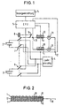
- FIG. 1 shows a block diagram of an exemplary embodiment of the electrical supply device.
- This has two accumulators 2 and 3, which alternately a resistance heating layer 1 of an electric blanket can be connected.
- the resistance heating layer can be divided into several heating layer elements as it is made from DE 196 42 037 A1 is known.
- the resistance heating layers 1 of the various Heating elements are in parallel with the supply voltage, approx. 12 volts, of a respective one Accumulator 2, 3 connected.
- there is the battery 2 in the supply mode, while the battery 3 in the charging mode is connected to a charging device 4. Switching between utilities and charging is carried out by means of an electromagnetically controlled changeover switch 6, 7, a relay coil 8 being provided for both or for the respective changeover switch can be.
- Fig. 1 is an embodiment with two identical batteries, in particular Lead accumulators of high energy density, shown. If necessary, can be used for supply the electric blanket also has more accumulators connected to one or more at the same time Electric blankets are connected, with the remaining batteries in charging mode are connected to the charging device 4.
- a temperature sensor 10 is assigned to each resistance heating layer 1 of a heating element.
- the respective temperature sensors 10 are equipped with an electronic control device (CPU, microprocessor) connected.
- the temperature sensors 10 deliver to the temperature the resistance heating layer 1 proportional temperature signals to the central control device 5.
- In the central control device 5 is also a target temperature to which the resistance heating layer 1 is to be heated, entered. This target temperature is, for example, 37.5 ° C.
- To monitor the utility company each connected to the resistance heating layer 1 accumulator (in the figure of the accumulator 2) are tapping points 12, 13 in the supply circuit for the resistance heating layer 1 or resistance heating layers 1 are provided, for example the respective supply voltage supplied by the accumulator can be tapped can. This also allows an indication of the remaining capacity of the Gain accumulator located utility company.
- the corresponding signal is also supplied to the central control device 5.
- Power electronics are also located in each resistance heating layer 1 11, which is controlled by the central control device 5. Through the power electronics 11, the supply current is adjusted by that of the connected Accumulator is supplied to the resistance heating layer 1.
- the power electronics 11 is carried out by the central control device 5 in dependence from the temperature measured by the temperature sensor 10.
- the power electronics 11 can have an electronic circuit breaker for this purpose, which depends from the measured temperature of the resistance heating layer 1 on and off becomes.
- the central control device 5 delivers a corresponding to the relay coil 8 Switching. Before initiating the switching process, however, is by Opening an on-off switch 9, the supply device consisting of the accumulators 2, 3 separated from the resistance heating layers 1. As soon as the switching process is executed, i.e.
- a flexible, electrically conductive tape in particular made of copper, connected to an electrical line 18 of the wiring, for example by soldering.
- This band 17 is made with a carbon fiber fabric in particular Resistance heating layer 1 sewn. Elastic sewing threads 16 are used for this.
- the tape is double-sided with a temperature-resistant and not water-soluble Provide contact paste 15.
- the resistance heating layer 1 is on both sides of the coated Tape so that the coated tape into the carbon fiber fabric of the resistance heating layer 1 is sewn in. To do this, the resistance heating layer at the edge around that coated with the contact paste 15. Volume 17 are flipped.
- FIG. 4 shows a further exemplary embodiment for the contacting of the resistance heating layer 1 shown.
- the two Contact strips 19 are connected to the electrical conductors 18 in a known manner electrically connected.
- the electrical conductors 18 are in a lateral cable guide 26 guided along the resistance heating layers 1, in the one shown in FIG Exemplary rescue blanket are three flat resistance heating layers 1 side by side on the underside of the ceiling.
- This blanket can be a foldable Blanket 28 ( Figure 5), an emergency blanket 20.
- the emergency blanket 20 has a lying surface 22 made of a soft material exists, and is thermally isolating.
- the lying surface 22 is on an insulation layer Outer shell 21 of the emergency blanket applied.
- the outer shell 21 consists of a waterproof, washable, tearproof, windproof and blood-resistant material.
- the outer shell 21 is designed as a continuous web and has such a width that also the ceiling 28, which has the resistance heating layers 1 ( Figure 3), is included.
- the blanket 28 in the direction of a Arrow 27 can be folded down and arranged over the lying surface 22.
- the outer shell 21 of the blanket 28 and the outer shell 21 of the lying surface 22 can also by another material foldable in the longitudinal direction of the emergency blanket 20 be connected.
- the resistance heating layers 1 can have envelopes 25 which are skin-friendly, temperature neutral, opaque, blood resistant, autoclavable and sterilizable as well as at higher temperature (e.g. 95 ° C) are washable.
- the respective resistance heating layers 1 have the temperature sensor 10, which in the manner shown in Figure 1 are connected to the electrical supply device.
- the total width of the emergency blanket 20 can be approximately 140 cm.
- the length of a respective segment of the resistance layers (FIG. 3) is approximately 67 cm and the Width 44 cm.
- Velcro strips 23 can be provided on the inside of the outer cover 21. through of the Velcro strips 23 can the covered resistance heating layers 1 on the inside the outer shell 21 to be attached.
- the lying surface 22 can also have Velcro strips.
- the ceiling 28 can at its outer edge closure means, not shown which have closure means in the region of the outer edge of the lying surface 22 serve to fix the folded ceiling 28 over the lying surface 22.
- the power supply of the resistance heating layer or resistance heating layers 1 3 and 5, with the aid of one or more accumulators, optionally with a control device, as shown in FIG. 1 is, or by an existing generator in an emergency vehicle, e.g. B. alternator or the vehicle battery.
Landscapes
- Surface Heating Bodies (AREA)
- Resistance Heating (AREA)
- Control Of Resistance Heating (AREA)
Description
- Fig. 1
- ein Blockschaltbild eines Ausführungsbeispiels;
- Fig. 2
- eine Ausführungsform zur Kontaktierung der Widerstandsheizschicht;
- Fig. 3
- eine Unterseite einer Rettungsdecke, welche bei einem Rettungssystem zum Einsatz kommen kann;
- Fig. 4
- eine weitere Ausführungsform zur Kontaktierung der Widerstandsheizschicht;
- Fig. 5
- ein Ausführungsbeispiel für ein heizbares Rettungssystem, in Form einer faltbaren Rettungsdecke.
- 1
- Widerstandsheizschicht
- 2
- Akkumulator
- 3
- Akkumulator
- 4
- Aufladeeinrichtung
- 5
- Zentrale Steuereinrichtung
- 6
- Umschalter
- 7
- Umschalter
- 8
- Relaisspule
- 9
- Ein-Ausschalter
- 10
- Temperaturfühler
- 11
- Leistungselektronik
- 12
- Abgriff
- 13
- Abgriff
- 14
- Anzeigeeinrichtung
- 15
- Kontaktpaste
- 16
- Nähfäden
- 17
- elektrisch leitfähiges Band
- 18
- elektrische Leitung
- 19
- Kontaktierungsstreifen
- 20
- Rettungsdecke
- 21
- Außenhülle
- 22
- Liegefläche
- 23
- Klettbänder
- 24
- Trageinrichtung
- 25
- Hülle
- 26
- Kabelführung
- 27
- Klapprichtung
- 28
- Decke
- 29
- Festigungsstrang
Claims (9)
- Elektrische Versorgungseinrichtung für eine im wesentlichen von einem flächigen flexiblen Kohlefasergewebe gebildeten Widerstandsheizschicht einer Heizdecke, mit wenigstens einem Akkumulator, dadurch gekennzeichnet, dass wenigstens zwei Akkumulatoren (2, 3) an die Widerstandsheizschicht (1) anschließbar sind, wobei die elektrische Versorgung der Widerstandsheizschicht (1) ausschließlich durch wenigstens einen der Akkumulatoren (2, 3) erfolgt, welcher vom Netz oder einem Stromerzeuger sowie Masse absolut getrennt ist, während der andere bzw. die anderen Akkumulatoren an eine Aufladeeinrichtung (4) anschließbar oder angeschlossen ist bzw. sind, dass an die Pole der Akkumulatoren (2, 3) Umschalter (6, 7) angeschlossen sind, welche die Akkumulatoren (2, 3) wechselweise mit der Widerstandsheizschicht (1) und der Aufladeeinrichtung (4) verbinden und dass eine Ein-Ausschalteinrichtung (9) vorgesehen ist, welche beim Umschalten der Akkumulatoren (2, 3) zwischen Auflade- und Versorgungsbetrieb die elektrische Verbindung zwischen den Akkumulatoren (2, 3) und der Widerstandsheizschicht (1) unterbricht.
- Elektrische Versorgungseinrichtung nach Anspruch 1, dadurch gekennzeichnet, daß die Umschaltung in Abhängigkeit von der Restkapazität, vorzugsweise bei 25% der Restkapazität erfolgt.
- Elektrische Versorgungseinrichtung nach Anspruch 1 oder 2, dadurch gekennzeichnet, daß die Heizdecke geerdet ist.
- Elektrische Versorgungseinrichtung nach einem der Ansprüche 1 bis 3, dadurch gekennzeichnet, daß zur Kontaktierung in die Widerstandsheizschicht (1) ein elektrisch leitendes flexibles Band (17), welches beidseitig mit Kontaktpaste beschichtet ist, eingenäht ist.
- Elektrische Versorgungseinrichtung nach Anspruch 4, dadurch gekennzeichnet, daß ein Randbereich der Widerstandsheizschicht (1) beidseitig um das elektrisch leitende Band (17) gelegt ist.
- Elektrische Versorgungseinrichtung nach einem der Ansprüche 1 bis 3, dadurch gekennzeichnet, daß zur Kontaktierung der Widerstandsheizschicht (1) in das Kohlefasergewebe der Widerstandsheizschicht (1) eine elektrische Kontaktierungspaste, insbesondere Silberpaste, entlang eines Kontaktierungsstreifens (19) eingebracht ist.
- Heizbares Rettungssystem mit wenigstens einer, insbesondere durch eine elektrische Versorgungseinrichtung gemäß einem der Ansprüche 1 bis 6 beheizbaren und von einem flächigen, flexiblen Kohlefasergewebe gebildeten Widerstandsheizschicht, gekennzeichnet durch eine termisch isolierte Liegefläche (22) und einer über der Liegefläche angeordneten Decke (28), welche an ihrer der Liegefläche (22) zugewandten Innenseite die wenigstens eine Widerstandsheizschicht (1) aufweist.
- Heizbares Rettungssystem nach Anspruch 7, dadurch gekennzeichnet, daß die Decke (28) auf die Liegefläche (22) klappbar ist.
- Heizbares Rettungssystem nach Anspruch 7 oder 8, dadurch gekennzeichnet, daß an der Liegefläche (22) eine Trageinrichtung (24) vorgesehen ist.
Applications Claiming Priority (2)
| Application Number | Priority Date | Filing Date | Title |
|---|---|---|---|
| DE19831023 | 1998-07-10 | ||
| DE19831023A DE19831023A1 (de) | 1998-07-10 | 1998-07-10 | Elektrische Versorgungseinrichtung für eine Widerstandsheizschicht einer Heizdecke und heizbares Rettungssystem |
Publications (2)
| Publication Number | Publication Date |
|---|---|
| EP0979023A1 EP0979023A1 (de) | 2000-02-09 |
| EP0979023B1 true EP0979023B1 (de) | 2002-10-09 |
Family
ID=7873668
Family Applications (1)
| Application Number | Title | Priority Date | Filing Date |
|---|---|---|---|
| EP99112565A Expired - Lifetime EP0979023B1 (de) | 1998-07-10 | 1999-07-01 | Elekrische Versorgungseinrichtung für eine Widerstandsheizschicht einer Heizdecke und heizbares Rettungssystem |
Country Status (3)
| Country | Link |
|---|---|
| EP (1) | EP0979023B1 (de) |
| AT (1) | ATE226007T1 (de) |
| DE (2) | DE19831023A1 (de) |
Cited By (1)
| Publication number | Priority date | Publication date | Assignee | Title |
|---|---|---|---|---|
| US12351977B2 (en) | 2019-03-15 | 2025-07-08 | Ember Technologies, Inc. | Actively heated or cooled garments or footwear |
Families Citing this family (5)
| Publication number | Priority date | Publication date | Assignee | Title |
|---|---|---|---|---|
| DE102006006201B4 (de) * | 2006-02-09 | 2013-05-29 | Beurer Gmbh | Wärmegerät mit einem schmiegsamen Heizkörper |
| DE102013203584B4 (de) * | 2013-03-01 | 2016-01-07 | Beiersdorf Ag | Heizelement mit flächiger, Wärme entwickelnder Schicht, Pflaster mit Heizelement und Verfahren zur Herstellung eines Heizelements |
| US10925119B2 (en) | 2015-01-12 | 2021-02-16 | Laminaheat Holding Ltd. | Fabric heating element |
| CA3001643A1 (en) | 2015-10-19 | 2017-04-27 | Laminaheat Holding Ltd. | Laminar heating elements with customized or non-uniform resistance and/or irregular shapes, and processes for manufacture |
| USD911038S1 (en) | 2019-10-11 | 2021-02-23 | Laminaheat Holding Ltd. | Heating element sheet having perforations |
Family Cites Families (3)
| Publication number | Priority date | Publication date | Assignee | Title |
|---|---|---|---|---|
| EP0435317A3 (en) * | 1989-12-28 | 1992-06-17 | Kabushiki Kaisha Toshiba | Personal computer for performing charge and switching control of different types of battery packs |
| US5264777A (en) * | 1991-07-24 | 1993-11-23 | Ample Power Company | System for isolating commonly charged batteries |
| DE19642037C2 (de) * | 1996-10-11 | 1999-04-15 | Thermamed Gmbh | Heizdecke |
-
1998
- 1998-07-10 DE DE19831023A patent/DE19831023A1/de not_active Withdrawn
-
1999
- 1999-07-01 AT AT99112565T patent/ATE226007T1/de not_active IP Right Cessation
- 1999-07-01 DE DE59903006T patent/DE59903006D1/de not_active Expired - Fee Related
- 1999-07-01 EP EP99112565A patent/EP0979023B1/de not_active Expired - Lifetime
Cited By (1)
| Publication number | Priority date | Publication date | Assignee | Title |
|---|---|---|---|---|
| US12351977B2 (en) | 2019-03-15 | 2025-07-08 | Ember Technologies, Inc. | Actively heated or cooled garments or footwear |
Also Published As
| Publication number | Publication date |
|---|---|
| DE19831023A1 (de) | 2000-01-13 |
| DE59903006D1 (de) | 2002-11-14 |
| ATE226007T1 (de) | 2002-10-15 |
| EP0979023A1 (de) | 2000-02-09 |
Similar Documents
| Publication | Publication Date | Title |
|---|---|---|
| DE2803275C3 (de) | Fernschalteinrichtung zum Schalten eines monopolaren HF-Chirurgiegerätes | |
| EP0201103B1 (de) | Überwachungsvorrichtung für ein Hochfrequenz-Chirurgiegerät | |
| DE4339049C2 (de) | Einrichtung zur Konfiguration chirurgischer Systeme | |
| DE69836816T2 (de) | Elektrode mit gesteuertem stromfluss | |
| EP0316469B1 (de) | Hochfrequenz-Chirugiegerät zum Schneiden und/oder Koagulieren biologischer Gewebe | |
| DE69301335T2 (de) | Sicherheitsvorrichtung für die Elektrochirurgie oder das Schweissen | |
| DE69829533T2 (de) | Vorrichtung zur Verabreichung von Medikamenten auf verschiedene Stellen | |
| EP0984664B1 (de) | Implantierbare Vorrichtung mit einer eine Empfangsspule aufweisenden Ladestromeinspeiseanordnung | |
| DE69829336T2 (de) | Vorrichtung und Verfahren zur Behandlung von Körpergewebe | |
| EP2537479B1 (de) | Steuerung eines medizinischen Geräts in Abhängigkeit von der Neutralektrodenimpedanz | |
| EP1106033B1 (de) | Widerstandsflächen-heizelement | |
| DE3225237A1 (de) | Vorrichtung zum aufheben von leckstroemen in der elektrochirurgie | |
| EP2044882A1 (de) | Vorrichtung zur Erfassung und Übertragung von elektrischen Impulsen | |
| EP0979023B1 (de) | Elekrische Versorgungseinrichtung für eine Widerstandsheizschicht einer Heizdecke und heizbares Rettungssystem | |
| DE2646229A1 (de) | Hochfrequenz-chirurgiegeraet | |
| DE2044078C3 (de) | Hochfrequenzchirurgiegerät | |
| DE19642037C2 (de) | Heizdecke | |
| EP2700427B1 (de) | Fluidwärmer und Verfahren zum Betrieb eines Fluidwärmers | |
| DE112021006163T5 (de) | Medizinische heizdecke mit temperatursensor | |
| DE3610393C2 (de) | ||
| DE102004022373A1 (de) | Mehrschichtiges übernähtes System | |
| EP4443461A1 (de) | Verfahren zum betrieb eines hybridschalters | |
| DE112013001594B4 (de) | Vorrichtung und Verfahren zur Messung und Regelung thermischer Effekte bei der Hochfrequenzchirurgie | |
| EP4245237A1 (de) | Elektrochirurgiesystem und verfahren zum prüfen der elektrischen verbindung zwischen einer neutralelektrode und einem patienten | |
| EP0370224A2 (de) | Kontaktmatte für Fahrzeugsitze |
Legal Events
| Date | Code | Title | Description |
|---|---|---|---|
| PUAI | Public reference made under article 153(3) epc to a published international application that has entered the european phase |
Free format text: ORIGINAL CODE: 0009012 |
|
| AK | Designated contracting states |
Kind code of ref document: A1 Designated state(s): AT BE CH CY DE DK ES FI FR GB GR IE IT LI LU MC NL PT SE |
|
| AX | Request for extension of the european patent |
Free format text: AL;LT;LV;MK;RO;SI |
|
| 17P | Request for examination filed |
Effective date: 20000724 |
|
| AKX | Designation fees paid |
Free format text: AT BE CH CY DE DK ES FI FR GB GR IE IT LI LU MC NL PT SE |
|
| 17Q | First examination report despatched |
Effective date: 20010419 |
|
| GRAG | Despatch of communication of intention to grant |
Free format text: ORIGINAL CODE: EPIDOS AGRA |
|
| GRAG | Despatch of communication of intention to grant |
Free format text: ORIGINAL CODE: EPIDOS AGRA |
|
| GRAH | Despatch of communication of intention to grant a patent |
Free format text: ORIGINAL CODE: EPIDOS IGRA |
|
| GRAH | Despatch of communication of intention to grant a patent |
Free format text: ORIGINAL CODE: EPIDOS IGRA |
|
| GRAA | (expected) grant |
Free format text: ORIGINAL CODE: 0009210 |
|
| AK | Designated contracting states |
Kind code of ref document: B1 Designated state(s): AT BE CH CY DE DK ES FI FR GB GR IE IT LI LU MC NL PT SE |
|
| PG25 | Lapsed in a contracting state [announced via postgrant information from national office to epo] |
Ref country code: NL Free format text: LAPSE BECAUSE OF FAILURE TO SUBMIT A TRANSLATION OF THE DESCRIPTION OR TO PAY THE FEE WITHIN THE PRESCRIBED TIME-LIMIT Effective date: 20021009 Ref country code: IT Free format text: LAPSE BECAUSE OF FAILURE TO SUBMIT A TRANSLATION OF THE DESCRIPTION OR TO PAY THE FEE WITHIN THE PRESCRIBED TIME-LIMIT;WARNING: LAPSES OF ITALIAN PATENTS WITH EFFECTIVE DATE BEFORE 2007 MAY HAVE OCCURRED AT ANY TIME BEFORE 2007. THE CORRECT EFFECTIVE DATE MAY BE DIFFERENT FROM THE ONE RECORDED. Effective date: 20021009 Ref country code: IE Free format text: LAPSE BECAUSE OF FAILURE TO SUBMIT A TRANSLATION OF THE DESCRIPTION OR TO PAY THE FEE WITHIN THE PRESCRIBED TIME-LIMIT Effective date: 20021009 Ref country code: GR Free format text: LAPSE BECAUSE OF FAILURE TO SUBMIT A TRANSLATION OF THE DESCRIPTION OR TO PAY THE FEE WITHIN THE PRESCRIBED TIME-LIMIT Effective date: 20021009 Ref country code: FR Free format text: LAPSE BECAUSE OF FAILURE TO SUBMIT A TRANSLATION OF THE DESCRIPTION OR TO PAY THE FEE WITHIN THE PRESCRIBED TIME-LIMIT Effective date: 20021009 Ref country code: FI Free format text: LAPSE BECAUSE OF FAILURE TO SUBMIT A TRANSLATION OF THE DESCRIPTION OR TO PAY THE FEE WITHIN THE PRESCRIBED TIME-LIMIT Effective date: 20021009 |
|
| REF | Corresponds to: |
Ref document number: 226007 Country of ref document: AT Date of ref document: 20021015 Kind code of ref document: T |
|
| REG | Reference to a national code |
Ref country code: GB Ref legal event code: FG4D Free format text: NOT ENGLISH |
|
| REG | Reference to a national code |
Ref country code: CH Ref legal event code: EP |
|
| REG | Reference to a national code |
Ref country code: IE Ref legal event code: FG4D Free format text: GERMAN |
|
| REF | Corresponds to: |
Ref document number: 59903006 Country of ref document: DE Date of ref document: 20021114 |
|
| REG | Reference to a national code |
Ref country code: CH Ref legal event code: NV Representative=s name: BOVARD AG PATENTANWAELTE |
|
| GBT | Gb: translation of ep patent filed (gb section 77(6)(a)/1977) |
Effective date: 20021123 |
|
| PG25 | Lapsed in a contracting state [announced via postgrant information from national office to epo] |
Ref country code: SE Free format text: LAPSE BECAUSE OF FAILURE TO SUBMIT A TRANSLATION OF THE DESCRIPTION OR TO PAY THE FEE WITHIN THE PRESCRIBED TIME-LIMIT Effective date: 20030109 Ref country code: PT Free format text: LAPSE BECAUSE OF FAILURE TO SUBMIT A TRANSLATION OF THE DESCRIPTION OR TO PAY THE FEE WITHIN THE PRESCRIBED TIME-LIMIT Effective date: 20030109 Ref country code: DK Free format text: LAPSE BECAUSE OF FAILURE TO SUBMIT A TRANSLATION OF THE DESCRIPTION OR TO PAY THE FEE WITHIN THE PRESCRIBED TIME-LIMIT Effective date: 20030109 |
|
| NLV1 | Nl: lapsed or annulled due to failure to fulfill the requirements of art. 29p and 29m of the patents act | ||
| PG25 | Lapsed in a contracting state [announced via postgrant information from national office to epo] |
Ref country code: ES Free format text: LAPSE BECAUSE OF FAILURE TO SUBMIT A TRANSLATION OF THE DESCRIPTION OR TO PAY THE FEE WITHIN THE PRESCRIBED TIME-LIMIT Effective date: 20030429 |
|
| REG | Reference to a national code |
Ref country code: IE Ref legal event code: FD4D Ref document number: 0979023E Country of ref document: IE |
|
| PG25 | Lapsed in a contracting state [announced via postgrant information from national office to epo] |
Ref country code: LU Free format text: LAPSE BECAUSE OF NON-PAYMENT OF DUE FEES Effective date: 20030701 Ref country code: CY Free format text: LAPSE BECAUSE OF FAILURE TO SUBMIT A TRANSLATION OF THE DESCRIPTION OR TO PAY THE FEE WITHIN THE PRESCRIBED TIME-LIMIT Effective date: 20030701 |
|
| PGFP | Annual fee paid to national office [announced via postgrant information from national office to epo] |
Ref country code: CH Payment date: 20030709 Year of fee payment: 5 |
|
| PG25 | Lapsed in a contracting state [announced via postgrant information from national office to epo] |
Ref country code: MC Free format text: LAPSE BECAUSE OF NON-PAYMENT OF DUE FEES Effective date: 20030731 Ref country code: BE Free format text: LAPSE BECAUSE OF NON-PAYMENT OF DUE FEES Effective date: 20030731 |
|
| EN | Fr: translation not filed | ||
| PLBE | No opposition filed within time limit |
Free format text: ORIGINAL CODE: 0009261 |
|
| STAA | Information on the status of an ep patent application or granted ep patent |
Free format text: STATUS: NO OPPOSITION FILED WITHIN TIME LIMIT |
|
| PGFP | Annual fee paid to national office [announced via postgrant information from national office to epo] |
Ref country code: DE Payment date: 20030929 Year of fee payment: 5 |
|
| 26N | No opposition filed |
Effective date: 20030710 |
|
| BERE | Be: lapsed |
Owner name: *KRECO KREINER CONSULTING G.- FUR WISSENSCHAFTLICH Effective date: 20030731 |
|
| PGFP | Annual fee paid to national office [announced via postgrant information from national office to epo] |
Ref country code: GB Payment date: 20040722 Year of fee payment: 6 Ref country code: AT Payment date: 20040722 Year of fee payment: 6 |
|
| PG25 | Lapsed in a contracting state [announced via postgrant information from national office to epo] |
Ref country code: LI Free format text: LAPSE BECAUSE OF NON-PAYMENT OF DUE FEES Effective date: 20040731 Ref country code: CH Free format text: LAPSE BECAUSE OF NON-PAYMENT OF DUE FEES Effective date: 20040731 |
|
| PG25 | Lapsed in a contracting state [announced via postgrant information from national office to epo] |
Ref country code: DE Free format text: LAPSE BECAUSE OF NON-PAYMENT OF DUE FEES Effective date: 20050201 |
|
| REG | Reference to a national code |
Ref country code: CH Ref legal event code: PL |
|
| PG25 | Lapsed in a contracting state [announced via postgrant information from national office to epo] |
Ref country code: GB Free format text: LAPSE BECAUSE OF NON-PAYMENT OF DUE FEES Effective date: 20050701 Ref country code: AT Free format text: LAPSE BECAUSE OF NON-PAYMENT OF DUE FEES Effective date: 20050701 |
|
| GBPC | Gb: european patent ceased through non-payment of renewal fee |
Effective date: 20050701 |