EP0979148B1 - Hydrozyklon zur trennung von nicht mischbaren flüssigkeiten und abtrennung von suspendierten feststoffen - Google Patents
Hydrozyklon zur trennung von nicht mischbaren flüssigkeiten und abtrennung von suspendierten feststoffen Download PDFInfo
- Publication number
- EP0979148B1 EP0979148B1 EP98916751A EP98916751A EP0979148B1 EP 0979148 B1 EP0979148 B1 EP 0979148B1 EP 98916751 A EP98916751 A EP 98916751A EP 98916751 A EP98916751 A EP 98916751A EP 0979148 B1 EP0979148 B1 EP 0979148B1
- Authority
- EP
- European Patent Office
- Prior art keywords
- cylindrical
- closed end
- injection ports
- overflow outlet
- flow
- Prior art date
- Legal status (The legal status is an assumption and is not a legal conclusion. Google has not performed a legal analysis and makes no representation as to the accuracy of the status listed.)
- Expired - Lifetime
Links
- 239000007787 solid Substances 0.000 title claims abstract description 11
- 239000012530 fluid Substances 0.000 title claims description 24
- XLYOFNOQVPJJNP-UHFFFAOYSA-N water Substances O XLYOFNOQVPJJNP-UHFFFAOYSA-N 0.000 claims abstract description 32
- 238000002347 injection Methods 0.000 claims abstract description 26
- 239000007924 injection Substances 0.000 claims abstract description 26
- 239000000203 mixture Substances 0.000 claims description 12
- 238000000034 method Methods 0.000 claims description 7
- 239000002245 particle Substances 0.000 claims description 5
- 238000010438 heat treatment Methods 0.000 claims description 4
- 239000007788 liquid Substances 0.000 claims description 4
- 239000003921 oil Substances 0.000 abstract description 28
- 238000000926 separation method Methods 0.000 abstract description 16
- 238000004519 manufacturing process Methods 0.000 abstract description 5
- 239000000295 fuel oil Substances 0.000 abstract description 3
- 239000000463 material Substances 0.000 description 3
- 230000005484 gravity Effects 0.000 description 2
- 239000011236 particulate material Substances 0.000 description 2
- 230000015572 biosynthetic process Effects 0.000 description 1
- 239000012267 brine Substances 0.000 description 1
- 238000010790 dilution Methods 0.000 description 1
- 239000012895 dilution Substances 0.000 description 1
- 238000007599 discharging Methods 0.000 description 1
- HPALAKNZSZLMCH-UHFFFAOYSA-M sodium;chloride;hydrate Chemical compound O.[Na+].[Cl-] HPALAKNZSZLMCH-UHFFFAOYSA-M 0.000 description 1
Images

Classifications
-
- B—PERFORMING OPERATIONS; TRANSPORTING
- B04—CENTRIFUGAL APPARATUS OR MACHINES FOR CARRYING-OUT PHYSICAL OR CHEMICAL PROCESSES
- B04C—APPARATUS USING FREE VORTEX FLOW, e.g. CYCLONES
- B04C11/00—Accessories, e.g. safety or control devices, not otherwise provided for, e.g. regulators, valves in inlet or overflow ducting
-
- B—PERFORMING OPERATIONS; TRANSPORTING
- B01—PHYSICAL OR CHEMICAL PROCESSES OR APPARATUS IN GENERAL
- B01D—SEPARATION
- B01D17/00—Separation of liquids, not provided for elsewhere, e.g. by thermal diffusion
-
- B—PERFORMING OPERATIONS; TRANSPORTING
- B01—PHYSICAL OR CHEMICAL PROCESSES OR APPARATUS IN GENERAL
- B01D—SEPARATION
- B01D17/00—Separation of liquids, not provided for elsewhere, e.g. by thermal diffusion
- B01D17/02—Separation of non-miscible liquids
- B01D17/0217—Separation of non-miscible liquids by centrifugal force
-
- B—PERFORMING OPERATIONS; TRANSPORTING
- B01—PHYSICAL OR CHEMICAL PROCESSES OR APPARATUS IN GENERAL
- B01D—SEPARATION
- B01D21/00—Separation of suspended solid particles from liquids by sedimentation
- B01D21/009—Heating or cooling mechanisms specially adapted for settling tanks
-
- B—PERFORMING OPERATIONS; TRANSPORTING
- B01—PHYSICAL OR CHEMICAL PROCESSES OR APPARATUS IN GENERAL
- B01D—SEPARATION
- B01D21/00—Separation of suspended solid particles from liquids by sedimentation
- B01D21/24—Feed or discharge mechanisms for settling tanks
- B01D21/2405—Feed mechanisms for settling tanks
- B01D21/2411—Feed mechanisms for settling tanks having a tangential inlet
-
- B—PERFORMING OPERATIONS; TRANSPORTING
- B01—PHYSICAL OR CHEMICAL PROCESSES OR APPARATUS IN GENERAL
- B01D—SEPARATION
- B01D21/00—Separation of suspended solid particles from liquids by sedimentation
- B01D21/26—Separation of sediment aided by centrifugal force or centripetal force
- B01D21/267—Separation of sediment aided by centrifugal force or centripetal force by using a cyclone
-
- B—PERFORMING OPERATIONS; TRANSPORTING
- B04—CENTRIFUGAL APPARATUS OR MACHINES FOR CARRYING-OUT PHYSICAL OR CHEMICAL PROCESSES
- B04C—APPARATUS USING FREE VORTEX FLOW, e.g. CYCLONES
- B04C5/00—Apparatus in which the axial direction of the vortex is reversed
- B04C5/02—Construction of inlets by which the vortex flow is generated, e.g. tangential admission, the fluid flow being forced to follow a downward path by spirally wound bulkheads, or with slightly downwardly-directed tangential admission
- B04C5/04—Tangential inlets
-
- B—PERFORMING OPERATIONS; TRANSPORTING
- B04—CENTRIFUGAL APPARATUS OR MACHINES FOR CARRYING-OUT PHYSICAL OR CHEMICAL PROCESSES
- B04C—APPARATUS USING FREE VORTEX FLOW, e.g. CYCLONES
- B04C5/00—Apparatus in which the axial direction of the vortex is reversed
- B04C5/12—Construction of the overflow ducting, e.g. diffusing or spiral exits
-
- B—PERFORMING OPERATIONS; TRANSPORTING
- B04—CENTRIFUGAL APPARATUS OR MACHINES FOR CARRYING-OUT PHYSICAL OR CHEMICAL PROCESSES
- B04C—APPARATUS USING FREE VORTEX FLOW, e.g. CYCLONES
- B04C5/00—Apparatus in which the axial direction of the vortex is reversed
- B04C5/20—Apparatus in which the axial direction of the vortex is reversed with heating or cooling, e.g. quenching, means
Definitions
- This invention relates to a cyclone separator. It relates more particularly to a hydrocyclone for separating immiscible fluids, e.g. oil and water, and removing suspended solids, as well as a method for carrying out such separation.
- immiscible fluids e.g. oil and water
- cyclone separators may also be found in WO-A-9114492 and U.S. Patent 3,034,647.
- GB-A-2107616 there is described a retractable plug that may be used in the overflow outlet to change the size of the outlet.
- EP-A-313197 describes a cyclone separator of the above general type for separating oil from water in which outlets are provided for water along the funnel shaped sections.
- Kuryluk U.S. Patent 5,564,574 describes a separator for separating materials of different specific gravities, including materials of non-uniform size. That system employs a rotating agitator as a primary means of imparting rotational energy to the materials being processed. It also depends on separate injection of water and separate chambers for mixing and dilution.
- an important aspect of this invention is the design of the generally cylindrical first portion or involute, which makes the hydrocyclone of this invention traditional hydrocyclones.
- the involute is, of course, the most critical area of the hydrocyclone.
- the hydrocyclone of this invention has an involute that is substantially longer than that of conventional hydrocyclone.
- it uses a plurality of radially balanced feed injection ports into the involute. These are arranged so that all separation of the immiscible fluids, e.g. oil and water, occurs in the involute which is the area of highest G-forces.
- the result is the formation of an axial low density phase which is very stable and is essentially in the form of a straight reverse axial fluid plug flow. This makes possible an exceptionally clean separation between the oil and water.
- one aspect of the present invention relates to a cyclone separator comprising a generally cylindrical first portion or involute with an open end and a closed end.
- a generally axial overflow outlet is provided in the closed end.
- the separator includes at least two radially balanced feed injection ports in the cylindrical first portion or involute adjacent to closed end thereof.
- a converging tapered second section with open ends is axially flow connected to the open end of the cylindrical first portion and preferably a converging tapered third portion with open ends is axially flow connected to the tapered second portion.
- a fourth generally cylindrical portion preferably is axially flow connected to the third tapered portion.
- An important part of the invention relates to the number and arrangement of the feed injection ports. These are located in the involute adjacent the closed end thereof and are tangentially mounted so as to provide a rapidly rotating vortex under low-shear conditions.
- the importance of the injection ports has not previously been understood. For instance, in U.S. Patent 4,722,796, two feed injection ports were used. In U.S. Patent 5,017,288, there is reference to the above patent and there is also the statement "it was found that one inlet or more than two inlets could be used". This indicates that the inventors saw no significance in the number of injection ports.
- the required length for the involute is easily determined when the concept is understood.
- An experimental unit may be used having a transparent involute. A dye is added to the fluid mixture with the result that the separated lower density phase can be observed within the higher density phase. If the involute is too short, the axial lower density core does not form in the involute. On the other hand, when the involute has sufficient length the axial lower density core can be clearly observed as a core extending the length of the involute and passing through the axial overflow outlet.
- the size of the axial overflow outlet may be varied. This can be achieved by providing a movable member in association with the overflow outlet having a plurality of orifices of progressively smaller diameter than the overflow outlet. This movable member may be moved such that any selected one of the plurality of orifices may be axially aligned with the overflow outlet.
- This multiple orifice system comprises a plurality of orifices of different diameters in a plate which is movably mounted on the end of the cylindrical first portion.
- this plate is rotatably mounted such that it can be actuated by a powered assembly.
- This adjustable overflow outlet has important advantages in commercial operations.
- the fluids being separated may be quite variable in concentrations. For instance, it may change from oil content of 10% to an oil content of 20%.
- the only way that the system can adapt for this is to increase the size of the overflow outlet. Otherwise, much of the oil remains with the water.
- this outlet size can be adjusted either manually or automatically based on the composition of the fluids being separated.
- Another unique feature of the present invention is a cooperating means for removing particulate material in the feed stream. This is accomplished by arranging the fourth generally cylindrical portion as a pair of radially aligned tubes with an axial gap therebetween. This gap is in turn enclosed by an outer tubular portion providing an annular flow chamber connected to a discharge outlet. Because of the centrifugal forces within the fourth generally cylindrical portion, the denser particulate material travelling along the outer wall of the cylindrical portion passes through the gap between the tubes and into the annular chamber to be discharged through the discharge outlet. The water in the cylindrical portion does not tend to pass through the gap but instead continues on down through the second tubular portion for discharge.
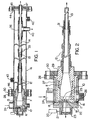
- the hydrocyclone assembly of the invention includes a generally cylindrical first portion or involute 10, a first tapered section 11 axially aligned with the involute 10, a second tapered section 12 axially aligned with section 11 and a tubular barrel 13 axially aligned with tapered section 12.
- a water collection tube 14 Connected to the end of tubular barrel 13 is a water collection tube 14.
- the involute 10 includes a body portion 15 with a closed end wall 16. An orifice 17 is located axially in the end wall 16.
- the involute section 10 also includes a plurality (preferably at least four) feed injection ports 25 which are tangentially mounted and equally spaced around the circumference thereof.
- a further feature of the present invention is a system for adjusting the effective orifice size. This is accomplished by means of a rotatable plate 18 (as shown in Figs.
- This plate 18 can be rotated either manually or by means of a power unit 20 via drive shafts 21. By this power means, any selected one of the orifices 19 in rotatable plate 18 is brought into axially alignment with orifice 17 to thereby effectively change the diameter of the orifice 17.
- the first tapered section 11 includes a body portion 29 screw connected to the body portion 15 of the involute 10. Surrounding these is an outer wall 27 through which the inlet 24 passes and to which is connected a flange plate 28.
- the body portion 29 also has a flange plate 30 which is connected to flange plate 28.
- the second tapered section 12 is screw connected to the body portion 29 of the first tapered section 11 and this in turn is connected to the water barrel or tube 13 by means of connector assembly 31.
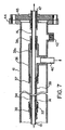
- a further assembly for separating solid particles from the water being carried down barrel 13 This includes a water collection tube 14 which is axially spaced from the end of barrel 13 by a gap 33 as best seen in Fig. 7.
- the barrel 13 and tube 14 are held in this spaced relationship by means of an outer tube 34, a T-assembly 36 and connector flanges 35, 37 and 38.
- This arrangement provides an annular chamber 39 surrounding the gap 33 and surrounding tube 13.
- This heat can be provided by means of a heating jacket formed by outer shell 41, having an inlet port 42 and an outlet port 43 for heating liquids.
- the downstream end of the outer shell 41 is connected to a flange 44, which in turn connects to a flange 45 which holds the outer end of the water collection tube 14.
- a hydrocyclone was constructed as shown in the above drawings.
- the involute 10 had a length of 4.0 cm and an interior diameter of 4.0 cm.
- the first tapered section 11 was 5.7 cm long with a large diameter of 2.0 cm.
- the second tapered section 12 had a length of 38.8 cm, with a large diameter of 2.0 cm and a small end diameter of 1.0 cm.
- the above hydrocyclone was used at a heavy oil production site to separate a well head stream (from horizontal well production) containing 20-25% by volume of oil in water.
- the hydrocyclone product stream (overflow) contained as much as 85% oil, while the oil content in the water stream (underflow) contained as little as 150 ppm oil.
- the feed flowrate varied between 35 and 50 L/min depending on pressure settings. It was found that higher feed temperatures improved separation, with a temperature of at least 40°C being preferred. In comparison, a corresponding gravity separation, such as Free Water Knockout, requires a temperature in the order of 50-75°C.
- a further test was conducted using as feed a high-water-cut production fluid containing about 2-3% by volume of oil in brine. This was separated into a clean water stream (underflow) containing no more than 100 ppm oil and an oil-rich stream (overflow) containing 5-20% oil, depending on the oil concentration of the feed.
- the feed was at a temperature of 60-65°C and the underflow discharge rate varied from 95-99% of the feed rate.
Landscapes
- Chemical & Material Sciences (AREA)
- Chemical Kinetics & Catalysis (AREA)
- Physics & Mathematics (AREA)
- Thermal Sciences (AREA)
- Fluid Mechanics (AREA)
- Cyclones (AREA)
Claims (15)
- Zyklonabscheider zum Trennen nichtmischbarer Fluida, der einen im Wesentlichen zylindrischen ersten Abschnitt (10) mit einem offenen Ende und einem geschlossenen Ende (16), einen im Wesentlichen axialen Überlaufauslass (17) in dem geschlossenen Ende (16), Einspritzöffnungen (25) in dem zylindrischen ersten Abschnitt (10), die dessen geschlossenem Ende (16) benachbart sind, mindestens einen kegelförmig zulaufenden Abschnitt (11) mit offenen Enden, der an die Strömung des offenen Endes des zylindrischen ersten Abschnitts (10) axial angeschlossen ist, und einen im Wesentlichen zylindrischen Entleerungsabschnitt (13), der an die Strömung des kegelförmigen Abschnitts (11) axial angeschlossen ist, umfasst,
dadurch gekennzeichnet, dass
mindestens vier radialsymmetrisch verteilte Einspritzöffnungen (25) geschaffen sind, die dem geschlossenen Ende (16) des zylindrischen ersten Abschnitts (10) benachbart sind, wobei die Kombination der mehreren Einspritzöffnungen (25) und die Länge des zylindrischen ersten Abschnitts (10) angepasst sind, um die Fluida innerhalb des zylindrischen ersten Abschnitts (10) vollständig in eine gerade, umgekehrte, axiale, ideale Strömung einer Phase geringerer Dichte innerhalb einer Vorwärtsströmung einer Phase höherer Dichte zu trennen. - Abscheider nach Anspruch 1, dadurch gekennzeichnet, dass die Einspritzöffnungen (25) tangential angebracht sind, um unter scherungsarmen Bedingungen einen schnell rotierenden, starken Wirbel zu schaffen.
- Abscheider nach Anspruch 2, dadurch gekennzeichnet, dass die Einspritzöffnungen (25) in gegenüberliegenden Paaren angeordnet sind.
- Abscheider nach Anspruch 1, 2 oder 3, dadurch gekennzeichnet, dass mindestens ein kegelförmig zulaufender Abschnitt einen ersten kegelförmigen Abschnitt (11) und einen zweiten kegelförmigen Abschnitt (12) aufweist.
- Abscheider nach Anspruch 1, dadurch gekennzeichnet, dass der im Wesentlichen zylindrische Entleerungsabschnitt ein Paar radial ausgerichtete Rohre (13, 14) mit einem Spalt (33) dazwischen, wobei der Spalt (33) von einem äußeren röhrenförmigen Abschnitt (34) umschlossen ist, der eine ringförmige Strömungskammer (39) schafft, und einen Entleerungsauslauf (40) umfasst, welcher mit der ringförmigen Kammer (39) verbunden ist, wodurch feste Teilchen, die in einem Flüssigkeitsstrom getragen werden, der sich durch den im Wesentlichen zylindrischen Entleerungsabschnitt bewegt, durch den Spalt (33) und Entleerungsauslauf (40) entfernt werden.
- Zyklonabscheider zum Trennen nichtmischbarer Fluida, der einen im Wesentlichen zylindrischen ersten Abschnitt (10) mit einem offenen Ende und einem geschlossenen Ende (16), einen im Wesentlichen axialen Überlaufauslass (17) in dem geschlossenen Ende (16), Einspritzöffnungen (25) in dem zylindrischen ersten Abschnitt (10), die dessen geschlossenem Ende (16) benachbart sind, mindestens einen kegelförmig zulaufenden Abschnitt (11) mit offenen Enden, der an die Strömung des offenen Endes des zylindrischen ersten Abschnitts (10) axial angeschlossen ist, und einen im Wesentlichen zylindrischen Entleerungsabschnitt (13), der an die Strömung des kegelförmigen Abschnitts (11) axial angeschlossen ist, umfasst,
dadurch gekennzeichnet, dass
mehrere radialsymmetrisch verteilte Einspritzöffnungen (25) geschaffen sind, die dem geschlossenen Ende (16) des zylindrischen ersten Abschnitts (10) benachbart sind, und ein bewegliches Glied (18) geschaffen ist, das mit dem geschlossenen Ende (16) verbunden ist und das mehrere Öffnungen (19) mit zunehmend kleinerem Durchmesser als der Überlaufauslass (17) aufweist, wobei das bewegliche Glied (18) in einer Weise beweglich ist, dass jede ausgewählte der mehreren Öffnungen (19) axial mit dem Überlaufauslass (17) ausgerichtet wird, wobei die Länge des zylindrischen ersten Abschnitts (10), die Anzahl der Einspritzöffnungen (25) und der Durchmesser der Öffnungen (19) so gewählt sind, dass Fluida innerhalb des zylindrischen ersten Abschnitts (10) in eine gerade, umgekehrte, axiale, ideale Strömung einer Phase geringerer Dichte innerhalb einer Vorwärtsströmung einer Phase höherer Dichte getrennt werden, wobei die gerade, umkehrte, axiale, ideale Strömung angepasst ist, um gleichmäßig durch eine ausgewählte Öffnung (19) hindurchzuströmen. - Abscheider nach Anspruch 6, dadurch gekennzeichnet, dass der im Wesentlichen zylindrische Entleerungsabschnitt ein Paar radial ausgerichtete Rohre (13, 14) mit einem Spalt (33) dazwischen, wobei der Spalt (33) von einem äußeren röhrenförmigen Abschnitt (34) umschlossen ist, der eine ringförmige Strömungskammer (39) schafft, und einen Entleerungsauslauf (40) umfasst, der mit der ringförmigen Kammer (39) verbunden ist, wodurch feste Teilchen, die in einem Flüssigkeitsstrom getragen werden, der sich durch den im Wesentlichen zylindrischen Entleerungsabschnitt bewegt, durch den Spalt (33) und Entleerungsauslauf (40) entfernt werden.
- Abscheider nach Anspruch 7, dadurch gekennzeichnet, dass die mehreren Öffnungen (19) in einer Platte (18) geschaffen sind, die drehbar an dem Ende des zylindrischen ersten Abschnitts (10) angebracht ist.
- Abscheider nach Anspruch 8, dadurch gekennzeichnet, dass die Platte (18) durch eine motorisch getriebene Einheit gedreht wird.
- Abscheider nach Anspruch 1 oder 6, dadurch gekennzeichnet, dass er ein äußeres Gehäuse (41) einschließt, das eine Heizkammer bildet, die den Zyklon umgibt.
- Verfahren zum Trennen einer Mischung aus nichtmischbaren Fluida unterschiedlicher Dichten, welches das Einbringen der Mischung in einen Zyklonabscheider umfasst, der einen im Wesentlichen zylindrischen ersten Abschnitt (10) mit einem offenen Ende und einem geschlossenen Ende, einen im Wesentlichen axialen Überlaufauslass (17) in dem geschlossenen Ende (16), Einspritzöffnungen (25) in dem zylindrischen ersten Abschnitt (10), die dessen geschlossenem Ende (16) benachbart sind, mindestens einen kegelförmig zulaufenden Abschnitt (11) mit offenen Enden, der an die Strömung des offenen Endes des zylindrischen ersten Abschnitts (10) axial angeschlossen ist, und einen im Wesentlichen zylindrischen Entleerungsabschnitt (13), der an die Strömung des kegelförmigen Abschnitt (11) axial angeschlossen ist, umfasst
dadurch gekennzeichnet, dass
die Mischung aus Fluida unterschiedlicher Dichten in den zylindrischen ersten Abschnitt (10) durch mindestens vier radialsymmetrisch verteilte Einspritzöffnungen (25) und längs einer ausreichenden Länge des zylindrischen ersten Abschnitts (10) eingebracht wird, wodurch die Fluida unterschiedlicher Dichten sich innerhalb des zylindrischen ersten Abschnitts (10) in eine gerade, umgekehrte, axiale, ideale Strömung einer Phase geringerer Dichte und eine Vorwärtsströmung einer Phase höherer Dichte trennen, wodurch die Phase geringerer Dichte durch den axialen Überlaufauslass (17) entfernt wird und die Phase höherer Dichte durch die zylindrische Entleerung (13) entfernt wird. - Verfahren nach Anspruch 11, dadurch gekennzeichnet, dass die Mischung nichtmischbarer Fluida eine Mischung aus Öl und Wasser ist.
- Verfahren nach Anspruch 12, dadurch gekennzeichnet, dass ein bewegliches Glied (18), das mehrere Öffnungen (19) von zunehmend kleinerem Durchmesser als der Überlaufauslass (17) aufweist, in Verbindung mit dem Überlaufauslass (17) geschaffen ist, und eine Öffnung ausgewählt wird, die dem Durchmesser der axialen idealen Strömung der Phase geringerer Dichte entspricht.
- Verfahren nach Anspruch 12, dadurch gekennzeichnet, dass die Mischung bis zu 30 % Öl enthält.
- Verfahren nach Anspruch 12, dadurch gekennzeichnet, dass die Mischung etwa 1 bis 2 % Öl enthält.
Applications Claiming Priority (3)
| Application Number | Priority Date | Filing Date | Title |
|---|---|---|---|
| US08/848,276 US5858237A (en) | 1997-04-29 | 1997-04-29 | Hydrocyclone for separating immiscible fluids and removing suspended solids |
| US848276 | 1997-04-29 | ||
| PCT/CA1998/000403 WO1998048942A1 (en) | 1997-04-29 | 1998-04-29 | Hydrocyclone for separating immiscible fluids and removing suspended solids |
Publications (2)
| Publication Number | Publication Date |
|---|---|
| EP0979148A1 EP0979148A1 (de) | 2000-02-16 |
| EP0979148B1 true EP0979148B1 (de) | 2003-10-15 |
Family
ID=25302858
Family Applications (1)
| Application Number | Title | Priority Date | Filing Date |
|---|---|---|---|
| EP98916751A Expired - Lifetime EP0979148B1 (de) | 1997-04-29 | 1998-04-29 | Hydrozyklon zur trennung von nicht mischbaren flüssigkeiten und abtrennung von suspendierten feststoffen |
Country Status (8)
| Country | Link |
|---|---|
| US (1) | US5858237A (de) |
| EP (1) | EP0979148B1 (de) |
| AU (1) | AU728425B2 (de) |
| CA (1) | CA2288239C (de) |
| DE (1) | DE69818989T2 (de) |
| DK (1) | DK0979148T3 (de) |
| NO (1) | NO316595B1 (de) |
| WO (1) | WO1998048942A1 (de) |
Families Citing this family (20)
| Publication number | Priority date | Publication date | Assignee | Title |
|---|---|---|---|---|
| USD456429S1 (en) | 1997-02-26 | 2002-04-30 | Warman International Limited | Feed housing liner for a hydrocyclone feed assembly |
| USD464067S1 (en) | 1997-02-26 | 2002-10-08 | Warman International Limited | Feed housing for a hydrocyclone feed assembly |
| AU2000247054A1 (en) * | 2000-05-02 | 2001-11-12 | Krebs International | Hydrocyclone and method for liquid-solid separation and classification |
| US7293657B1 (en) * | 2000-05-02 | 2007-11-13 | Krebs International | Hydrocyclone and method for liquid-solid separation and classification |
| US6582600B1 (en) | 2002-01-31 | 2003-06-24 | Natural Resources Canada | Two-stage hydrocyclone system |
| US6800208B2 (en) | 2003-01-10 | 2004-10-05 | United States Filter Corporation | Hydrocyclone bundle |
| GB2423490B (en) * | 2005-02-23 | 2009-05-20 | Dps | Separator |
| US7568535B2 (en) * | 2007-12-11 | 2009-08-04 | National Oilwell Varco Lp | Methods for recovery and reuse of lost circulation material |
| US8202415B2 (en) * | 2009-04-14 | 2012-06-19 | National Oilwell Varco, L.P. | Hydrocyclones for treating drilling fluid |
| US8911635B2 (en) | 2009-08-31 | 2014-12-16 | Petroleo Brasileiro S.A.—Petrobras | Hydrocyclone for the separation of fluids |
| US9896918B2 (en) | 2012-07-27 | 2018-02-20 | Mbl Water Partners, Llc | Use of ionized water in hydraulic fracturing |
| US10036217B2 (en) | 2012-07-27 | 2018-07-31 | Mbl Partners, Llc | Separation of drilling fluid |
| US9169725B1 (en) | 2013-11-10 | 2015-10-27 | John D. Jones | Method of stripping crude oil and hydraulic fracturing fluids from water using a gas sparged hydrocyclone |
| US9663385B2 (en) | 2013-11-10 | 2017-05-30 | John D Jones | Liquid purification system |
| US9150435B1 (en) | 2013-11-10 | 2015-10-06 | John D. Jones | Method of stripping volatile organic compounds from water using a gas sparged hydrocyclone |
| US20150202545A1 (en) * | 2014-01-17 | 2015-07-23 | Heartland Technology Partners Llc | Selective separation and concentration system for water soluble salts |
| US10828581B2 (en) * | 2015-01-13 | 2020-11-10 | FHNC Ltd. Co. | Wastewater separation system |
| US9827575B2 (en) | 2015-12-18 | 2017-11-28 | Metso Minerals Industries, Inc. | Controlled turbulent breakup flow |
| PT3417944T (pt) * | 2017-06-22 | 2020-07-23 | Metso Minerals Ind Inc | Separador hidrociclone |
| US11344897B1 (en) | 2019-04-05 | 2022-05-31 | Tetra Technologies, Inc. | Method and apparatus for hydrocyclone |
Family Cites Families (22)
| Publication number | Priority date | Publication date | Assignee | Title |
|---|---|---|---|---|
| FR465897A (fr) * | 1912-12-09 | 1914-04-29 | Gustav Bergen | Procédé de fabrication d'un sel alimentaire semblable au sel raffiné léger (sel fin) à partir de chlorure de sodium fondu |
| US3130157A (en) * | 1958-12-15 | 1964-04-21 | Denis F Kelsall | Hydro-cyclones |
| US3034647A (en) * | 1959-06-25 | 1962-05-15 | Ametek Inc | Cyclone separator |
| NL150350B (nl) * | 1963-10-08 | 1976-08-16 | Takeshi Horiuchi | Hydrocycloon. |
| DE1240374B (de) * | 1966-03-03 | 1967-05-11 | Westfalia Dinnendahl Groeppel | Umluftsichter |
| BE756804A (fr) * | 1969-09-29 | 1971-03-01 | Wikdahl Nils Anders Lennart | Groupement de separateur a cyclone |
| US4235363A (en) * | 1979-07-09 | 1980-11-25 | Liller Delbert I | Method of installing replacable sleeve in fixed vortex finder |
| GB2102310A (en) * | 1981-06-25 | 1983-02-02 | Nat Res Dev | Cyclone separator |
| GB2107616B (en) * | 1981-10-16 | 1986-02-05 | Nat Res Dev | Cyclone separator |
| NL8420246A (nl) * | 1983-10-06 | 1985-09-02 | Carroll Noel | Cycloonscheider. |
| DE3681768D1 (de) * | 1985-07-30 | 1991-11-07 | Hartmut Wolf | Zerstaeubungsvorrichtung. |
| CA1317237C (en) * | 1987-03-03 | 1993-05-04 | Martin Thomas Thew | Cyclone separator |
| CA1328629C (en) * | 1987-09-05 | 1994-04-19 | Peter Gregory Michaluk | Separator |
| WO1991014492A1 (en) * | 1988-09-30 | 1991-10-03 | Conoco Specialty Products, Inc. | Method and apparatus for separating liquid components from a liquid mixture |
| US4997549A (en) * | 1989-09-19 | 1991-03-05 | Advanced Processing Technologies, Inc. | Air-sparged hydrocyclone separator |
| DE3936078C2 (de) * | 1989-10-30 | 1994-02-10 | Guenter Dr Ing Slowik | Drallerzeuger für Zyklonabscheider |
| SE9100887D0 (sv) * | 1991-03-25 | 1991-03-25 | Walin Goesta Havsteknik | Saett att separera i en basvaetska foerekommande partiklar jaemte en anordning foer saettets genomfoerande |
| US5336410A (en) * | 1991-08-01 | 1994-08-09 | Conoco Specialty Products Inc. | Three chamber vessel for hydrocyclone separator |
| FR2690089B1 (fr) * | 1992-04-15 | 1994-10-21 | Elf Aquitaine | Séparateur triphasique à cyclone. |
| US5240115A (en) * | 1992-11-10 | 1993-08-31 | Beloit Technologies, Inc. | Field adjustable hydrocyclone |
| CA2142747C (en) * | 1995-02-17 | 2000-05-16 | Michael H. Kuryluk | Mineral separator |
| US5643470A (en) * | 1996-04-05 | 1997-07-01 | Amini; Bijan K. | Centrifugal flow separator method |
-
1997
- 1997-04-29 US US08/848,276 patent/US5858237A/en not_active Expired - Lifetime
-
1998
- 1998-04-29 CA CA002288239A patent/CA2288239C/en not_active Expired - Lifetime
- 1998-04-29 EP EP98916751A patent/EP0979148B1/de not_active Expired - Lifetime
- 1998-04-29 DE DE69818989T patent/DE69818989T2/de not_active Expired - Lifetime
- 1998-04-29 AU AU70245/98A patent/AU728425B2/en not_active Expired
- 1998-04-29 DK DK98916751T patent/DK0979148T3/da active
- 1998-04-29 WO PCT/CA1998/000403 patent/WO1998048942A1/en not_active Ceased
-
1999
- 1999-10-29 NO NO995304A patent/NO316595B1/no not_active IP Right Cessation
Also Published As
| Publication number | Publication date |
|---|---|
| CA2288239C (en) | 2003-12-16 |
| NO995304D0 (no) | 1999-10-29 |
| NO316595B1 (no) | 2004-03-01 |
| DE69818989D1 (de) | 2003-11-20 |
| DK0979148T3 (da) | 2004-02-23 |
| WO1998048942A1 (en) | 1998-11-05 |
| NO995304L (no) | 1999-12-29 |
| DE69818989T2 (de) | 2004-07-29 |
| US5858237A (en) | 1999-01-12 |
| AU728425B2 (en) | 2001-01-11 |
| EP0979148A1 (de) | 2000-02-16 |
| AU7024598A (en) | 1998-11-24 |
| CA2288239A1 (en) | 1998-11-05 |
Similar Documents
| Publication | Publication Date | Title |
|---|---|---|
| CA2288239C (en) | Hydrocyclone for separating immiscible fluids and removing suspended solids | |
| US3971718A (en) | Hydrocyclone separator or classifier | |
| US4722796A (en) | Cyclone separator | |
| EP2882536B1 (de) | Vorrichtung zur zyklonabscheidung eines fluids in eine gasphase und eine flüssigphase sowie behälter mit einer solchen vorrichtung | |
| US4790666A (en) | Low-shear, cyclonic mixing apparatus and method of using | |
| CA2473537C (en) | Two-stage hydrocyclone system | |
| US20020148777A1 (en) | Long free vortex cylindrical telescopic separation chamber cyclone apparatus | |
| JPH04227867A (ja) | 並流サイクロン分離器およびその適用方法 | |
| CA1197478A (en) | Cyclone separators | |
| AU2006280554A1 (en) | Hydrocyclone | |
| AU8333287A (en) | Cyclone separator | |
| CN101773878B (zh) | 旋流分离器 | |
| US5100552A (en) | Cyclone separator with enlarged underflow section | |
| NO169106B (no) | Syklonseparator. | |
| US5225082A (en) | Hydrocyclone with finely tapered tail section | |
| US5133861A (en) | Hydricyclone separator with turbulence shield | |
| US5180493A (en) | Rotating hydrocyclone separator with turbulence shield | |
| JP3773536B2 (ja) | 滞在時間の長い逆ハイドロサイクロンクリーナ | |
| RU2236888C1 (ru) | Сепаратор | |
| CA2235011C (en) | Hydrocyclone separator | |
| RU2097142C1 (ru) | Гидроциклон | |
| WO2005049175A1 (en) | Apparatus and method for separation of gases | |
| SU889049A1 (ru) | Сепаратор | |
| RU2206408C1 (ru) | Гидроциклон |
Legal Events
| Date | Code | Title | Description |
|---|---|---|---|
| PUAI | Public reference made under article 153(3) epc to a published international application that has entered the european phase |
Free format text: ORIGINAL CODE: 0009012 |
|
| 17P | Request for examination filed |
Effective date: 19991122 |
|
| AK | Designated contracting states |
Kind code of ref document: A1 Designated state(s): DE DK ES FI FR GB IE IT NL SE |
|
| GRAH | Despatch of communication of intention to grant a patent |
Free format text: ORIGINAL CODE: EPIDOS IGRA |
|
| GRAS | Grant fee paid |
Free format text: ORIGINAL CODE: EPIDOSNIGR3 |
|
| GRAA | (expected) grant |
Free format text: ORIGINAL CODE: 0009210 |
|
| AK | Designated contracting states |
Kind code of ref document: B1 Designated state(s): DE DK ES FI FR GB IE IT NL SE |
|
| PG25 | Lapsed in a contracting state [announced via postgrant information from national office to epo] |
Ref country code: IT Free format text: LAPSE BECAUSE OF FAILURE TO SUBMIT A TRANSLATION OF THE DESCRIPTION OR TO PAY THE FEE WITHIN THE PRESCRIBED TIME-LIMIT;WARNING: LAPSES OF ITALIAN PATENTS WITH EFFECTIVE DATE BEFORE 2007 MAY HAVE OCCURRED AT ANY TIME BEFORE 2007. THE CORRECT EFFECTIVE DATE MAY BE DIFFERENT FROM THE ONE RECORDED. Effective date: 20031015 Ref country code: FI Free format text: LAPSE BECAUSE OF FAILURE TO SUBMIT A TRANSLATION OF THE DESCRIPTION OR TO PAY THE FEE WITHIN THE PRESCRIBED TIME-LIMIT Effective date: 20031015 |
|
| REG | Reference to a national code |
Ref country code: GB Ref legal event code: FG4D |
|
| REG | Reference to a national code |
Ref country code: IE Ref legal event code: FG4D |
|
| REF | Corresponds to: |
Ref document number: 69818989 Country of ref document: DE Date of ref document: 20031120 Kind code of ref document: P |
|
| PG25 | Lapsed in a contracting state [announced via postgrant information from national office to epo] |
Ref country code: SE Free format text: LAPSE BECAUSE OF FAILURE TO SUBMIT A TRANSLATION OF THE DESCRIPTION OR TO PAY THE FEE WITHIN THE PRESCRIBED TIME-LIMIT Effective date: 20040115 |
|
| PG25 | Lapsed in a contracting state [announced via postgrant information from national office to epo] |
Ref country code: ES Free format text: LAPSE BECAUSE OF FAILURE TO SUBMIT A TRANSLATION OF THE DESCRIPTION OR TO PAY THE FEE WITHIN THE PRESCRIBED TIME-LIMIT Effective date: 20040126 |
|
| REG | Reference to a national code |
Ref country code: DK Ref legal event code: T3 |
|
| PG25 | Lapsed in a contracting state [announced via postgrant information from national office to epo] |
Ref country code: IE Free format text: LAPSE BECAUSE OF NON-PAYMENT OF DUE FEES Effective date: 20040429 |
|
| ET | Fr: translation filed | ||
| PLBE | No opposition filed within time limit |
Free format text: ORIGINAL CODE: 0009261 |
|
| STAA | Information on the status of an ep patent application or granted ep patent |
Free format text: STATUS: NO OPPOSITION FILED WITHIN TIME LIMIT |
|
| 26N | No opposition filed |
Effective date: 20040716 |
|
| REG | Reference to a national code |
Ref country code: IE Ref legal event code: MM4A |
|
| REG | Reference to a national code |
Ref country code: FR Ref legal event code: PLFP Year of fee payment: 19 |
|
| REG | Reference to a national code |
Ref country code: FR Ref legal event code: PLFP Year of fee payment: 20 |
|
| PGFP | Annual fee paid to national office [announced via postgrant information from national office to epo] |
Ref country code: NL Payment date: 20170428 Year of fee payment: 20 |
|
| PGFP | Annual fee paid to national office [announced via postgrant information from national office to epo] |
Ref country code: DE Payment date: 20170421 Year of fee payment: 20 Ref country code: FR Payment date: 20170420 Year of fee payment: 20 Ref country code: DK Payment date: 20170424 Year of fee payment: 20 Ref country code: GB Payment date: 20170420 Year of fee payment: 20 |
|
| REG | Reference to a national code |
Ref country code: DE Ref legal event code: R071 Ref document number: 69818989 Country of ref document: DE |
|
| REG | Reference to a national code |
Ref country code: DK Ref legal event code: EUP Effective date: 20180429 |
|
| REG | Reference to a national code |
Ref country code: NL Ref legal event code: MK Effective date: 20180428 |
|
| REG | Reference to a national code |
Ref country code: GB Ref legal event code: PE20 Expiry date: 20180428 |
|
| PG25 | Lapsed in a contracting state [announced via postgrant information from national office to epo] |
Ref country code: GB Free format text: LAPSE BECAUSE OF EXPIRATION OF PROTECTION Effective date: 20180428 |