EP0979194B1 - Engin de loisir nautique motorise - Google Patents
Engin de loisir nautique motorise Download PDFInfo
- Publication number
- EP0979194B1 EP0979194B1 EP98922902A EP98922902A EP0979194B1 EP 0979194 B1 EP0979194 B1 EP 0979194B1 EP 98922902 A EP98922902 A EP 98922902A EP 98922902 A EP98922902 A EP 98922902A EP 0979194 B1 EP0979194 B1 EP 0979194B1
- Authority
- EP
- European Patent Office
- Prior art keywords
- hull
- nozzle
- craft according
- suction box
- water
- Prior art date
- Legal status (The legal status is an assumption and is not a legal conclusion. Google has not performed a legal analysis and makes no representation as to the accuracy of the status listed.)
- Expired - Lifetime
Links
- XLYOFNOQVPJJNP-UHFFFAOYSA-N water Substances O XLYOFNOQVPJJNP-UHFFFAOYSA-N 0.000 title claims abstract description 15
- 230000005540 biological transmission Effects 0.000 claims description 4
- 230000002093 peripheral effect Effects 0.000 claims description 3
- 238000007789 sealing Methods 0.000 claims description 3
- 238000001816 cooling Methods 0.000 claims description 2
- 239000000428 dust Substances 0.000 claims description 2
- 230000003247 decreasing effect Effects 0.000 abstract description 3
- 239000003380 propellant Substances 0.000 description 8
- 239000000463 material Substances 0.000 description 3
- 235000005921 Cynara humilis Nutrition 0.000 description 1
- 240000002228 Cynara humilis Species 0.000 description 1
- 229910000831 Steel Inorganic materials 0.000 description 1
- 239000006096 absorbing agent Substances 0.000 description 1
- 230000001133 acceleration Effects 0.000 description 1
- 230000000295 complement effect Effects 0.000 description 1
- 238000010276 construction Methods 0.000 description 1
- 239000000498 cooling water Substances 0.000 description 1
- 238000013016 damping Methods 0.000 description 1
- 238000012423 maintenance Methods 0.000 description 1
- 235000013372 meat Nutrition 0.000 description 1
- 239000002991 molded plastic Substances 0.000 description 1
- 238000000465 moulding Methods 0.000 description 1
- 239000004033 plastic Substances 0.000 description 1
- 230000001681 protective effect Effects 0.000 description 1
- 230000035939 shock Effects 0.000 description 1
- 239000010959 steel Substances 0.000 description 1
- 238000011144 upstream manufacturing Methods 0.000 description 1
Images



Classifications
-
- B—PERFORMING OPERATIONS; TRANSPORTING
- B63—SHIPS OR OTHER WATERBORNE VESSELS; RELATED EQUIPMENT
- B63H—MARINE PROPULSION OR STEERING
- B63H25/00—Steering; Slowing-down otherwise than by use of propulsive elements; Dynamic anchoring, i.e. positioning vessels by means of main or auxiliary propulsive elements
- B63H25/06—Steering by rudders
- B63H25/08—Steering gear
- B63H25/10—Steering gear with mechanical transmission
-
- B—PERFORMING OPERATIONS; TRANSPORTING
- B63—SHIPS OR OTHER WATERBORNE VESSELS; RELATED EQUIPMENT
- B63B—SHIPS OR OTHER WATERBORNE VESSELS; EQUIPMENT FOR SHIPPING
- B63B1/00—Hydrodynamic or hydrostatic features of hulls or of hydrofoils
- B63B1/02—Hydrodynamic or hydrostatic features of hulls or of hydrofoils deriving lift mainly from water displacement
- B63B1/04—Hydrodynamic or hydrostatic features of hulls or of hydrofoils deriving lift mainly from water displacement with single hull
- B63B1/041—Hydrodynamic or hydrostatic features of hulls or of hydrofoils deriving lift mainly from water displacement with single hull with disk-shaped hull
-
- B—PERFORMING OPERATIONS; TRANSPORTING
- B63—SHIPS OR OTHER WATERBORNE VESSELS; RELATED EQUIPMENT
- B63B—SHIPS OR OTHER WATERBORNE VESSELS; EQUIPMENT FOR SHIPPING
- B63B34/00—Vessels specially adapted for water sports or leisure; Body-supporting devices specially adapted for water sports or leisure
- B63B34/10—Power-driven personal watercraft, e.g. water scooters; Accessories therefor
-
- B—PERFORMING OPERATIONS; TRANSPORTING
- B63—SHIPS OR OTHER WATERBORNE VESSELS; RELATED EQUIPMENT
- B63B—SHIPS OR OTHER WATERBORNE VESSELS; EQUIPMENT FOR SHIPPING
- B63B34/00—Vessels specially adapted for water sports or leisure; Body-supporting devices specially adapted for water sports or leisure
- B63B34/50—Body-supporting buoyant devices, e.g. bathing boats or water cycles
- B63B34/52—Inflatable or partly inflatable
-
- B—PERFORMING OPERATIONS; TRANSPORTING
- B63—SHIPS OR OTHER WATERBORNE VESSELS; RELATED EQUIPMENT
- B63B—SHIPS OR OTHER WATERBORNE VESSELS; EQUIPMENT FOR SHIPPING
- B63B5/00—Hulls characterised by their construction of non-metallic material
- B63B5/24—Hulls characterised by their construction of non-metallic material made predominantly of plastics
-
- B—PERFORMING OPERATIONS; TRANSPORTING
- B63—SHIPS OR OTHER WATERBORNE VESSELS; RELATED EQUIPMENT
- B63B—SHIPS OR OTHER WATERBORNE VESSELS; EQUIPMENT FOR SHIPPING
- B63B59/00—Hull protection specially adapted for vessels; Cleaning devices specially adapted for vessels
- B63B59/02—Fenders integral with waterborne vessels or specially adapted therefor, e.g. fenders forming part of the hull or incorporated in the hull; Rubbing-strakes
-
- B—PERFORMING OPERATIONS; TRANSPORTING
- B63—SHIPS OR OTHER WATERBORNE VESSELS; RELATED EQUIPMENT
- B63H—MARINE PROPULSION OR STEERING
- B63H11/00—Marine propulsion by water jets
- B63H11/02—Marine propulsion by water jets the propulsive medium being ambient water
- B63H11/04—Marine propulsion by water jets the propulsive medium being ambient water by means of pumps
- B63H11/08—Marine propulsion by water jets the propulsive medium being ambient water by means of pumps of rotary type
-
- B—PERFORMING OPERATIONS; TRANSPORTING
- B63—SHIPS OR OTHER WATERBORNE VESSELS; RELATED EQUIPMENT
- B63B—SHIPS OR OTHER WATERBORNE VESSELS; EQUIPMENT FOR SHIPPING
- B63B59/00—Hull protection specially adapted for vessels; Cleaning devices specially adapted for vessels
- B63B59/02—Fenders integral with waterborne vessels or specially adapted therefor, e.g. fenders forming part of the hull or incorporated in the hull; Rubbing-strakes
- B63B2059/025—Fenders integral with waterborne vessels or specially adapted therefor, e.g. fenders forming part of the hull or incorporated in the hull; Rubbing-strakes pneumatic, e.g. inflatable
-
- Y—GENERAL TAGGING OF NEW TECHNOLOGICAL DEVELOPMENTS; GENERAL TAGGING OF CROSS-SECTIONAL TECHNOLOGIES SPANNING OVER SEVERAL SECTIONS OF THE IPC; TECHNICAL SUBJECTS COVERED BY FORMER USPC CROSS-REFERENCE ART COLLECTIONS [XRACs] AND DIGESTS
- Y10—TECHNICAL SUBJECTS COVERED BY FORMER USPC
- Y10T—TECHNICAL SUBJECTS COVERED BY FORMER US CLASSIFICATION
- Y10T74/00—Machine element or mechanism
- Y10T74/20—Control lever and linkage systems
Definitions
- the present invention relates to a motorized nautical leisure.
- the devices known in the state of the art are adapted to sports, by users savvy accepting user costs relatively high.
- the object of the present invention is to remedy to these different disadvantages, and to reconcile different constraints, by offering a recreational vehicle nautical consisting of a hull fitted with a propellant according to claim 1.
- the propellant is a hydrojet type propellant associated with a water suction propeller placed in a suction box opening into the bottom of the shell, the outlet of the suction box opening into a nozzle, the suction box comprising an intake element composed of an inner tubular part and a base having a fixing disc on the bottom of the chassis extended by a tubular part, the connection between the inner tubular part on which the nozzle, and the external part is effected by a seal elastic ensuring the fixing and limiting functions vibration transmission and sealing.
- the shell has a rim device for receiving an inflatable envelope annular.
- the envelope inflatable has an annular shape having at its rear part a cutout for the passage of a segment rigid including the directional nozzle.
- the rigid segment is extended by a mast supporting a sun visor.
- the propellant consists of a low power motor associated with a water suction propeller placed in a box suction opening into the bottom of the shell, the outlet of the suction box opening into a nozzle having a decreasing section and a wall helical.
- the propeller has three pale in the form of helical ramps extending a hub substantially cylindrical.
- the nozzle has a water intake in the area of high cross-section engine cooling.
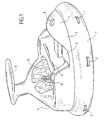
- FIG. 1 shows a front view of the machine according to an exemplary embodiment of the invention.
- This machine consists of a pressed sheet steel chassis or of molded plastic material having a rim peripheral on which a reserve of annular buoyancy (1).
- This buoyancy reserve inflatable is divided into several compartments for security issues. It has strips of handling (2) facilitating the porting of the machine.
- the chassis is surmounted by a rigid plastic shell (3) molded. It has a hemispherical front part (4) fitted with a hatch (8) for filling the tank petrol. The middle part is lowered and forms the footrest. It also presents a part (6) raised forming the seats.
- the rear part (9) forms a trunk divided into an upper compartment to receive user's accessories or bags, and a compartment lower containing the propellant.
- the object is overcome by a sun visor (11). It also has a controller (12) to control the direction and operation of the propellant.
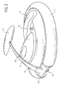
- FIG. 2 shows a rear view of the craft.
- the rear part (9) of the shell has a hatch (12) allowing access to a storage chest.
- the sun visor (11) is supported by a mast (13) held by a rigid base (14) fixed to the chassis.
- the ends of the tank buoyancy (1) are also attached to this base rigid (14).
- This base has a cutout for the directional nozzle (15).
- FIG 3 shows a detailed view of the buoyancy reserve. It is made up of an element inflatable of generally annular shape, of which the rear part has a cutout (16) of complementary shape to the base rigid (14) which fits in this cut. Both front faces (17, 18) are fixed on the base (14) by bolts or any equivalent means.
- Carrying straps (2) are attached to the edge of the buoyancy reserve. Valves (20) allow the inflation of the different compartments.
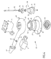
- Figure 4 shows an exploded view of the group propellant.
- the intake element (22) is formed by a cylindrical part mounted on the bottom of the chassis by Silentbloc or damping means capable of reducing noise and vibration transmission.
- the intake element is composed of a part inner tubular (24) and a base (25) has a disc (26) for fixing to the bottom of the chassis extended by a tubular part (27).
- the link between the party inner tubular (24) on which the nozzle (21), and the outer part (25) is effected by a elastic seal (28) ensuring the functions of fixing, limitation of vibration transmission and sealing.
- the intake element (22) opens on the bottom of the chassis, in a substantially perpendicular direction at the bottom, through a protective grid (23).
- the other end of the intake element (22) has a collar (29) for fixing to the nozzle (21).
- a propeller (30) Inside the intake element (22) is placed a propeller (30) whose shape evokes that of a meat grinder. It presents three helical blades (31 to 33) welded to a hub (34) of cylindrical shape and preferably conical diverging upstream.
- a connecting axis (35) provides the link with the heat engine. This axis of connection passes through a guide (37) fixed on the nozzle, and is held by bearings (36).
- the nozzle has a front entrance, facing down, and an exit radial, oriented rearward, perpendicular to the admission direction. It has an interior section decreasing, and a helical wall causing a acceleration of the water jet.
- Another socket (41) arranged on the ejection pipe (42) ensures the suction function of the water possibly stagnating at chassis bottom.
- a directional nozzle (43) articulated on the end of the ejection tube (42) ensures the orientation of the jet in the horizontal plane.
- This nozzle directional (43) is controlled by the handle (12). The connection is ensured by a single cable.
- FIG. 5 represents a detailed view of the control lever.
- the handle consists of a rod (50) provided at its end with a trackball (51).
- the rod (50) is articulated around two axes perpendicular.
- the first axis is defined by a cup hemispherical (52) movable relative to a base hemispherical (53)
- This base has a chute annular (55) for collecting drops of water and dust.
- This chute opens onto the outside surface of the hull by a discharge slot.
- the base is extended by a fixing plate (56) for mounting on the hull having for this purpose a circular hole.
- the second axis is constituted by a pivot (58).
- the end (60) of a cable is fixed to the part lower (61) of the rod.
- the cable has a sheath stopped by a stop (59). This cable is connected to the arm of engine accelerator control.
- the rod In the perpendicular direction, the rod has a second anchor point (62) of a means of directional nozzle control.
- Figure 6 shows a sectional view of a variant of the hull.
- the shell is produced under form of a rigid structure, for example by molding a material such as P.V.C.
- This shell has an external box annular (100) on which is glued a crown (101) dimpled forming a shock absorber.
- This crown presents a section in the shape of an arc of a circle, and presents longitudinal channels giving it elasticity.
- This crown (101) is produced by extruding such material that of P.V.C.
Landscapes
- Ocean & Marine Engineering (AREA)
- Chemical & Material Sciences (AREA)
- Engineering & Computer Science (AREA)
- Combustion & Propulsion (AREA)
- Mechanical Engineering (AREA)
- Physics & Mathematics (AREA)
- Fluid Mechanics (AREA)
- Toys (AREA)
- Cleaning Or Clearing Of The Surface Of Open Water (AREA)
- Jet Pumps And Other Pumps (AREA)
- Structures Of Non-Positive Displacement Pumps (AREA)
- Magnetic Bearings And Hydrostatic Bearings (AREA)
- Superconductors And Manufacturing Methods Therefor (AREA)
- Automatic Cycles, And Cycles In General (AREA)
- Nozzles (AREA)
Description
- la figure 1 représente une vue de face de l'engin selon l'invention ;
- la figure 2 représente une vue arrière de l'engin ;
- la figure 3 représente une vue en perspective de l'enveloppe gonflable ;
- la figure 4 représente une vue éclatée du propulseur ;
- la figure 5 représente une vue en détail de la manette de commande ;
- la figure 6 représente une vue en coupe d'une variante de réalisation de la coque.
Claims (10)
- Engin de loisir nautique constitué par une coque rigide munie d'un propulseur caractérisé en ce que le propulseur est un propulseur de type hydrojet associé à une hélice d'aspiration d'eau placée dans une boíte d'aspiration débouchant dans le fond de la coque, la sortie de la boíte d'aspiration débouchant dans une tuyère, la boíte d'aspiration comportant un élément d'admission (22) composé d'une partie tubulaire intérieure (24) et d'une embase (25) présentant un disque (26) de fixation sur le fond du châssis prolongée par une partie tubulaire (27), la liaison entre la partie tubulaire intérieure (24) sur laquelle est solidarisée la tuyère (21), et la partie extérieure (25) s'effectuant par un joint élastique (28) assurant les fonction de fixation, de limitation de la transmission des vibrations et d'étanchéité.
- Engin de loisir nautique selon la revendication 1, caractérisé en ce que la coque présente une jante périphérique pour recevoir une enveloppe de forme annulaire.
- Engin de loisir nautique selon la revendication 1 ou 2 caractérisé en ce que l'enveloppe gonflable présente une forme annulaire présentant à sa partie arrière une découpe pour le passage d'un segment rigide comprenant la tuyère directionnelle.
- Engin de loisir nautique selon la revendication 1 caractérisé en ce que le segment rigide est prolongé par un mât supportant un pare-soleil.
- Engin de loisir nautique selon l'une quelconque des revendications précédentes caractérisé en ce que le propulseur est constitué par un moteur de faible puissance associé à une hélice d'aspiration d'eau placée dans une boíte d'aspiration débouchant dans le fond de la coque, la sortie de la boíte d'aspiration débouchant dans une tuyère présentant une section décroissante et une paroi hélicoïdale.
- Engin de loisir nautique selon la revendication 5 caractérisé en ce que l'hélice présente trois pâles en forme de rampes hélicoïdales prolongeant un moyeu sensiblement cylindrique.
- Engin de loisir nautique selon la revendication 6 caractérisé en ce que la tuyère présente dans la zone de forte section une prise d'eau pour le refroidissement du moteur.
- Engin de loisir nautique selon l'une quelconque des revendications précédentes caractérisé en ce que la coque présente une jante périphérique pour recevoir une enveloppe gonflable, et en ce que le propulseur est un propulseur de type hydrojet constitué par un moteur de faible puissance associé à une hélice d'aspiration d'eau placée dans une boíte d'aspiration débouchant dans le fond de la coque, la sortie de la boíte d'aspiration débouchant dans une tuyère.
- Engin de loisir nautique selon l'une quelconque des revendications précédentes caractérisé en ce que la manette de commande (12) est articulée sur une coupelle hémisphérique (52) mobile par rapport à une embase hémisphérique (53).
- Engin de loisir nautique selon la revendication 9 caractérisé en ce que cette embase (53) présente une goulotte annulaire (55) pour le recueil des gouttes d'eau et des poussières.
Applications Claiming Priority (3)
| Application Number | Priority Date | Filing Date | Title |
|---|---|---|---|
| FR9705421A FR2762823B1 (fr) | 1997-04-30 | 1997-04-30 | Engin de loisir nautique motorise |
| FR9705421 | 1997-04-30 | ||
| PCT/FR1998/000869 WO1998049047A2 (fr) | 1997-04-30 | 1998-04-29 | Engin de loisir nautique motorise |
Publications (2)
| Publication Number | Publication Date |
|---|---|
| EP0979194A2 EP0979194A2 (fr) | 2000-02-16 |
| EP0979194B1 true EP0979194B1 (fr) | 2002-02-06 |
Family
ID=9506516
Family Applications (1)
| Application Number | Title | Priority Date | Filing Date |
|---|---|---|---|
| EP98922902A Expired - Lifetime EP0979194B1 (fr) | 1997-04-30 | 1998-04-29 | Engin de loisir nautique motorise |
Country Status (7)
| Country | Link |
|---|---|
| US (1) | US6375522B1 (fr) |
| EP (1) | EP0979194B1 (fr) |
| AT (1) | ATE212926T1 (fr) |
| DE (1) | DE69803759D1 (fr) |
| ES (1) | ES2172892T3 (fr) |
| FR (1) | FR2762823B1 (fr) |
| WO (1) | WO1998049047A2 (fr) |
Families Citing this family (9)
| Publication number | Priority date | Publication date | Assignee | Title |
|---|---|---|---|---|
| FR2808253A1 (fr) * | 2000-04-26 | 2001-11-02 | Jean Francois Vincent | Saillie securitaire nautique |
| US6584926B1 (en) * | 2002-03-01 | 2003-07-01 | G. G. Schmitt & Sons, Inc. | T-top apparatus with built-in seat for boats |
| EP1470998A1 (fr) * | 2003-04-25 | 2004-10-27 | Dennis Thomas Copestake | Bateau en forme de disque |
| US6773319B1 (en) * | 2003-08-11 | 2004-08-10 | Archie M. Carlini, Jr. | Water jet powered floating device for pools |
| US7731553B2 (en) * | 2007-10-09 | 2010-06-08 | Surfango, Inc. | Watercraft propelled by a water jet |
| US20120295501A1 (en) | 2010-11-05 | 2012-11-22 | Kennon Guglielmo | Apparatus and Method for the Control of Engine Throttle for Inboard and Outboard Boat Motors |
| US8888544B1 (en) | 2011-12-01 | 2014-11-18 | Enovation Controls, Llc | Versatile control handle for watercraft docking system |
| US8789487B2 (en) * | 2012-07-20 | 2014-07-29 | Jeffrey D. Lizzio | Personal watercraft |
| CN103010420A (zh) * | 2012-12-10 | 2013-04-03 | 苏州益童游乐设备有限公司 | 一种新型儿童碰碰船 |
Family Cites Families (41)
| Publication number | Priority date | Publication date | Assignee | Title |
|---|---|---|---|---|
| US3146587A (en) * | 1962-04-09 | 1964-09-01 | Then Sophia | Water-jet propulsion means for boats |
| US3391669A (en) * | 1966-11-04 | 1968-07-09 | William R. Buster | Circular boat |
| IT987301B (it) * | 1973-01-25 | 1975-02-20 | Generali Vittorio | Pompa a idrogetto per piccole imbarcazioni |
| FR2261175A1 (en) * | 1974-02-15 | 1975-09-12 | Borras Andre | Water jet propulsion unit for inflatable craft - casing secured by bolts to rear of hull, sleeves slide over buoyancy tubes |
| US4044704A (en) * | 1976-06-28 | 1977-08-30 | Miller Gerald R | Saucer boat |
| FR2375085A1 (fr) * | 1976-12-23 | 1978-07-21 | Sillinger Tibor | Bateau pneumatique perfectionne |
| US4459117A (en) * | 1977-04-25 | 1984-07-10 | Jordan Robert L | Liquid jet propulsion |
| US4239013A (en) * | 1977-10-21 | 1980-12-16 | Haynes Hendrick W | Propelling means |
| US4138963A (en) * | 1977-10-26 | 1979-02-13 | Thompson William C | Boat steering mechanism |
| US4375631A (en) * | 1981-04-09 | 1983-03-01 | Ampex Corporation | Joystick control |
| US4437841A (en) * | 1981-11-04 | 1984-03-20 | Stallman Richard C | Outboard jet drive steering mechanism |
| US4520746A (en) * | 1982-01-05 | 1985-06-04 | Walters William F | Flotation collar |
| FR2555541A1 (fr) * | 1983-11-29 | 1985-05-31 | Grimaud Const Meca | Plage flottante |
| US4587917A (en) * | 1984-06-11 | 1986-05-13 | Cantin Donald W | Multi-use watercraft |
| JPS61229690A (ja) * | 1985-04-03 | 1986-10-13 | Kawasaki Heavy Ind Ltd | 小型滑走艇のハンドル支持装置 |
| GB8524232D0 (en) * | 1985-10-02 | 1985-11-06 | Barrus Ltd E P | I c engine air intake |
| US4792282A (en) * | 1987-06-03 | 1988-12-20 | A. Janet Jordan | Liquid pump |
| US4925408A (en) * | 1987-09-14 | 1990-05-15 | Koronis Parts, Inc. | Intake and pump assembly for aquatic vehicle |
| FR2621293B1 (fr) * | 1987-10-05 | 1992-03-20 | Achdjean Patricia | Dispositif d'embarcation pour la promenade et la relaxation |
| FR2636296A1 (fr) * | 1988-09-15 | 1990-03-16 | Giraudet Bernard | Vehicule flottant pour une ou plusieurs personnes |
| FR2637558A1 (fr) | 1988-10-06 | 1990-04-13 | Martin Jean Yves | Engin motonautique tractant le ou les utilisateurs au planing sur l'eau |
| US4964821A (en) * | 1989-05-30 | 1990-10-23 | Autoboat Corporation | Jet powered rigid inflatable boat with dead-man switch |
| US4942838A (en) * | 1989-06-23 | 1990-07-24 | Yamaha Hatsudoki Kabushiki Kaisha | Inflatable watercraft with portable engine package |
| DE4017144A1 (de) * | 1990-05-28 | 1991-12-05 | Kusan Kristian | Durch wasserstrahlantrieb angetriebenes schlauchboot mit starrem rumpf |
| US5081947A (en) * | 1990-06-15 | 1992-01-21 | Holden Wesley G | Boat assembly |
| FR2664205B1 (fr) * | 1990-07-06 | 1992-10-23 | Zodiac Int | Embarcation a coque mixte avec carene rigide et boudin gonflable de flottabilite. |
| US4994669A (en) * | 1990-07-29 | 1991-02-19 | Stern Michael A | Opto-electrical joystick switch having a resilient, rigidly mounted central shaft |
| JPH04345591A (ja) * | 1991-05-24 | 1992-12-01 | Sanshin Ind Co Ltd | ジェット推進艇 |
| JP2559942B2 (ja) * | 1992-03-19 | 1996-12-04 | 川崎重工業株式会社 | 水ジェット推進式小型滑走艇のポンプ取付構造 |
| US5184564A (en) * | 1992-03-25 | 1993-02-09 | Team Scarab, Inc. | Boat for personal watercraft |
| JPH05286489A (ja) * | 1992-04-14 | 1993-11-02 | Sanshin Ind Co Ltd | ウォータージェット推進機 |
| US5289793A (en) * | 1992-04-17 | 1994-03-01 | Omnithruster Inc. | Heliconic thruster system for a marine vessel |
| US5282437A (en) * | 1992-08-21 | 1994-02-01 | Avillez De Basto Luiz J | Personal marine transport |
| USD355252S (en) * | 1992-09-08 | 1995-02-07 | Andersen Paul H | Helicoidal impeller for use in jet propelled watercraft |
| US5362269A (en) * | 1992-10-29 | 1994-11-08 | Leach Peter M | Personal water vehicle |
| US5331914A (en) * | 1992-11-25 | 1994-07-26 | Salmons Larry W | Highly stable one-man boat |
| US5490474A (en) * | 1993-04-27 | 1996-02-13 | Yamaha Hatsudoki Kabushiki Kaisha | Watercraft |
| US5491462A (en) * | 1994-02-22 | 1996-02-13 | Wico Corporation | Joystick controller |
| JP3014604B2 (ja) * | 1994-11-18 | 2000-02-28 | 株式会社東海理化電機製作所 | スイッチ |
| FR2728863A1 (fr) | 1994-12-30 | 1996-07-05 | Bourgault Yves Marie Roger | Planche a moteur |
| US5744765A (en) * | 1995-06-19 | 1998-04-28 | Sumitomo Wiring Systems, Ltd. | Lever switch with support walls for supporting movable contact points and method of detecting an operating direction of a lever switch |
-
1997
- 1997-04-30 FR FR9705421A patent/FR2762823B1/fr not_active Expired - Fee Related
-
1998
- 1998-04-29 AT AT98922902T patent/ATE212926T1/de not_active IP Right Cessation
- 1998-04-29 EP EP98922902A patent/EP0979194B1/fr not_active Expired - Lifetime
- 1998-04-29 DE DE69803759T patent/DE69803759D1/de not_active Expired - Lifetime
- 1998-04-29 ES ES98922902T patent/ES2172892T3/es not_active Expired - Lifetime
- 1998-04-29 WO PCT/FR1998/000869 patent/WO1998049047A2/fr not_active Ceased
-
1999
- 1999-10-22 US US09/442,732 patent/US6375522B1/en not_active Expired - Fee Related
Also Published As
| Publication number | Publication date |
|---|---|
| US6375522B1 (en) | 2002-04-23 |
| ATE212926T1 (de) | 2002-02-15 |
| ES2172892T3 (es) | 2002-10-01 |
| FR2762823A1 (fr) | 1998-11-06 |
| FR2762823B1 (fr) | 1999-07-30 |
| DE69803759D1 (de) | 2002-03-21 |
| EP0979194A2 (fr) | 2000-02-16 |
| WO1998049047A2 (fr) | 1998-11-05 |
| WO1998049047A3 (fr) | 1999-02-11 |
Similar Documents
| Publication | Publication Date | Title |
|---|---|---|
| EP0979194B1 (fr) | Engin de loisir nautique motorise | |
| FR2920406A3 (fr) | Appareil de propulsion actionne manuellement | |
| EP4183955A1 (fr) | Aspirateur autonome à hélice pour le nettoyage de piscines | |
| FR2728863A1 (fr) | Planche a moteur | |
| FR2861568A1 (fr) | Boitier d'appareil electromenager de preparation culinaire prevu pour etre tenu a la main selon differentes positions | |
| EP4294716A1 (fr) | Systeme generateur de portance et bateau muni d'un tel systeme | |
| FR2524940A1 (fr) | Outil hydraulique sous-marin | |
| FR3103780A1 (fr) | Engin nautique gonflable à motorisation électrique destiné à être piloté en position debout | |
| FR2796036A1 (fr) | Bateau a propulsion electrique | |
| FR2497488A3 (fr) | Embarcation pour conduite d'une seule main | |
| EP3030480B1 (fr) | Embarcation pneumatque a carene en v et volets | |
| FR3120349A1 (fr) | Embarcation motorisée à propulsion électrique subaquatique | |
| EP4155188B1 (fr) | Système flottant comprenant une planche gonflable flottante et un système de déplacement | |
| FR2555958A1 (fr) | Engin nautique a moteur de faible puissance | |
| FR2625684A1 (fr) | Engin propulseur pour nageur | |
| FR2756251A1 (fr) | Embarcation gonflable a coque mixte | |
| FR2618405A1 (fr) | Propulseur aquatique individuel | |
| FR2495004A1 (fr) | Jouet d'eau et son procede d'utilisation | |
| WO2019202254A2 (fr) | Embarcation gonflable comportant un organe de flottaison, une unité de direction et une unité de propulsion | |
| WO2009101373A2 (fr) | Vehicule nautique compact et de poids leger | |
| FR3023535A1 (fr) | Scooter nautique propulse par un moteur pneumatique | |
| FR2687362A1 (fr) | Bateau notamment motorise. | |
| FR2820466A1 (fr) | Dispositif de recuperation d'energie fluidique | |
| FR2708528A1 (fr) | Véhicule amphibie. | |
| FR2744640A1 (fr) | Dispositif d'aide a la nage |
Legal Events
| Date | Code | Title | Description |
|---|---|---|---|
| PUAI | Public reference made under article 153(3) epc to a published international application that has entered the european phase |
Free format text: ORIGINAL CODE: 0009012 |
|
| 17P | Request for examination filed |
Effective date: 19991026 |
|
| AK | Designated contracting states |
Kind code of ref document: A2 Designated state(s): AT BE CH CY DE DK ES FI FR GB GR IE IT LI LU MC NL PT SE |
|
| 17Q | First examination report despatched |
Effective date: 20000629 |
|
| GRAG | Despatch of communication of intention to grant |
Free format text: ORIGINAL CODE: EPIDOS AGRA |
|
| GRAG | Despatch of communication of intention to grant |
Free format text: ORIGINAL CODE: EPIDOS AGRA |
|
| GRAH | Despatch of communication of intention to grant a patent |
Free format text: ORIGINAL CODE: EPIDOS IGRA |
|
| GRAH | Despatch of communication of intention to grant a patent |
Free format text: ORIGINAL CODE: EPIDOS IGRA |
|
| GRAA | (expected) grant |
Free format text: ORIGINAL CODE: 0009210 |
|
| REG | Reference to a national code |
Ref country code: GB Ref legal event code: IF02 |
|
| RIN1 | Information on inventor provided before grant (corrected) |
Inventor name: MAUVIGNER, FRANCK Inventor name: BELLENS, MARCEL |
|
| RAP1 | Party data changed (applicant data changed or rights of an application transferred) |
Owner name: OXOON S.A.R.L. |
|
| AK | Designated contracting states |
Kind code of ref document: B1 Designated state(s): AT BE CH CY DE DK ES FI FR GB GR IE IT LI LU MC NL PT SE |
|
| PG25 | Lapsed in a contracting state [announced via postgrant information from national office to epo] |
Ref country code: NL Free format text: LAPSE BECAUSE OF FAILURE TO SUBMIT A TRANSLATION OF THE DESCRIPTION OR TO PAY THE FEE WITHIN THE PRESCRIBED TIME-LIMIT Effective date: 20020206 Ref country code: IE Free format text: LAPSE BECAUSE OF FAILURE TO SUBMIT A TRANSLATION OF THE DESCRIPTION OR TO PAY THE FEE WITHIN THE PRESCRIBED TIME-LIMIT Effective date: 20020206 Ref country code: GB Free format text: LAPSE BECAUSE OF FAILURE TO SUBMIT A TRANSLATION OF THE DESCRIPTION OR TO PAY THE FEE WITHIN THE PRESCRIBED TIME-LIMIT Effective date: 20020206 Ref country code: FI Free format text: LAPSE BECAUSE OF FAILURE TO SUBMIT A TRANSLATION OF THE DESCRIPTION OR TO PAY THE FEE WITHIN THE PRESCRIBED TIME-LIMIT Effective date: 20020206 Ref country code: AT Free format text: LAPSE BECAUSE OF FAILURE TO SUBMIT A TRANSLATION OF THE DESCRIPTION OR TO PAY THE FEE WITHIN THE PRESCRIBED TIME-LIMIT Effective date: 20020206 |
|
| REF | Corresponds to: |
Ref document number: 212926 Country of ref document: AT Date of ref document: 20020215 Kind code of ref document: T |
|
| REG | Reference to a national code |
Ref country code: CH Ref legal event code: EP |
|
| REF | Corresponds to: |
Ref document number: 69803759 Country of ref document: DE Date of ref document: 20020321 |
|
| PG25 | Lapsed in a contracting state [announced via postgrant information from national office to epo] |
Ref country code: CY Free format text: LAPSE BECAUSE OF FAILURE TO SUBMIT A TRANSLATION OF THE DESCRIPTION OR TO PAY THE FEE WITHIN THE PRESCRIBED TIME-LIMIT Effective date: 20020430 |
|
| PG25 | Lapsed in a contracting state [announced via postgrant information from national office to epo] |
Ref country code: SE Free format text: LAPSE BECAUSE OF FAILURE TO SUBMIT A TRANSLATION OF THE DESCRIPTION OR TO PAY THE FEE WITHIN THE PRESCRIBED TIME-LIMIT Effective date: 20020506 Ref country code: PT Free format text: LAPSE BECAUSE OF FAILURE TO SUBMIT A TRANSLATION OF THE DESCRIPTION OR TO PAY THE FEE WITHIN THE PRESCRIBED TIME-LIMIT Effective date: 20020506 Ref country code: DK Free format text: LAPSE BECAUSE OF FAILURE TO SUBMIT A TRANSLATION OF THE DESCRIPTION OR TO PAY THE FEE WITHIN THE PRESCRIBED TIME-LIMIT Effective date: 20020506 |
|
| PG25 | Lapsed in a contracting state [announced via postgrant information from national office to epo] |
Ref country code: DE Free format text: LAPSE BECAUSE OF FAILURE TO SUBMIT A TRANSLATION OF THE DESCRIPTION OR TO PAY THE FEE WITHIN THE PRESCRIBED TIME-LIMIT Effective date: 20020507 |
|
| PGFP | Annual fee paid to national office [announced via postgrant information from national office to epo] |
Ref country code: MC Payment date: 20020510 Year of fee payment: 5 |
|
| REG | Reference to a national code |
Ref country code: CH Ref legal event code: NV Representative=s name: ABREMA AGENCE BREVETS ET MARQUES GANGUILLET & HUMP |
|
| NLV1 | Nl: lapsed or annulled due to failure to fulfill the requirements of art. 29p and 29m of the patents act | ||
| PGFP | Annual fee paid to national office [announced via postgrant information from national office to epo] |
Ref country code: LU Payment date: 20020719 Year of fee payment: 5 |
|
| GBV | Gb: ep patent (uk) treated as always having been void in accordance with gb section 77(7)/1977 [no translation filed] |
Effective date: 20020206 |
|
| REG | Reference to a national code |
Ref country code: GR Ref legal event code: EP Ref document number: 20020401593 Country of ref document: GR |
|
| REG | Reference to a national code |
Ref country code: ES Ref legal event code: FG2A Ref document number: 2172892 Country of ref document: ES Kind code of ref document: T3 |
|
| REG | Reference to a national code |
Ref country code: IE Ref legal event code: FD4D |
|
| PLBE | No opposition filed within time limit |
Free format text: ORIGINAL CODE: 0009261 |
|
| STAA | Information on the status of an ep patent application or granted ep patent |
Free format text: STATUS: NO OPPOSITION FILED WITHIN TIME LIMIT |
|
| 26N | No opposition filed |
Effective date: 20021107 |
|
| PG25 | Lapsed in a contracting state [announced via postgrant information from national office to epo] |
Ref country code: LU Free format text: LAPSE BECAUSE OF NON-PAYMENT OF DUE FEES Effective date: 20030429 |
|
| PG25 | Lapsed in a contracting state [announced via postgrant information from national office to epo] |
Ref country code: MC Free format text: LAPSE BECAUSE OF NON-PAYMENT OF DUE FEES Effective date: 20030430 |
|
| PGFP | Annual fee paid to national office [announced via postgrant information from national office to epo] |
Ref country code: BE Payment date: 20040504 Year of fee payment: 7 |
|
| PGFP | Annual fee paid to national office [announced via postgrant information from national office to epo] |
Ref country code: CH Payment date: 20040527 Year of fee payment: 7 |
|
| PG25 | Lapsed in a contracting state [announced via postgrant information from national office to epo] |
Ref country code: LI Free format text: LAPSE BECAUSE OF NON-PAYMENT OF DUE FEES Effective date: 20050430 Ref country code: CH Free format text: LAPSE BECAUSE OF NON-PAYMENT OF DUE FEES Effective date: 20050430 Ref country code: BE Free format text: LAPSE BECAUSE OF NON-PAYMENT OF DUE FEES Effective date: 20050430 |
|
| BERE | Be: lapsed |
Owner name: *OXOON S.A.R.L. Effective date: 20050430 |
|
| REG | Reference to a national code |
Ref country code: CH Ref legal event code: PL |
|
| PGFP | Annual fee paid to national office [announced via postgrant information from national office to epo] |
Ref country code: GR Payment date: 20060323 Year of fee payment: 9 |
|
| PGFP | Annual fee paid to national office [announced via postgrant information from national office to epo] |
Ref country code: ES Payment date: 20060428 Year of fee payment: 9 |
|
| PGFP | Annual fee paid to national office [announced via postgrant information from national office to epo] |
Ref country code: IT Payment date: 20060430 Year of fee payment: 9 |
|
| BERE | Be: lapsed |
Owner name: *OXOON S.A.R.L. Effective date: 20050430 |
|
| REG | Reference to a national code |
Ref country code: ES Ref legal event code: FD2A Effective date: 20070430 |
|
| PGFP | Annual fee paid to national office [announced via postgrant information from national office to epo] |
Ref country code: FR Payment date: 20080207 Year of fee payment: 11 |
|
| PG25 | Lapsed in a contracting state [announced via postgrant information from national office to epo] |
Ref country code: GR Free format text: LAPSE BECAUSE OF NON-PAYMENT OF DUE FEES Effective date: 20071102 Ref country code: ES Free format text: LAPSE BECAUSE OF NON-PAYMENT OF DUE FEES Effective date: 20070430 |
|
| PG25 | Lapsed in a contracting state [announced via postgrant information from national office to epo] |
Ref country code: IT Free format text: LAPSE BECAUSE OF NON-PAYMENT OF DUE FEES Effective date: 20070429 |
|
| REG | Reference to a national code |
Ref country code: FR Ref legal event code: ST Effective date: 20091231 |
|
| PG25 | Lapsed in a contracting state [announced via postgrant information from national office to epo] |
Ref country code: FR Free format text: LAPSE BECAUSE OF NON-PAYMENT OF DUE FEES Effective date: 20091222 |