EP0979344B1 - Piece rapportee tranchante destinee a une fraise de meulage d'un puits de forage - Google Patents
Piece rapportee tranchante destinee a une fraise de meulage d'un puits de forage Download PDFInfo
- Publication number
- EP0979344B1 EP0979344B1 EP98919299A EP98919299A EP0979344B1 EP 0979344 B1 EP0979344 B1 EP 0979344B1 EP 98919299 A EP98919299 A EP 98919299A EP 98919299 A EP98919299 A EP 98919299A EP 0979344 B1 EP0979344 B1 EP 0979344B1
- Authority
- EP
- European Patent Office
- Prior art keywords
- cutting insert
- cutting
- insert
- tab
- inserts
- Prior art date
- Legal status (The legal status is an assumption and is not a legal conclusion. Google has not performed a legal analysis and makes no representation as to the accuracy of the status listed.)
- Expired - Lifetime
Links
Images



Classifications
-
- E—FIXED CONSTRUCTIONS
- E21—EARTH OR ROCK DRILLING; MINING
- E21B—EARTH OR ROCK DRILLING; OBTAINING OIL, GAS, WATER, SOLUBLE OR MELTABLE MATERIALS OR A SLURRY OF MINERALS FROM WELLS
- E21B29/00—Cutting or destroying pipes, packers, plugs or wire lines, located in boreholes or wells, e.g. cutting of damaged pipes, of windows; Deforming of pipes in boreholes or wells; Reconditioning of well casings while in the ground
- E21B29/002—Cutting, e.g. milling, a pipe with a cutter rotating along the circumference of the pipe
-
- E—FIXED CONSTRUCTIONS
- E21—EARTH OR ROCK DRILLING; MINING
- E21B—EARTH OR ROCK DRILLING; OBTAINING OIL, GAS, WATER, SOLUBLE OR MELTABLE MATERIALS OR A SLURRY OF MINERALS FROM WELLS
- E21B29/00—Cutting or destroying pipes, packers, plugs or wire lines, located in boreholes or wells, e.g. cutting of damaged pipes, of windows; Deforming of pipes in boreholes or wells; Reconditioning of well casings while in the ground
-
- Y—GENERAL TAGGING OF NEW TECHNOLOGICAL DEVELOPMENTS; GENERAL TAGGING OF CROSS-SECTIONAL TECHNOLOGIES SPANNING OVER SEVERAL SECTIONS OF THE IPC; TECHNICAL SUBJECTS COVERED BY FORMER USPC CROSS-REFERENCE ART COLLECTIONS [XRACs] AND DIGESTS
- Y10—TECHNICAL SUBJECTS COVERED BY FORMER USPC
- Y10T—TECHNICAL SUBJECTS COVERED BY FORMER US CLASSIFICATION
- Y10T407/00—Cutters, for shaping
- Y10T407/24—Cutters, for shaping with chip breaker, guide or deflector
- Y10T407/245—Cutters, for shaping with chip breaker, guide or deflector comprising concave surface in cutting face of tool
Definitions
- This invention relates to a cutting insert for use in a wellbore milling tool and to a wellbore milling tool provided with a plurality of such cutting inserts.
- a cutting insert for use in a wellbore milling tool, said cutting insert comprising a body having a base which can be mounted on a surface of said wellbore milling tool and a cutting surface bounded by linear boundaries which extend from a first edge of the cutting insert to a second edge thereof, said cutting surface having a plurality of ridges which extend between said linear boundaries, characterised by at least two cutting surfaces the linear boundaries of which are substantially parallel to one another.
- GB-A-2 280 692 discloses a cutting insert having two inclined surfaces that are parallel to one another. In use, this arrangement assists in firmly bonding cutting inserts in position on a wellbore tool. However, this arrangement does not satisfactorily address this problem because a force in the direction parallel to the inclined side faces of the cutting inserts can still result in dislocation of a cutting insert from the wellbore tool. This arrangement merely serves to inhibit inadvertent dislocation of a cutting insert from a wellbore tool.
- each cutting insert with means which will co-operate with another cutting insert to prevent inadvertent dislocation thereof.
- a cutting insert for use in a wellbore milling tool characterised in that said cutting insert is provided with means which will co-operate with another cutting insert to prevent inadvertent dislocation thereof.
- Fig. 1 shows a blade L (or mill body portion) with a layer of alternating known cutting inserts 10 and 60.
- the pattern may be extended in any direction to include additional inserts 10 and 60. It will be noted that two different types of cutting inserts are required to make a regular cutting surface.
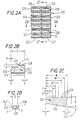
- Figs. 2A-2D show a known cutting insert 320 with a body 325 and four sides 321, 322, 323, and 324.
- the body 325 is shown as rectangular with rounded corners, (as viewed from above), but it may be any desired shape, e.g. square, circular, oval, elliptical, triangular, or trapezoidal.
- the top surface of the body 325 has two cutting surfaces 326 and 327 each with a plurality of chipbreakers 328 formed therein with ridges 329 therebetween.
- a typical cutting insert 320 may have the following dimensions:
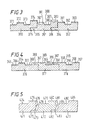
- Fig. 3 shows cutting inserts 360, 361, and 362 in an array.
- the cutting insert 360 has four cutting surfaces 371, 372, 373, 374 and a tab receiving recess 375.
- the cutting insert 361 has three cutting surfaces 381, 382, 383, and 384 each with a chipbreaker indentation; a tab 385; and a tab receiving recess 386.
- the cutting insert 361 has different depth chipbreakers 387 and 388 in its milling surfaces and all milling surfaces are at different levels.
- the tab 385 is positioned in the tab receiving recess 375 of the cutting insert 360.
- the cutting insert 362 has three cutting surfaces 391, 392, 393 each with a chipbreaker indentation and a tab 394 that is positioned in the tab receiving recess 386 of the insert 361.
- the cutting insert 361 may be omitted from the pattern of Fig. 3. Alternatively, multiple cutting inserts 361 may be used.
- any insert and a tab receiving recess on any cutting insert. It is within the scope of this invention for the tab to be at any level on the insert (as viewed from the side in Fig. 3); to be on any side of the cutting insert; and for a tab receiving recess to be anywhere on a cutting insert suitable for positioning therein of a tab. Also the extent of the tab (side-to-side in Fig. 3) may be any desired length with a corresponding tab receiving recess.
- the tab members may extend across the entire width of a cutting insert or only partially thereacross. Any tab may have a chip breaking indentation or part thereof.
- Fig. 4 shows cutting inserts 376, 377 and 378 in an array.
- the cutting insert 376 has cutting surfaces 363, 364, and 365 each with a chipbreaker 366.
- the cutting insert 377 has a tab 367 with a chipbreaker indentation 368; a cutting surface 369 with a chipbreaker indentation 389; a cutting surface 395 with a chipbreaker indentation 396; and a step surface 397 over which a tab is positionable.
- the cutting insert 378 has a tab 398 that overlies the step surface 397; a cutting surface 399; a chipbreaker 355 on the tab 398 and on the milling surface 399; a cutting surface 356; a cutting surface 357; and chinbreakers 358.
- Fig. 5 shows cutting inserts 471, 472 and 473 in an array.
- the cutting insert 471 has a cutting surface 474; a cutting surface 475; a tapered end 476; and a recess 477.
- the cutting insert 472 has a tab 473 part of which is in the tab recess 477; a tapered end 478; a cutting surface 479; a cutting surface 480; a tapered end 481 and a tab recess 482.
- the cutting insert 473 has a tab 483 part of which is in the tab recess 482; a tapered end 484; a cutting surface 488; and a milling surface 486.
- Cutting inserts according to the present invention as in Fig. 5 may have one, three, four or more cutting surfaces with or without one or more chipbreakers.
- tabs and recesses may be used to achieve desired spacing and matrix material and/or milling matrix material may be emplaced in any space between cutting inserts.
- Tabs, and/or recesses may be used to achieve proper arrangement, alignment, and orientation (one cutting insert with respect to another as well as various rake angles) of cutting inserts on milling bodies or on milling blades.
- Cutting inserts disclosed herein may be applied by any known application method in any known combination, pattern, array or arrangement.
- Figs. 6A and 6B show a cutting insert 420 having a tab 421 projecting from one of its sides.
- the cutting insert 420 with the tab 421 may be used with any cutting insert disclosed herein to space the cutting insert 420 apart from another insert with the tab 421 abutting the other insert.
- the tab 421 may be positioned in a corresponding recess of another insert, either with a tight fit or a loose fit, depending on abutment or spacing desired between the cutting inserts.
- Figs. 6C and 6D show a cutting insert 430 with a tab insert recess 431 for receiving a tab like the tab 421 of the insert 420.
- Fig. 6E shows an array of cutting inserts 420 and 430.
- an array of interlinked cutting inserts is provided, such as the array 450 of Fig. 6A that includes a cutting insert 451 (Fig.
- FIG. 6B A minimum space is shown between cutting inserts in the array 450, but any desired spacing may be employed or the cutting inserts (or any pair of cutting inserts or group) may abut each other. In certain embodiments a plurality of cutting inserts are used adjacent each other and it is not desirable for the breaking of one cutting insert to result in the breaking of an adjacent cutting insert.
- the tab may have a weakening groove, cut, or indentation (which may or may not be one or more chipbreakers).
- the chipbreaker indentation 368 of the tab 367 may be of sufficient size to render the step member a "breakaway" member if force applied to the cutting insert 376 is sufficient to break the cutting insert 376.
- the tab can be used to determine the spacing between adjacent cutting inserts the primary function of the tab is to allow adjacent cutting inserts to support one another and prevent inadvertent dislocation from a given position.
- Figs. 8A-8D show a cutting insert 340 with a body 345 and four sides 341, 342, 342, and 344.
- the cutting inserts 340 shown from above as rectangular may be any desired shape.
- the top surface of the body 345 has four cutting surfaces 351, 352, 353, and 354 each with a plurality of chipbreakers 348 formed therein with ridges 349 therebetween.
- One particular embodiment of the insert 340 has the following dimensions:
- cutting is intended to include “milling”.
Landscapes
- Life Sciences & Earth Sciences (AREA)
- Engineering & Computer Science (AREA)
- Geology (AREA)
- Mining & Mineral Resources (AREA)
- Physics & Mathematics (AREA)
- Environmental & Geological Engineering (AREA)
- Fluid Mechanics (AREA)
- General Life Sciences & Earth Sciences (AREA)
- Geochemistry & Mineralogy (AREA)
- Milling Processes (AREA)
Claims (17)
- Plaquette de coupe (320, 361) destinée à être utilisée dans une fraise d'un puits de forage, caractérisée en ce que ladite plaquette de coupe comporte un moyen (T, U, 375, 385) coopérant avec une autre plaquette de coupe pour empêcher un déplacement intempestif correspondant.
- Plaquette de coupe selon la revendication 1, dans laquelle ledit moyen comprend une première surface inclinée et une deuxième surface inclinée, l'angle (T) de la première surface inclinée étant différent de l'angle (U) de la deuxième surface inclinée.
- Plaquette de coupe (361) selon la revendication 1, dans laquelle ledit moyen comprend une patte (385).
- Plaquette de coupe (361) selon les revendications 1 ou 3, dans laquelle ledit moyen comprend une entaille (375) destinée à recevoir une patte d'une plaquette de coupe adjacente.
- Plaquette de coupe selon les revendications 3 ou 4, dans laquelle ledit moyen comprend un évidement destiné à recevoir une patte d'une plaquette de coupe adjacente.
- Plaquette de coupe (472) selon l'une quelconque des revendications 1, 3, 4 ou 5, dans laquelle ledit moyen comprend en outre une surface inclinée (478).
- Plaquette de coupe selon la revendication 1, englobant une base rectangulaire comportant quatre côtés, dont au moins deux comportent ledit moyen.
- Plaquette de coupe selon la revendication 7, dans laquelle chaque côté comporte ledit moyen.
- Plaquette de coupe (340) selon l'une quelconque des revendications précédentes, ladite plaquette de coupe (340) comprenant un corps (345) comportant une base pouvant être montée sur une surface de ladite fraise du puits de forage, et une surface de coupe (351) délimitée par des limites linéaires s'étendant d'une première arête de la plaquette de coupe vers une deuxième arête correspondante, ladite surface de coupe (351) comportant plusieurs nervures (349) s'étendant entre lesdites limites linéaires, caractérisée par quatre surfaces de coupe (351, 352, 353, 354), les limites linéaires correspondantes étant pratiquement parallèles les unes aux autres.
- Plaquette de coupe (340) selon la revendication 9, dans laquelle au moins une desdites surfaces de coupe (352) est agencée à une distance de la base différente de celle de l'autre (des autres) surface(s) de coupe (351).
- Plaquette de coupe selon les revendications 9 ou 10, comprenant en outre plusieurs entailles brise-copeaux sur chaque surface de coupe.
- Plaquette de coupe selon la revendication 11, dans laquelle lesdites entailles brise-copeaux ont une forme ovale, vues d'en haut.
- Plaquette de coupe selon les revendications 11 ou 12, dans laquelle lesdites plusieurs entailles brise-copeaux sont constituées par un ensemble configuré de rangées et de colonnes d'entailles recouvrant pratiquement l'ensemble des surfaces de coupe.
- Plaquette de coupe selon la revendication 10 ou selon l'une quelconque des revendications dépendant directement ou indirectement de celle-ci, dans laquelle une des surfaces de coupe déborde au-delà de l'autre (des autres) surfaces) de coupe d'une distance comprise entre environ 0,7 mm (0,03") et environ 2,3 mm (0,09").
- Plaquette de coupe selon l'une quelconque des revendications 9 à 14, dans laquelle ladite base est rectangulaire.
- Plaquette de coupe selon la revendication 15, dans laquelle ladite base est carrée.
- Outil de coupe pour un puits de forage comportant une plaquette de coupe selon l'une quelconque des revendications 9 à 15.
Applications Claiming Priority (3)
| Application Number | Priority Date | Filing Date | Title |
|---|---|---|---|
| US846092 | 1997-05-01 | ||
| US08/846,092 US5908071A (en) | 1995-09-22 | 1997-05-01 | Wellbore mills and inserts |
| PCT/GB1998/001117 WO1998050671A1 (fr) | 1997-05-01 | 1998-05-01 | Piece rapportee tranchante destinee a une fraise de meulage d'un puits de forage |
Publications (2)
| Publication Number | Publication Date |
|---|---|
| EP0979344A1 EP0979344A1 (fr) | 2000-02-16 |
| EP0979344B1 true EP0979344B1 (fr) | 2002-08-28 |
Family
ID=25296919
Family Applications (1)
| Application Number | Title | Priority Date | Filing Date |
|---|---|---|---|
| EP98919299A Expired - Lifetime EP0979344B1 (fr) | 1997-05-01 | 1998-05-01 | Piece rapportee tranchante destinee a une fraise de meulage d'un puits de forage |
Country Status (6)
| Country | Link |
|---|---|
| US (1) | US5908071A (fr) |
| EP (1) | EP0979344B1 (fr) |
| AU (1) | AU7218198A (fr) |
| CA (1) | CA2287949C (fr) |
| DE (1) | DE69807461T2 (fr) |
| WO (1) | WO1998050671A1 (fr) |
Families Citing this family (16)
| Publication number | Priority date | Publication date | Assignee | Title |
|---|---|---|---|---|
| US5984005A (en) * | 1995-09-22 | 1999-11-16 | Weatherford/Lamb, Inc. | Wellbore milling inserts and mills |
| US6170576B1 (en) | 1995-09-22 | 2001-01-09 | Weatherford/Lamb, Inc. | Mills for wellbore operations |
| US6568492B2 (en) | 2001-03-02 | 2003-05-27 | Varel International, Inc. | Drag-type casing mill/drill bit |
| DE10131357A1 (de) * | 2001-06-28 | 2003-01-16 | Fette Wilhelm Gmbh | Schneidwerkzeug mit Schnittaufteilung |
| US7108064B2 (en) * | 2002-10-10 | 2006-09-19 | Weatherford/Lamb, Inc. | Milling tool insert and method of use |
| AT7804U1 (de) * | 2004-02-11 | 2005-09-26 | Ceratizit Austria Gmbh | Klingenförmiger schneideinsatz und werkzeug für seine verwendung |
| DE102004016819B3 (de) * | 2004-04-05 | 2005-08-18 | Hilti Ag | Schneidsegment für Werkzeuge |
| US7425108B2 (en) * | 2006-04-21 | 2008-09-16 | Laszlo Frecska | Method for milling splines |
| US9022117B2 (en) | 2010-03-15 | 2015-05-05 | Weatherford Technology Holdings, Llc | Section mill and method for abandoning a wellbore |
| US8662208B2 (en) | 2010-06-17 | 2014-03-04 | American National Carbide Co. | Downhole cutting tool, cutting elements and method |
| US9512690B2 (en) | 2012-12-18 | 2016-12-06 | Smith International, Inc. | Milling cutter having undulating chip breaker |
| US9938781B2 (en) | 2013-10-11 | 2018-04-10 | Weatherford Technology Holdings, Llc | Milling system for abandoning a wellbore |
| US10260302B2 (en) | 2014-06-25 | 2019-04-16 | Schlumberger Technology Corporation | Cutting insert for initiating a cutout |
| US10392868B2 (en) * | 2015-09-30 | 2019-08-27 | Schlumberger Technology Corporation | Milling wellbore casing |
| US11697181B2 (en) | 2020-01-27 | 2023-07-11 | Weatherford Technology Holdings, Llc | Fusible metal clay, structures formed therefrom, and associated methods |
| JP7282824B2 (ja) * | 2021-03-31 | 2023-05-29 | 本田技研工業株式会社 | 切削工具 |
Family Cites Families (94)
| Publication number | Priority date | Publication date | Assignee | Title |
|---|---|---|---|---|
| US1522593A (en) * | 1919-10-13 | 1925-01-13 | Rowland O Pickin | Rotary drilling tool |
| US1681675A (en) * | 1925-05-16 | 1928-08-21 | Frank P Miller | Rotary cutter |
| US2333653A (en) * | 1942-01-16 | 1943-11-09 | Charles E Kraus | Rotary cutter |
| US2328494A (en) * | 1942-05-07 | 1943-08-31 | O K Tool Co Inc | Milling cutter |
| US2370273A (en) * | 1943-05-20 | 1945-02-27 | Edward A Ulliman | Cutter |
| DE1070898B (fr) * | 1958-04-09 | |||
| US2975507A (en) * | 1958-07-10 | 1961-03-21 | Byron Nichols E | Milling cutter |
| DE1477374C3 (de) * | 1962-03-20 | 1974-02-21 | Hans 8502 Zirndorf Heinlein | Schneidwerkzeug für die spanabhebende Bearbeitung |
| US3381349A (en) * | 1966-04-25 | 1968-05-07 | Newcomer Prod Inc | Cutting tool |
| US3636602A (en) * | 1969-07-11 | 1972-01-25 | Frank Owen | Cutting tools |
| US3701187A (en) * | 1970-12-15 | 1972-10-31 | Ingersoll Milling Machine Co | Slotting cutter and indexable inserts therefor |
| US3875631A (en) * | 1972-08-15 | 1975-04-08 | Paul Malinchak | Inserts for metal cutters |
| US3947937A (en) * | 1973-11-16 | 1976-04-06 | Karl Hertel | Control groove in cutting elements for metal working tools |
| ES207422Y (es) * | 1974-11-13 | 1976-07-01 | Th. Kieserling & Albrecht | Un util de corte con filo principal y otro secundario. |
| US4068976A (en) * | 1976-06-29 | 1978-01-17 | Kennametal Inc. | Cutting insert configuration |
| US4119151A (en) * | 1977-02-25 | 1978-10-10 | Homco International, Inc. | Casing slotter |
| US4140431A (en) * | 1977-11-18 | 1979-02-20 | Kennametal Inc. | Cutting insert |
| DE2825748A1 (de) * | 1978-06-12 | 1979-12-13 | Roechling Burbach Weiterverarb | Vorrichtung zum schaelen bzw. wellendrehen |
| FR2431897A1 (fr) * | 1978-07-25 | 1980-02-22 | Igman Sa | Plaquette rapportee pour outil de coupe rotatif |
| US4335984A (en) * | 1980-11-05 | 1982-06-22 | Raymond Zweekly | Metalcutting insert for roughing and finishing |
| US4340325A (en) * | 1980-12-23 | 1982-07-20 | General Electric Co. | Cutting insert for deep grooving |
| US4629372A (en) * | 1981-02-02 | 1986-12-16 | Manchester Tool Company | Chip-controlling insert |
| US4449864A (en) * | 1981-12-07 | 1984-05-22 | Sazzadul Haque | Consumable self-regenerative ledge cutting insert |
| US4472093A (en) * | 1982-03-22 | 1984-09-18 | Hamilton Martin N | Scalloped helical blade cutter |
| SE437228B (sv) * | 1982-05-17 | 1985-02-18 | Santrade Ltd | Sker for spanskerande bearbetning |
| US4583431A (en) * | 1982-11-03 | 1986-04-22 | General Electric Company | Self-sharpening coated tool constructions |
| US4588332A (en) * | 1982-11-03 | 1986-05-13 | General Electric Company | Self-sharpening tool constructions having chip-grooves |
| US4552492A (en) * | 1983-02-18 | 1985-11-12 | General Electric Company | Cutting insert with means for simultaneously removing a plurality of chips |
| US4593777A (en) * | 1983-02-22 | 1986-06-10 | Nl Industries, Inc. | Drag bit and cutters |
| SE454331B (sv) * | 1984-03-26 | 1988-04-25 | Santrade Ltd | Verktyg och sker for bearbetning av kompositmaterial |
| JPS60178504U (ja) * | 1984-05-07 | 1985-11-27 | 住友電気工業株式会社 | スロ−アウエイチツプ |
| US4618009A (en) * | 1984-08-08 | 1986-10-21 | Homco International Inc. | Reaming tool |
| US4606678A (en) * | 1985-04-22 | 1986-08-19 | Gte Valeron Corporation | Circular chip control insert |
| USD298633S (en) | 1985-08-21 | 1988-11-22 | Kenemore Marvin E | Cutting tool |
| US4796709A (en) * | 1986-01-06 | 1989-01-10 | Tri-State Oil Tool Industries, Inc. | Milling tool for cutting well casing |
| US5086838A (en) * | 1986-01-06 | 1992-02-11 | Baker Hughes Incorporated | Tapered cutting tool for reaming tubular members in well bore |
| US5373900A (en) * | 1988-04-15 | 1994-12-20 | Baker Hughes Incorporated | Downhole milling tool |
| US5150755A (en) * | 1986-01-06 | 1992-09-29 | Baker Hughes Incorporated | Milling tool and method for milling multiple casing strings |
| US4938291A (en) * | 1986-01-06 | 1990-07-03 | Lynde Gerald D | Cutting tool for cutting well casing |
| US4978260A (en) * | 1986-01-06 | 1990-12-18 | Tri-State Oil Tools, Inc. | Cutting tool for removing materials from well bore |
| US5038859A (en) * | 1988-04-15 | 1991-08-13 | Tri-State Oil Tools, Inc. | Cutting tool for removing man-made members from well bore |
| US5014778A (en) * | 1986-01-06 | 1991-05-14 | Tri-State Oil Tools, Inc. | Milling tool for cutting well casing |
| US4887668A (en) * | 1986-01-06 | 1989-12-19 | Tri-State Oil Tool Industries, Inc. | Cutting tool for cutting well casing |
| US4717290A (en) * | 1986-12-17 | 1988-01-05 | Homco International, Inc. | Milling tool |
| US4705434A (en) * | 1986-12-22 | 1987-11-10 | Gte Valenite | Scalloped polygonal cutting insert |
| DE8700393U1 (de) * | 1987-01-09 | 1988-05-05 | Nederlandse Hardmetaal Fabrieken B.V., Arnhem | Schneidwerkzeug für die spanabhebende Metallbearbeitung |
| US4872520A (en) * | 1987-01-16 | 1989-10-10 | Triton Engineering Services Company | Flat bottom drilling bit with polycrystalline cutters |
| DE3713161C3 (de) * | 1987-04-17 | 1994-07-28 | Walter Ag | Wendeschneidplatte für ein Bohrfräswerkzeug |
| CH671901A5 (fr) * | 1987-06-25 | 1989-10-13 | Stellram Sa | |
| US4854785A (en) * | 1987-08-17 | 1989-08-08 | Gte Valenite Corporation | Scalloped threader cutting insert |
| SU1579639A1 (ru) * | 1988-01-12 | 1990-07-23 | Краматорский Индустриальный Институт | Режуща многогранна пластина |
| US5158401A (en) * | 1988-03-21 | 1992-10-27 | Gte Valenite Corporation | Indexable insert for roughing and finishing |
| US5028175A (en) * | 1988-03-21 | 1991-07-02 | Gte Valenite Corporation | Indexable insert for roughing and finishing |
| USD317010S (en) | 1988-05-11 | 1991-05-21 | General Electric Company | Stud-mounted polycrystalline toothed diamond cutting blank |
| FR2636870B1 (fr) * | 1988-09-29 | 1994-05-13 | Safety Sa | Insert de coupe |
| GB8903075D0 (en) * | 1989-02-10 | 1989-03-30 | Iscar Hartmetall | A cutting insert |
| GB8904251D0 (en) * | 1989-02-24 | 1989-04-12 | Smith Int North Sea | Downhole milling tool and cutter therefor |
| USD330206S (en) | 1989-03-24 | 1992-10-13 | General Electric Company | Stud-mounted polycrystalline diamond cutting blank |
| US4911254A (en) * | 1989-05-03 | 1990-03-27 | Hughes Tool Company | Polycrystalline diamond cutting element with mating recess |
| JP2501471Y2 (ja) * | 1989-08-23 | 1996-06-19 | 三菱マテリアル株式会社 | 転削工具用スロ―アウェイチップ |
| GB8920227D0 (en) * | 1989-09-07 | 1989-10-18 | Iscar Hartmetall | A cutting insert |
| IL91575A (en) * | 1989-09-08 | 1992-07-15 | Iscar Ltd | Cutting insert having a chip former |
| DE8913805U1 (de) * | 1989-11-23 | 1991-03-21 | Hertel AG Werkzeuge + Hartstoffe, 8510 Fürth | Stechdrehwerkzeug |
| GB9003047D0 (en) * | 1990-02-10 | 1990-04-11 | Tri State Oil Tool Uk | Insert type window mill |
| US5059069A (en) * | 1990-02-09 | 1991-10-22 | Sandvik Ab | Insert for thread cutting |
| GB9022062D0 (en) * | 1990-10-10 | 1990-11-21 | Petco Fishing & Rental Tools U | Milling tool |
| EP0480576B1 (fr) * | 1990-10-10 | 1995-06-07 | Iscar Ltd. | Une plaquette de coupe pour une fraise |
| US5112162A (en) * | 1990-12-20 | 1992-05-12 | Advent Tool And Manufacturing, Inc. | Thread milling cutter assembly |
| US5253710A (en) * | 1991-03-19 | 1993-10-19 | Homco International, Inc. | Method and apparatus to cut and remove casing |
| USD337335S (en) | 1991-08-22 | 1993-07-13 | Kennametal Inc. | Cutting tool insert |
| US5209611A (en) * | 1991-09-20 | 1993-05-11 | Duramet Corporation | Cutting insert having dual cutting edges on one surface and holding body for insert |
| GB9120298D0 (en) * | 1991-09-24 | 1991-11-06 | Homco International Inc | Casing cutting and retrieving tool |
| US5180258A (en) * | 1991-09-30 | 1993-01-19 | Gte Valenite Corporation | High feed heavy depth of cut insert for the aluminum wheel turning market |
| US5221164A (en) * | 1992-08-03 | 1993-06-22 | Gte Valenite Corporation | Positive rake insert having serrations for cutting |
| GB2270097A (en) * | 1992-09-01 | 1994-03-02 | Red Baron | Cutting element for use on a mill |
| US5341873A (en) * | 1992-09-16 | 1994-08-30 | Weatherford U.S., Inc. | Method and apparatus for deviated drilling |
| DE4395361T1 (de) * | 1992-10-19 | 1994-11-10 | Baker Hughes Inc | Wiederausbaubares Richtkeilsystem |
| DE4239235A1 (de) * | 1992-11-21 | 1994-05-26 | Krupp Widia Gmbh | Schneideinsatz |
| AU670642B2 (en) * | 1992-12-23 | 1996-07-25 | De Beers Industrial Diamond Division (Proprietary) Limited | Tool component |
| GB2280692B (en) * | 1993-08-05 | 1996-09-25 | Red Baron | Improvements in or relating to a milling insert and a milling tool |
| US5452759A (en) * | 1993-09-10 | 1995-09-26 | Weatherford U.S., Inc. | Whipstock system |
| US5429187A (en) * | 1994-03-18 | 1995-07-04 | Weatherford U.S., Inc. | Milling tool and operations |
| US5425417A (en) * | 1993-09-10 | 1995-06-20 | Weatherford U.S., Inc. | Wellbore tool setting system |
| DE4342557C2 (de) * | 1993-12-14 | 1996-04-11 | Felix Leeb | Fräsbohrwerkzeug |
| US5757911A (en) * | 1994-03-10 | 1998-05-26 | Mita Industrial Co., Ltd. | Encryption communication process and terminal for encryption communication |
| US5449255A (en) * | 1994-03-11 | 1995-09-12 | Valenite Inc. | Cutting insert having multiple chip breaker surfaces |
| SE509224C2 (sv) * | 1994-05-19 | 1998-12-21 | Sandvik Ab | Vändskär |
| GB2295172B (en) * | 1994-11-21 | 1998-08-19 | Red Baron | Improvements in or relating to a milling insert and a milling tool |
| US5626189A (en) * | 1995-09-22 | 1997-05-06 | Weatherford U.S., Inc. | Wellbore milling tools and inserts |
| US5706906A (en) * | 1996-02-15 | 1998-01-13 | Baker Hughes Incorporated | Superabrasive cutting element with enhanced durability and increased wear life, and apparatus so equipped |
| US5791422A (en) * | 1996-03-12 | 1998-08-11 | Smith International, Inc. | Rock bit with hardfacing material incorporating spherical cast carbide particles |
| US5788001A (en) * | 1996-04-18 | 1998-08-04 | Camco Drilling Group Limited Of Hycalog | Elements faced with superhard material |
| US5791423A (en) * | 1996-08-02 | 1998-08-11 | Baker Hughes Incorporated | Earth-boring bit having an improved hard-faced tooth structure |
| US5791409A (en) * | 1996-09-09 | 1998-08-11 | Baker Hughes Incorporated | Hydro-mechanical multi-string cutter |
-
1997
- 1997-05-01 US US08/846,092 patent/US5908071A/en not_active Expired - Lifetime
-
1998
- 1998-05-01 DE DE69807461T patent/DE69807461T2/de not_active Expired - Fee Related
- 1998-05-01 AU AU72181/98A patent/AU7218198A/en not_active Abandoned
- 1998-05-01 WO PCT/GB1998/001117 patent/WO1998050671A1/fr not_active Ceased
- 1998-05-01 EP EP98919299A patent/EP0979344B1/fr not_active Expired - Lifetime
- 1998-05-01 CA CA002287949A patent/CA2287949C/fr not_active Expired - Fee Related
Also Published As
| Publication number | Publication date |
|---|---|
| EP0979344A1 (fr) | 2000-02-16 |
| WO1998050671A1 (fr) | 1998-11-12 |
| CA2287949A1 (fr) | 1998-11-12 |
| US5908071A (en) | 1999-06-01 |
| AU7218198A (en) | 1998-11-27 |
| DE69807461D1 (de) | 2002-10-02 |
| CA2287949C (fr) | 2005-12-06 |
| DE69807461T2 (de) | 2003-04-24 |
Similar Documents
| Publication | Publication Date | Title |
|---|---|---|
| EP0979344B1 (fr) | Piece rapportee tranchante destinee a une fraise de meulage d'un puits de forage | |
| EP0494646B1 (fr) | Plaquette de coupe à contrÔle de copeaux | |
| US6599061B1 (en) | Cutting insert with radially aligned chip forming grooves | |
| KR101345519B1 (ko) | 밀링 커터, 밀링 커터 몸체 및 절두 피라미드 형태의인덱서블 절삭 인서트 | |
| EP0582222B1 (fr) | Plaquette de coupe avec angle de dépouille positif et avec des entailles | |
| KR100437433B1 (ko) | 금속 절삭 가공용 절삭 삽입체 및 홀더 | |
| JP3607288B2 (ja) | チップ制御手段付き切削インサート | |
| KR101541936B1 (ko) | 칩 제거 기계가공용 절삭 인서트 및 공구 | |
| KR101240805B1 (ko) | 접선 절단 삽입체 및 밀링 절단기 | |
| EP2403675B1 (fr) | Insert de coupe avec surface évidée de support d'insert, et outil de coupe | |
| US7374372B2 (en) | Indexable insert | |
| EP0117242B1 (fr) | Dispositif de filetage | |
| SE0100053L (sv) | Vändbart frässkär | |
| EP0921882B1 (fr) | Outil de coupe et plaquette amovible a utiliser avec celui-ci | |
| AU2188895A (en) | A cutting insert | |
| EP1108489B1 (fr) | Fraise et sa plaquette de coupe | |
| CA2231875A1 (fr) | Plaquette de coupe pour fraisage | |
| CA2485654A1 (fr) | Plaquette de coupe tangentielle et fraise | |
| AU720053B2 (en) | A cutting insert for use in a wellbore milling tool | |
| KR19990029059A (ko) | 금속 절삭용 공구 | |
| KR20060050825A (ko) | 인서트 시트 | |
| EP0205977A3 (fr) | Plaquette de coupe à guidage du copeau | |
| JPH02180508A (ja) | 両面利用切削インサート | |
| EP1425126B1 (fr) | Piece rapportee coupante | |
| JPH0134729B2 (fr) |
Legal Events
| Date | Code | Title | Description |
|---|---|---|---|
| PUAI | Public reference made under article 153(3) epc to a published international application that has entered the european phase |
Free format text: ORIGINAL CODE: 0009012 |
|
| 17P | Request for examination filed |
Effective date: 19991105 |
|
| AK | Designated contracting states |
Kind code of ref document: A1 Designated state(s): DE FR GB IT NL |
|
| 17Q | First examination report despatched |
Effective date: 20010810 |
|
| GRAG | Despatch of communication of intention to grant |
Free format text: ORIGINAL CODE: EPIDOS AGRA |
|
| GRAG | Despatch of communication of intention to grant |
Free format text: ORIGINAL CODE: EPIDOS AGRA |
|
| GRAH | Despatch of communication of intention to grant a patent |
Free format text: ORIGINAL CODE: EPIDOS IGRA |
|
| GRAH | Despatch of communication of intention to grant a patent |
Free format text: ORIGINAL CODE: EPIDOS IGRA |
|
| RAP1 | Party data changed (applicant data changed or rights of an application transferred) |
Owner name: WEATHERFORD/LAMB, INC. |
|
| GRAA | (expected) grant |
Free format text: ORIGINAL CODE: 0009210 |
|
| AK | Designated contracting states |
Kind code of ref document: B1 Designated state(s): DE FR GB IT NL |
|
| PG25 | Lapsed in a contracting state [announced via postgrant information from national office to epo] |
Ref country code: IT Free format text: LAPSE BECAUSE OF FAILURE TO SUBMIT A TRANSLATION OF THE DESCRIPTION OR TO PAY THE FEE WITHIN THE PRESCRIBED TIME-LIMIT;WARNING: LAPSES OF ITALIAN PATENTS WITH EFFECTIVE DATE BEFORE 2007 MAY HAVE OCCURRED AT ANY TIME BEFORE 2007. THE CORRECT EFFECTIVE DATE MAY BE DIFFERENT FROM THE ONE RECORDED. Effective date: 20020828 |
|
| REG | Reference to a national code |
Ref country code: GB Ref legal event code: FG4D |
|
| REF | Corresponds to: |
Ref document number: 69807461 Country of ref document: DE Date of ref document: 20021002 |
|
| ET | Fr: translation filed | ||
| PGFP | Annual fee paid to national office [announced via postgrant information from national office to epo] |
Ref country code: FR Payment date: 20030508 Year of fee payment: 6 Ref country code: DE Payment date: 20030508 Year of fee payment: 6 |
|
| PGFP | Annual fee paid to national office [announced via postgrant information from national office to epo] |
Ref country code: NL Payment date: 20030530 Year of fee payment: 6 |
|
| PLBE | No opposition filed within time limit |
Free format text: ORIGINAL CODE: 0009261 |
|
| STAA | Information on the status of an ep patent application or granted ep patent |
Free format text: STATUS: NO OPPOSITION FILED WITHIN TIME LIMIT |
|
| 26N | No opposition filed |
Effective date: 20030530 |
|
| PG25 | Lapsed in a contracting state [announced via postgrant information from national office to epo] |
Ref country code: NL Free format text: LAPSE BECAUSE OF NON-PAYMENT OF DUE FEES Effective date: 20041201 Ref country code: DE Free format text: LAPSE BECAUSE OF NON-PAYMENT OF DUE FEES Effective date: 20041201 |
|
| PG25 | Lapsed in a contracting state [announced via postgrant information from national office to epo] |
Ref country code: FR Free format text: LAPSE BECAUSE OF NON-PAYMENT OF DUE FEES Effective date: 20050131 |
|
| NLV4 | Nl: lapsed or anulled due to non-payment of the annual fee |
Effective date: 20041201 |
|
| REG | Reference to a national code |
Ref country code: FR Ref legal event code: ST |
|
| REG | Reference to a national code |
Ref country code: GB Ref legal event code: 732E Free format text: REGISTERED BETWEEN 20151022 AND 20151028 |
|
| PGFP | Annual fee paid to national office [announced via postgrant information from national office to epo] |
Ref country code: GB Payment date: 20160427 Year of fee payment: 19 |
|
| GBPC | Gb: european patent ceased through non-payment of renewal fee |
Effective date: 20170501 |
|
| PG25 | Lapsed in a contracting state [announced via postgrant information from national office to epo] |
Ref country code: GB Free format text: LAPSE BECAUSE OF NON-PAYMENT OF DUE FEES Effective date: 20170501 |