EP0979351B1 - Verfahren zum regeln der aufladung einer brennkraftmaschine - Google Patents
Verfahren zum regeln der aufladung einer brennkraftmaschine Download PDFInfo
- Publication number
- EP0979351B1 EP0979351B1 EP97949969A EP97949969A EP0979351B1 EP 0979351 B1 EP0979351 B1 EP 0979351B1 EP 97949969 A EP97949969 A EP 97949969A EP 97949969 A EP97949969 A EP 97949969A EP 0979351 B1 EP0979351 B1 EP 0979351B1
- Authority
- EP
- European Patent Office
- Prior art keywords
- value
- correction value
- ldimxa
- ldimxaa
- ldimx
- Prior art date
- Legal status (The legal status is an assumption and is not a legal conclusion. Google has not performed a legal analysis and makes no representation as to the accuracy of the status listed.)
- Expired - Lifetime
Links
Images



Classifications
-
- F—MECHANICAL ENGINEERING; LIGHTING; HEATING; WEAPONS; BLASTING
- F02—COMBUSTION ENGINES; HOT-GAS OR COMBUSTION-PRODUCT ENGINE PLANTS
- F02D—CONTROLLING COMBUSTION ENGINES
- F02D23/00—Controlling engines characterised by their being supercharged
-
- F—MECHANICAL ENGINEERING; LIGHTING; HEATING; WEAPONS; BLASTING
- F02—COMBUSTION ENGINES; HOT-GAS OR COMBUSTION-PRODUCT ENGINE PLANTS
- F02D—CONTROLLING COMBUSTION ENGINES
- F02D45/00—Electrical control not provided for in groups F02D41/00 - F02D43/00
-
- F—MECHANICAL ENGINEERING; LIGHTING; HEATING; WEAPONS; BLASTING
- F02—COMBUSTION ENGINES; HOT-GAS OR COMBUSTION-PRODUCT ENGINE PLANTS
- F02D—CONTROLLING COMBUSTION ENGINES
- F02D41/00—Electrical control of supply of combustible mixture or its constituents
- F02D41/0002—Controlling intake air
- F02D41/0007—Controlling intake air for control of turbo-charged or super-charged engines
-
- F—MECHANICAL ENGINEERING; LIGHTING; HEATING; WEAPONS; BLASTING
- F02—COMBUSTION ENGINES; HOT-GAS OR COMBUSTION-PRODUCT ENGINE PLANTS
- F02D—CONTROLLING COMBUSTION ENGINES
- F02D41/00—Electrical control of supply of combustible mixture or its constituents
- F02D41/02—Circuit arrangements for generating control signals
- F02D41/14—Introducing closed-loop corrections
- F02D41/1401—Introducing closed-loop corrections characterised by the control or regulation method
- F02D2041/1409—Introducing closed-loop corrections characterised by the control or regulation method using at least a proportional, integral or derivative controller
-
- Y—GENERAL TAGGING OF NEW TECHNOLOGICAL DEVELOPMENTS; GENERAL TAGGING OF CROSS-SECTIONAL TECHNOLOGIES SPANNING OVER SEVERAL SECTIONS OF THE IPC; TECHNICAL SUBJECTS COVERED BY FORMER USPC CROSS-REFERENCE ART COLLECTIONS [XRACs] AND DIGESTS
- Y02—TECHNOLOGIES OR APPLICATIONS FOR MITIGATION OR ADAPTATION AGAINST CLIMATE CHANGE
- Y02T—CLIMATE CHANGE MITIGATION TECHNOLOGIES RELATED TO TRANSPORTATION
- Y02T10/00—Road transport of goods or passengers
- Y02T10/10—Internal combustion engine [ICE] based vehicles
- Y02T10/12—Improving ICE efficiencies
Definitions
- the invention relates to a method for regulating the charge an internal combustion engine, being from the control deviation between a target boost pressure and the actual boost pressure one Control value is generated, at least one by an integral controller has delivered part, and for the integral part a limit value is specified, which consists of one of several operating parameters of the internal combustion engine Basic value and a superimposed correction value is determined, according to claim 1, first part.
- the manipulated variable for the loader is composed of a proportional, a differential, and an integral part.
- the integral part is both in the stationary and also limited in dynamic operation of the internal combustion engine.
- the limit of the integral part in the dynamic Operation consists of a basic value that depends on Operating parameters are taken from characteristic curves and one correction value superimposed on the basic value.
- the correction value is dependent on the charge air temperature, the ambient pressure and the speed of the internal combustion engine adapted. More detailed information on the type of adaptation of the Correction values are not allowed for the mentioned publication remove.
- the invention is therefore based on the object of a method of the type mentioned at the beginning, which is a very robust Regulation of the charging of an internal combustion engine enables especially when extremely variable disturbances occur, e.g. very different boost pressure setpoints at full load or at very different speed dynamics.
- the correction value becomes adaptive depending determined by the speed, with several speed ranges are specified.
- the adapted correction value is gradually reduced when the control deviation is smaller than a threshold and the integral component is smaller than the current limit.
- a gradual increase of the adapted basic value takes place when the control deviation is greater than zero and the integral component is equal or greater than the current limit.
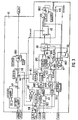
- the control deviation lde As can be seen from the functional diagram in FIG from a map KFLDPS depending on the engine speed nmot and the throttle valve position ⁇ Read the target boost pressure psoll. In addition, with a The pressure sensor in front of the throttle valve measured the actual boost pressure pvdk. In a node V1, the difference between the target boost pressure plsoll and the actual boost pressure pvdk determined. This difference is called the control deviation lde designated.
- the condition B_ldr is for an activation before the boost pressure control, a switch S1 is connected to the Output of node V1 placed so that at the output of the switch S1 as the control deviation lde the difference mentioned between the target boost pressure plsoll and the Actual boost pressure pvdk is present.
- the boost pressure control is not active, so the condition B_ldr does not exist, the Switch S1 to 0.0.
- the control deviation lde is in this So case zero.
- a threshold value decider SE1 applies one to the S input SR flip-flops FF a logic 1 if the system deviation lde a threshold exceeds UMDYLDR.
- the R entrance of the RS flip-flops FF is with the output of a comparator K1 connected.
- This comparator K1 outputs a logical 1, if the control deviation lde is less than or equal to 0.0.
- the output Q of the RS flip-flops FF a logical 1 if the control deviation lde the threshold UMDYLDR exceeds, that is, a Transition from stationary to dynamic operation.
- the flip-flop FF If there is a logical 1 at the R input of the RS flip-flop FF, that is, the control deviation lde is less than 0 (the Actual boost pressure is greater than the target boost pressure) the flip-flop FF reset and at its output Q there is a logical 0.
- the output signal B_lddy on Q output of the flip-flop FF indicates whether dynamic operation (logical 1) or stationary operation (logical 0) is.
- function block R1 depending on the operating condition B_lddy and the engine speed nmot a proportional ldrkp, a differential ldrkd and an integral control parameter ldrki determined.
- a differential component ldrdtv to the manipulated variable ldtv results from the product formation in the multiplier V3 between the differential control parameter ldrkd and the storage between the current control deviation lde and the one time cycle (approx. 50 ms) previously determined control deviation lde (i-1).
- the difference between the current control deviation lde and The previously determined control deviation lde (i-1) is in the connection point V4 formed.
- a delay element VZ1 delivers the control deviation delayed by one time cycle lde (i-1).
- the integral part lditv to the manipulated variable ldtv is one Integrator INT formed, which is the product of the integral control parameter ldrki and the delayed control deviation lde (i-1) and this product to the previous one Timing integral overlay lditv (i-1) superimposed.
- the integral component lditv is limited in order to Avoid overshoots when regulating the boost pressure.
- the limit value ldimx for the integral part lditv is in a switching block R2, which is shown below with reference to FIG is described, determined depending on the Control deviation lde, the integral part lditv, the Target boost pressure plsol, the engine speed nmot and the ratio between the target filling and the maximum filling of the Cylinder vrlsol.
- Function block R1 shown in FIG. 2 contains three Characteristic fields dependent on the engine speed nmot LDRQ1DY, LDRQ1ST and LDRQ2DY.
- switch S2 switches the integral controller parameter ldrki from the characteristic LDRQ1DY for dynamic Operation switched through to the output.
- From the counter S3 becomes the characteristic LDRQ2DY of the differential controller parameters ldrkd switched through to the output.
- the Proportional controller parameter ldrkp arises through difference formation at node V6 between a fixed value LDRQOD by a switch S4 to the node V6 is switched, and the differential controller parameter ldrkd.
- the condition is B_lddy for dynamic operation not given, but the machine is in stationary operation, then the integral controller parameter ldrki becomes off taken from the characteristic curve LDRQ1ST; accordingly lies now the switch S2 on the characteristic LDRQ1ST.
- the differential controller parameter ldrkd is set to 0.0 via switch SR3 and the proportional controller parameter ldrkp is set by the Switch S4 set to a fixed value LDRQOS.
- the fixed values LDRQOD, LDRQOS and the characteristic curves LDRQ1DY, LDRQ1ST and LDRQ2DY are applied by tests on the engine test bench in such a way that the charge control in dynamic and stationary Operating state is optimized.
- the function block R2 is shown, which from the engine speed nmot, the target boost pressure plsol, the Control deviation lde, the ratio of target filling to maximum filling the cylinder vrlsol and the integral part lditv the control value the limit value ldimx for the integral component lditv derives.
- the limit value ldimx consists of a basic value ldimxr and one superimposed on it in node V8 Correction value ldimxak.
- the limit value ldimx in link point 9 there is also a fixed predetermined value LDDIMX can be added. This value corresponds to LDDIMX a small fraction (approx. 0 ... 5%) of the limit value ldimx, which ensures that this small value is never undercut becomes.
- Is the current integral part larger than the limit without the safety margin Value LDDIMX so it can be done without raising the limit the boost pressure can be regulated spontaneously, provided that the to be regulated Boost pressure deviation not greater than the safety distance Is LDDIMX.
- a limit level BG1 limits the limit value ldimx a predeterminable value TVLDMX, which for example 95% of the Duty cycle of the manipulated variable for boost pressure control equivalent.
- the current correction value ldimxak for the limit value ldimx appears at the output of a summer SU.
- this summer SU becomes the correction value applied to its input 1 either gradually reduced under certain conditions or gradually increased.
- the charge control must be active, that is, the condition B_ldr must be set, and the current limit value ldimx must not be at the upper or lower end of the limit level BG1. Both information are present at the inputs of an AND gate AN1, which outputs a logic 1 to a further AND gate AN2 if the two conditions mentioned are met.
- Another condition is that the amount of the control deviation lde must be less than a threshold LDEIA.
- control deviation lde is fed to an amount image BB and then to a threshold value decider SE2, which outputs a logical 1 to the AND gate AN2 at its output if the amount of the control deviation lde is below the threshold LDEIA.
- This threshold LDEIA is almost 0.
- a threshold value decision SE3 is used to check whether the ratio of the target filling to the maximum filling the cylinder vrlsol lies above a threshold LDRVL. is that is the case, the machine is operated at full load and the threshold value decision SE3 gives a logical 1 to one Input of the AND gate AN2 from.
- the last condition that still needs to be fulfilled is that the integral part lditv is less than the limit ldimx.
- Comparator K2 accordingly compares the integral component lditv at the manipulated variable and the limit value ldimx before the connection point V9. Appears at the output of the comparator K2 a logical 1 if the integral component lditv is greater than the limit is ldimxr. Via an inverter NOT the output signal of the comparator K2 to an input of the AND gate AN2. Is at this input of the AND gate AN2 So a logical 1 if the integral part lditv is less than the limit ldimx.
- This condition B_ldimxn for a negative step-by-step correction of the correction value in the summer SU is in a delay element VZ2 delayed by a fixed debounce time TLDIAN Switch S5 and led to an OR gate OR1.
- the switch S5 connects the Input 4 of the summer SU with a read-only memory SP1, in which the step size LDDIAN for the negative tracking of the limit value is stored.
- the condition is B_ldimxn not fulfilled (corresponds to a logical 0 at the output of the AND gate AN2), the switch S5 switches to one Memory SP2 in which the step size LDDIAP for a positive Tracking of the limit value is stored.
- the output signal of the AND gate AN3, the condition B_ldimxp for the step-by-step positive correction of the correction value, is passed through a delay element VZ3, whose delay time is equal to a debounce time that from a characteristic curve dependent on the engine speed nmot TLDIAPN is taken.
- Its output signal, that is present at input 2 of the summer SU signals the summer SU whether a positive or negative step-by-step tracking of the one at its input 1 Limit should be made.
- the correction value present at the output of the summer SU ldimxak also becomes an input 5 of a function block AS supplied, in which the correction value is adapted. These adaptions are only made if, on the one hand Full load operation of the machine is given and the other Condition for a positive or a negative gradual Tracking the correction value is fulfilled.
- An information about the full load operation can at the output of the above Threshold decision SE3 can be tapped. The information on whether a positive or gradual The correction value can be updated using the output signal of the OR gate OR1 are removed. Either the output signal of the threshold decision SE3 as also the output signal of the OR gate OR1 Inputs of an AND gate AN4 supplied.
- condition B_ldimxa 1 is, the current value of the summer SU in a corresponding Memory cell of function block AS taken over, in which a multitude of simulating an adaptation characteristic Values is saved.
- Function block R3 also provides information B_stldw on change of support point.
- An input 1 of the summer SU for the formation of the correction value ldimxak becomes either the adapted correction value ldimxa from the output of the function block AS or an adapted Correction value ldimxaa supplied, in which in negative Jumps occurring in the direction are limited to a minimum value have been.
- the selection is made via a switch S6 between the adapted correction value ldmixa and the limited adapted correction value ldimxaa hit.
- the Switch S6 switches to the unlimited, adapted Correction value ldimxa at the start of activation of the charge pressure control, that is, immediately after one appears Rising edge of condition B_ldr for boost pressure control.
- a flip-flop recognizes the rising edge of the signal B_ldr AF. Otherwise the switch S6 is in the other position and leads the input 1 of the summer SU the limited adapted correction value ldimxaa.
- An input 3 of the summer SU receives one from the output OR gate OR2 the information whether a rising edge of the Boost pressure activation signal B_ldr is present or whether the signal B_stldw interpolation point change in function block R3 displays.
- the limited adapted correction value ldimxaa becomes as follows educated. From the one at the output of the function block AS applied adaptation correction value ldimxa is in one Junction point V10 is the current one output by the summer SU Correction value ldimxak subtracted.
- the difference signal ldimxad is supplied to a limit level BG2.
- the limit level BG2 limits negative jumps in the difference signal ldimxad to a predetermined limit LDMXNN.
- the limited difference signal ldimxab at the output of the limiter stage BG2 becomes the current correction value in node V11 ldimxak added again, so that from it finally the limited adapted correction value ldimxaa arises.
- FIG. 4 Like the support points sdldea, which the function block AS are supplied for the adaptation at the input 7, formed can be seen in Figure 4.
- four hysteresis generating circuit H1, H2, H3 and H4 are provided.
- Hysteresis constant LDHIA gives the hysteresis width in front.
- the hysteresis of the four circuits H1 to H4 are relative the speed nmot distributed so that any hysteresis covers one of four speed ranges. This speed-dependent
- the position of the individual hysteresis is determined by constants STLDIA1, STLDIA2, STLDIA3 and STLDIA4 the individual hysteresis circuits H1 to H4 specified.
- the current speed nmot is located at the output of the hysteresis circuit H1 or H2 or H3 or H4 a signal.
- Each of the output signals controls a switch S7, S8, S9 and S10.
- the switches S7, S8, S9 and S10 have five basic values 1.0, 2.0, 3.0, 4.0 and 5.0.
- the switch position that is depending on the current speed range nmot, one becomes of the five support points connected as output signal stldia and arrives at input 7 of the adaptation circuit AS.
- the slope increases the adaptation characteristic increases or decreases; the adapted Correction value ldimxa thus becomes larger or smaller through adaptation.
- the information about the change of base B is stldw obtained with the help of a comparator K3. This compares the current support point value stldia with the one time cycle previously determined interpolation point value stldia (i-1).
- a delay element VZ4 represents the previous base value stldia (i-1) ready for the comparator K3. Differ the two applied to the inputs of the comparator K3 Base values stldia and stldia (i-1) from each other, see above the comparator K3 gives information at its output Support point change B_stldw from.
Landscapes
- Engineering & Computer Science (AREA)
- Chemical & Material Sciences (AREA)
- Combustion & Propulsion (AREA)
- Mechanical Engineering (AREA)
- General Engineering & Computer Science (AREA)
- Combined Controls Of Internal Combustion Engines (AREA)
- Electrical Control Of Air Or Fuel Supplied To Internal-Combustion Engine (AREA)
- Supercharger (AREA)
- Output Control And Ontrol Of Special Type Engine (AREA)
Abstract
Description
Die Laderegelung muß aktiv sein, das heißt die Bedingung B_ldr muß gesetzt sein, und es darf der aktuelle Grenzwert ldimx nicht am oberen oder unteren Ende der Begrenzungsstufe BG1 liegen. Beide Informationen liegen an den Eingängen eines UND-Gatters AN1 an, das eine logische 1 an ein weiteres UND-Gatter AN2 abgibt, wenn die genannten zwei Bedingungen erfüllt sind. Eine weitere Bedingung besteht darin, daß der Betrag der Regelabweichung lde kleiner einer Schwelle LDEIA sein muß. Dazu wird die Regelabweichung lde einem Betragsbilder BB und anschließend einem Schwellenwertentscheider SE2 zugeführt, der an seinem Ausgang eine logische 1 an das UND-Gatter AN2 abgibt, wenn der Betrag der Regelabweichung lde unterhalb der Schwelle LDEIA liegt. Diese Schwelle LDEIA ist nahezu 0.
- Wie schon bei der negativen schrittweisen Nachführung muß, wie vorangehend beschrieben, am Ausgang des UND-Gatters AN1 eine logische 1 anliegen.
- Außerdem muß die Regelabweichung lde größer 0 sein, wobei schon eine sehr kleine Abweichung von 0 ausreicht. Ein Schwellenwertentscheider SE4 erzeugt an seinem Ausgang eine logische 1, wenn diese Bedingung erfüllt ist.
- Schließlich muß der aktuelle Integral-Anteil lditv der Stellgröße größer sein als der aktuelle Grenzwert ldimx. Wie schon zuvor beschrieben, wird diese Bedingung mit dem Komparator K2 überprüft.
Claims (8)
- Verfahren zum Regeln der Aufladung einer Brennkraftmaschine, wobei aus der Regelabweichung zwischen einem Soll-Ladedruck und dem Ist-Ladedruck eine Stellgröße erzeugt wird, die mindestens einem von einem Integralregler gelieferten Anteil aufweist, und für den Integral-Anteil ein Grenzwert vorgegeben wird, der aus einem von mehreren Betriebskenngrößen der Brennkraftmaschine abhängigen Grundwert und einem diesem überlagerten Korrekturwert ermittelt wird, wobei der Korrekturwert (ldimxa, ldimxaa) adaptiv in Abhängigkeit von der Drehzahl (nmot) bestimmt wird, wobei mehrere Drehzahlbereiche vorgegeben sind, dadurch gekennzeichnet,daß der adaptierte Korrekturwert (ldimxa, ldimxaa) schrittweise verringert wird, wenn die Regelabweichung (lde) kleiner als eine Schwelle (LDEIA) ist und der Integral-Anteil (lditv) kleiner als der aktuelle Grenzwert ist,und daß der adaptierte Korrekturwert (ldimxa, ldimxaa) schrittweise vergrößert wird, wenn die Regelabweichung (lde) größer Null ist und der Integral-Anteil (lditv) gleich oder größer als der aktuelle Grenzwert (ldimx) ist.
- Verfahren nach Anspruch 1, dadurch gekennzeichnet, daß die schrittweise Verringerung des adaptierten Korrekturwertes (ldimxa, ldimxaa) nur dann durchgeführt wird, wenn Vollastbetrieb der Maschine gegeben ist und wenn der aktuelle Grenzwert (ldimx) des Integral-Anteils (lditv) nicht an einer unteren Schwelle der Stellgröße (ldtv) liegt.
- Verfahren nach Anspruch 1, dadurch gekennzeichnet, daß die schrittweise Vergrößerung des adaptierten Korrekturwertes (ldimxa, ldimxaa) nur dann durchgeführt wird, wenn der aktuelle Grenzwert (ldimx) des Integral-Anteils (lditv) nicht an einer oberen Schwelle der Stellgröße (ldtv) liegt.
- Verfahren nach Anspruch 1, dadurch gekennzeichnet, daß zum Grenzwert (ldimx) ein fester Betrag (LDDIMX) addiert wird, der etwa 0...5 % der oberen Schwelle der Stellgröße (ldtv) beträgt.
- Verfahren nach Anspruch 1, dadurch gekennzeichnet, daß die schrittweise Vergrößerung oder Verringerung des adaptierten Korrekturwertes (ldimxa, ldimxaa) um eine Entprellzeit (TLDIAPN, TLDIAN) verzögert erfolgt, nachdem die Bedingungen für die Vergrößerung oder Verkleinerung des adaptierten Korrekturwertes (ldimxa, ldimxaa) erfüllt sind.
- Verfahren nach Anspruch 5, dadurch gekennzeichnet, daß die Entprellzeit (TLDIAN) bei der Verringerung des adaptierten Korrekturwertes (ldimxa, ldimxaa) ein fest vorgegebener Wert ist und daß die Entprellzeit (TLDIAPN) bei der Vergrößerung des adaptierten Korrekturwertes (ldimxa, ldimxaa) aus einer von der Drehzahl (nmot) abhängigen Kennlinie entnommen wird.
- Verfahren nach Anspruch 1, dadurch gekennzeichnet, daß bei einem Wechsel von einem Drehzahlbereich in einen anderen auftretende Sprünge (ldimxad) des adaptierten Korrekturwertes (ldimxa) in negative Richtung auf einen Minimalwert (LDMXNN) begrenzt werden und daß diese Begrenzung direkt nach der Aktivierung (B_ldr) der Ladedruckregelung entfällt.
- Verfahren nach Anspruch 1, dadurch gekennzeichnet, daß der Grundwert (ldimxr) des Grenzwertes (ldimx) in Abhängigkeit der Drehzahl (nmot), des Soll-Ladedrucks (plsol) und des Umgebungsdrucks (pu) aus Kennfeldern (KFLDIMX, KFLDIOPU) hergeleitet wird.
Applications Claiming Priority (3)
| Application Number | Priority Date | Filing Date | Title |
|---|---|---|---|
| DE19712861 | 1997-03-27 | ||
| DE19712861A DE19712861A1 (de) | 1997-03-27 | 1997-03-27 | Verfahren zum Regeln der Aufladung einer Brennkraftmaschine |
| PCT/DE1997/002780 WO1998044252A1 (de) | 1997-03-27 | 1997-11-28 | Verfahren zum regeln der aufladung einer brennkraftmaschine |
Publications (2)
| Publication Number | Publication Date |
|---|---|
| EP0979351A1 EP0979351A1 (de) | 2000-02-16 |
| EP0979351B1 true EP0979351B1 (de) | 2002-07-24 |
Family
ID=7824776
Family Applications (1)
| Application Number | Title | Priority Date | Filing Date |
|---|---|---|---|
| EP97949969A Expired - Lifetime EP0979351B1 (de) | 1997-03-27 | 1997-11-28 | Verfahren zum regeln der aufladung einer brennkraftmaschine |
Country Status (7)
| Country | Link |
|---|---|
| US (1) | US6220232B1 (de) |
| EP (1) | EP0979351B1 (de) |
| JP (1) | JP2001518162A (de) |
| KR (1) | KR100498798B1 (de) |
| CN (1) | CN1095032C (de) |
| DE (2) | DE19712861A1 (de) |
| WO (1) | WO1998044252A1 (de) |
Families Citing this family (13)
| Publication number | Priority date | Publication date | Assignee | Title |
|---|---|---|---|---|
| DE19844212C1 (de) * | 1998-09-26 | 1999-05-27 | Daimler Chrysler Ag | Regelungsverfahren für eine aufgeladene Brennkraftmaschine |
| US6427445B1 (en) * | 2000-02-10 | 2002-08-06 | International Engine Intellectual Property Company, L.L.C. | Variable nozzle turbine control strategy |
| FR2809455B1 (fr) * | 2000-05-29 | 2003-02-21 | Peugeot Citroen Automobiles Sa | Systeme de commande d'un actionneur d'ouverture/fermeture d'un turbocompresseur a geometrie variable equipant un moteur de vehicule automobile |
| DE10101678A1 (de) * | 2001-01-16 | 2002-07-18 | Volkswagen Ag | Verfahren und Vorrichtung zum Regeln einer Regelstrecke sowie Brennkraftmaschine mit einem solchen Regler |
| US6830121B1 (en) * | 2001-10-10 | 2004-12-14 | Robert E. Johnson | Fuel economizer system |
| DE10243268A1 (de) * | 2002-09-18 | 2004-03-25 | Robert Bosch Gmbh | Verfahren zum Regeln der Aufladung einer Brennkraftmaschine |
| DE102006032836B4 (de) * | 2006-07-14 | 2017-04-06 | Audi Ag | Verfahren zur Ladedruckregelung einer Brennkraftmaschine für Kraftfahrzeuge und eine entsprechende Vorrichtung zum Ausführen des Verfahrens |
| DE102006032835B4 (de) * | 2006-07-14 | 2011-01-27 | Audi Ag | Verfahren und Vorrichtung zur Ladedruckregelung einer Brennkraftmaschine |
| US7707831B2 (en) | 2007-07-17 | 2010-05-04 | Audi, Ag | Method for controlling boost pressure in an internal combustion engine for motor vehicles |
| AT10301U3 (de) * | 2008-09-01 | 2009-09-15 | Avl List Gmbh | Verfahren und regelanordnung zur regelung einer regelstrecke mit sich wiederholendem arbeitszyklus |
| CN110735710B (zh) * | 2019-11-04 | 2022-05-03 | 奇瑞汽车股份有限公司 | 废气涡轮增压器的压力控制方法及装置 |
| FR3111871B1 (fr) * | 2020-06-25 | 2022-05-27 | Safran Landing Systems | Procédé de régulation de la position angulaire d’une roue, en particulier, d’un train d’atterrissage d’un aéronef |
| CN116357605B (zh) * | 2022-11-23 | 2025-12-23 | 上海维尔泰克螺杆机械有限公司 | 离心式空气压缩机喘振控制方法、系统、电子设备及存储介质 |
Family Cites Families (11)
| Publication number | Priority date | Publication date | Assignee | Title |
|---|---|---|---|---|
| US4594668A (en) * | 1983-02-16 | 1986-06-10 | Allied Corporation | Turbocharger control system |
| JPS6155316A (ja) * | 1984-08-28 | 1986-03-19 | Nissan Motor Co Ltd | タ−ボチヤ−ジヤの過給圧制御装置 |
| DE3623540C1 (de) * | 1986-07-12 | 1987-08-20 | Porsche Ag | Mehrzylinder-Brennkraftmaschine mit zwei Abgasturboladern |
| US5019989A (en) * | 1988-12-01 | 1991-05-28 | Mitsubishi Jidosha Kogyo Kabushiki Kaisha | Vehicle engine output control method and apparatus |
| US5298845A (en) | 1991-10-31 | 1994-03-29 | Johnson Service Company | Anti-windup proportional plus integral controller |
| DE4219791C2 (de) * | 1992-06-17 | 2002-07-11 | Bosch Gmbh Robert | System zur Regelung der Aufladung einer Brennkraftmaschine |
| DE4344960A1 (de) * | 1993-12-30 | 1995-07-06 | Bosch Gmbh Robert | System zur Regelung der Aufladung einer Brennkraftmaschine |
| DE19502150C1 (de) | 1995-01-25 | 1996-05-23 | Bosch Gmbh Robert | System zur Regelung der Aufladung einer Brennkraftmaschine |
| DE59609439D1 (de) * | 1995-06-07 | 2002-08-22 | Volkswagen Ag | Steuerung für den Ladedruck eines Turboladers an einer Brennkraftmaschine |
| EP0852030B1 (de) * | 1995-09-22 | 2002-07-03 | Rosemount Inc. | Adaptiver versatzregler |
| IT1284345B1 (it) * | 1996-01-26 | 1998-05-18 | Fiat Ricerche | Metodo e unita' di controllo della pressione di sovralimentazione per un motore turbodiesel con turbina a geometria variabile |
-
1997
- 1997-03-27 DE DE19712861A patent/DE19712861A1/de not_active Withdrawn
- 1997-11-28 US US09/381,711 patent/US6220232B1/en not_active Expired - Fee Related
- 1997-11-28 EP EP97949969A patent/EP0979351B1/de not_active Expired - Lifetime
- 1997-11-28 CN CN97199733A patent/CN1095032C/zh not_active Expired - Fee Related
- 1997-11-28 KR KR10-1999-7007440A patent/KR100498798B1/ko not_active Expired - Fee Related
- 1997-11-28 DE DE59707817T patent/DE59707817D1/de not_active Expired - Lifetime
- 1997-11-28 JP JP54103698A patent/JP2001518162A/ja not_active Abandoned
- 1997-11-28 WO PCT/DE1997/002780 patent/WO1998044252A1/de not_active Ceased
Also Published As
| Publication number | Publication date |
|---|---|
| KR20000071150A (ko) | 2000-11-25 |
| EP0979351A1 (de) | 2000-02-16 |
| CN1095032C (zh) | 2002-11-27 |
| WO1998044252A1 (de) | 1998-10-08 |
| JP2001518162A (ja) | 2001-10-09 |
| US6220232B1 (en) | 2001-04-24 |
| KR100498798B1 (ko) | 2005-07-01 |
| DE19712861A1 (de) | 1998-10-01 |
| DE59707817D1 (de) | 2002-08-29 |
| CN1238027A (zh) | 1999-12-08 |
Similar Documents
| Publication | Publication Date | Title |
|---|---|---|
| EP0171641B1 (de) | Elektronisches Fahrpedal für ein Kraftfahrzeug | |
| DE19502150C1 (de) | System zur Regelung der Aufladung einer Brennkraftmaschine | |
| DE19751977C2 (de) | Steuerung für den Ladedruck einer aufgeladenen Brennkraftmaschine | |
| EP1427929B1 (de) | Verfahren und vorrichtung zum betreiben wenigstens eines laders eines verbrennungsmotors | |
| DE4219791C2 (de) | System zur Regelung der Aufladung einer Brennkraftmaschine | |
| DE2715408C2 (de) | Verfahren zum Betrieb und Regeleinrichtung für eine Brennkraftmaschine zum Konstanthalten wählbarer Drehzahlen | |
| EP0970303B1 (de) | Vorrichtung zum steuern eines schubumluftventils | |
| DE19953767C2 (de) | Regelsystem zum Schutz einer Brennkraftmaschine vor Überlast | |
| DE3333392A1 (de) | Verfahren zur rueckkopplungssteuerung der leerlaufdrehzahl einer brennkraftmaschine | |
| DE10010978A1 (de) | Verfahren und Vorrichtung zur Regelung des Ladedrucks einer Brennkraftmaschine | |
| DE19756053B4 (de) | Drosselklappensteuervorrichtung | |
| DE10243268A1 (de) | Verfahren zum Regeln der Aufladung einer Brennkraftmaschine | |
| EP0979351A1 (de) | Verfahren zum regeln der aufladung einer brennkraftmaschine | |
| DE19812843B4 (de) | Verfahren zur Ladedruckregelung einer Brennkraftmaschine | |
| DE3135691A1 (de) | Lastregelung eines mit einem abgasturbolader aufgeladenen verbrennungsmotors | |
| DE102010043897B4 (de) | Verfahren und Vorrichtung zum Betreiben eines Verbrennungsmotors | |
| DE4344960A1 (de) | System zur Regelung der Aufladung einer Brennkraftmaschine | |
| DE102004003378B4 (de) | Regelungs- und Steuerungsvorrichtung und Regelungs- und Steuerungsverfahren für einen mehrstufigen Turbolader | |
| DE102004038156A1 (de) | Einrichtung und Verfahren zur Regelung eines Abgasturboladers mit veränderbarer Turbinengeometrie | |
| DE19620778C1 (de) | Verfahren zur Regelung des Druckes im Ansaugkanal einer Brennkraftmaschine und Vorrichtung zur Durchführung des Verfahrens | |
| EP0347446B1 (de) | Verfahren und einrichtung zur beeinflussung der luftzumessung bei einer brennkraftmaschine, insbesondere im leerlauf und schubbetrieb | |
| DE4112848A1 (de) | System zur regelung der leerlaufdrehzahl einer brennkraftmaschine | |
| EP0162203B1 (de) | Verfahren und Vorrichtung zur Adaption eines Stellglied-Kennlinienverlaufs | |
| EP0077997B1 (de) | Verfahren und Vorrichtung zur Regelung der Drehzahl einer Brennkraftmaschine | |
| EP1581735B1 (de) | Verfahren zum ansteuern eines druckregelventils in einem kraftstoffeinspritzsystem einer brennkraftmaschine |
Legal Events
| Date | Code | Title | Description |
|---|---|---|---|
| PUAI | Public reference made under article 153(3) epc to a published international application that has entered the european phase |
Free format text: ORIGINAL CODE: 0009012 |
|
| 17P | Request for examination filed |
Effective date: 19991027 |
|
| AK | Designated contracting states |
Kind code of ref document: A1 Designated state(s): DE FR IT SE |
|
| 17Q | First examination report despatched |
Effective date: 20010517 |
|
| GRAG | Despatch of communication of intention to grant |
Free format text: ORIGINAL CODE: EPIDOS AGRA |
|
| GRAG | Despatch of communication of intention to grant |
Free format text: ORIGINAL CODE: EPIDOS AGRA |
|
| GRAH | Despatch of communication of intention to grant a patent |
Free format text: ORIGINAL CODE: EPIDOS IGRA |
|
| GRAH | Despatch of communication of intention to grant a patent |
Free format text: ORIGINAL CODE: EPIDOS IGRA |
|
| GRAA | (expected) grant |
Free format text: ORIGINAL CODE: 0009210 |
|
| AK | Designated contracting states |
Kind code of ref document: B1 Designated state(s): DE FR IT SE |
|
| REF | Corresponds to: |
Ref document number: 59707817 Country of ref document: DE Date of ref document: 20020829 |
|
| ET | Fr: translation filed | ||
| PLBE | No opposition filed within time limit |
Free format text: ORIGINAL CODE: 0009261 |
|
| STAA | Information on the status of an ep patent application or granted ep patent |
Free format text: STATUS: NO OPPOSITION FILED WITHIN TIME LIMIT |
|
| 26N | No opposition filed |
Effective date: 20030425 |
|
| PGFP | Annual fee paid to national office [announced via postgrant information from national office to epo] |
Ref country code: SE Payment date: 20061123 Year of fee payment: 10 |
|
| EUG | Se: european patent has lapsed | ||
| PG25 | Lapsed in a contracting state [announced via postgrant information from national office to epo] |
Ref country code: SE Free format text: LAPSE BECAUSE OF NON-PAYMENT OF DUE FEES Effective date: 20071129 |
|
| PGFP | Annual fee paid to national office [announced via postgrant information from national office to epo] |
Ref country code: IT Payment date: 20101124 Year of fee payment: 14 |
|
| PGFP | Annual fee paid to national office [announced via postgrant information from national office to epo] |
Ref country code: FR Payment date: 20111125 Year of fee payment: 15 |
|
| REG | Reference to a national code |
Ref country code: FR Ref legal event code: ST Effective date: 20130731 |
|
| PG25 | Lapsed in a contracting state [announced via postgrant information from national office to epo] |
Ref country code: IT Free format text: LAPSE BECAUSE OF NON-PAYMENT OF DUE FEES Effective date: 20121128 |
|
| PG25 | Lapsed in a contracting state [announced via postgrant information from national office to epo] |
Ref country code: FR Free format text: LAPSE BECAUSE OF NON-PAYMENT OF DUE FEES Effective date: 20121130 |
|
| PGFP | Annual fee paid to national office [announced via postgrant information from national office to epo] |
Ref country code: DE Payment date: 20150127 Year of fee payment: 18 |
|
| REG | Reference to a national code |
Ref country code: DE Ref legal event code: R119 Ref document number: 59707817 Country of ref document: DE |
|
| PG25 | Lapsed in a contracting state [announced via postgrant information from national office to epo] |
Ref country code: DE Free format text: LAPSE BECAUSE OF NON-PAYMENT OF DUE FEES Effective date: 20160601 |