EP0979623B1 - Automatisch öffnender Schirm - Google Patents
Automatisch öffnender Schirm Download PDFInfo
- Publication number
- EP0979623B1 EP0979623B1 EP98306395A EP98306395A EP0979623B1 EP 0979623 B1 EP0979623 B1 EP 0979623B1 EP 98306395 A EP98306395 A EP 98306395A EP 98306395 A EP98306395 A EP 98306395A EP 0979623 B1 EP0979623 B1 EP 0979623B1
- Authority
- EP
- European Patent Office
- Prior art keywords
- hub
- handle shaft
- top end
- assembly
- runner
- Prior art date
- Legal status (The legal status is an assumption and is not a legal conclusion. Google has not performed a legal analysis and makes no representation as to the accuracy of the status listed.)
- Expired - Lifetime
Links
Images

Classifications
-
- A—HUMAN NECESSITIES
- A45—HAND OR TRAVELLING ARTICLES
- A45B—WALKING STICKS; UMBRELLAS; LADIES' OR LIKE FANS
- A45B25/00—Details of umbrellas
- A45B25/16—Automatic openers, e.g. frames with spring mechanisms
Definitions
- the invention relates to an umbrella, more particularly to an automatic spreading umbrella with a handle shaft of considerable strength to prevent bending and.breakage thereof.
- a first conventional umbrella includes a spring-loaded telescopic handle shaft, a hub mounted on a top end portion of the handle shaft, a rib assembly mounted pivotally at one end to the hub, a lower runner mounted slidably on the handle shaft and movable toward and away from the hub, an upper runner mounted slidably on the handle shaft between the hub and the lower runner, and a stretcher assembly connected operably to the rib assembly and the lower and upper runners.
- First and second rib spreading coil springs are sleeved on the handle shaft in such a manner that the first rib spreading coil spring is disposed between the hub and the upper runner while the second rib spreading coil spring is disposed between the upper and lower runners.
- the stretcher assembly When the lower runner is moved away from the hub, such as when folding the umbrella, the stretcher assembly will pull the rib assembly downward to a retracted position, thereby compressing the first and second springs in an axial direction of the handle shaft. When the lower runner is moved toward the hub, the stretcher assembly will push the rib assembly, thereby releasing the first and second springs from compression and consequently permitting the rib assembly to be disposed in a stretched state.
- first and second springs around the handle shaft prevents the rib assembly from being retracted closely relative to the latter, thereby rendering the size of the folded umbrella to be relatively bulky.
- a second conventional umbrella includes a spring-loaded telescopic handle shaft, a hub fixed to a top end portion of the handle shaft, a lower runner mounted slidably on the handle shaft, a rib assembly mounted pivotally at one end to the hub, an upper runner mounted slidably on the handle shaft above the lower runner, and a stretcher assembly connected operably to the rib assembly and the upper and lower runners such that the umbrella can be operated so as to dispose the same in unfolded or folded states.
- a wall surface confining the top end portion of the handle shaft is formed with an axial slot.
- a slide pin extends through a wall body of the upper runner and the slot so as to limit axial sliding movement of the upper runner on the handle shaft. Formation of the slot weakens the strength of the handle shaft. The longer the slot, the weaker the handle shaft will become.
- an object of this invention is to provide an automatic spreading umbrella which can overcome the aforementioned disadvantages that are associated with the conventional umbrellas.
- an umbrella comprises:
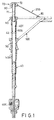
- an automatic spreading umbrella of this invention is shown to include a handle shaft (40), a hub (60), a lower runner (50), a rib assembly (80), a stretcher assembly (100), an upper runner (70), a coiled compression spring (90), and a spreader assembly (200).
- the handle shaft (40) is a known spring-loaded telescopic handle shaft that has a tubular top end portion (40T) with a distal end surface.
- a stop member (42) is disposed in the top end portion (40T) and is spaced apart from the distal end surface.
- the hub (60) is mounted securely on the top end portion (40T) of the handle shaft (40).
- the lower runner (50) is mounted slidably on the handle shaft (40) and is movable toward and away from the hub (60).
- the lower runner (50) can be locked releasably on the handle shaft (40) in a known manner so as to retain the umbrella in a folded state (see Fig.2).
- the lower runner (50) is preferably provided with a radial notch (50R).
- the handle shaft (40) is provided with a spring-biased catch (40E) at a lower portion thereof to engage the notch (50R) of the lower runner (50), thereby locking the lower runner (50) on the handle shaft (40). Operation of the catch (40E) will result in release of the lower runner (50) from the locked state.
- the rib assembly (80) is mounted pivotally at one end on the hub (60) in a conventional manner.
- a canopy (not shown) is mounted on the rib assembly (80) in a manner that is known in the art.
- the stretcher assembly (100) is connected operably to the rib assembly (80) and the lower runner (50) in a known manner.
- the upper runner (70) has an enlarged head (72) disposed above the hub (60), and a guide shaft (71) that extends from the enlarged head (72) and into the tubular top end portion (40T) of the handle shaft (40) .
- the compression spring (90) is sleeved on the guide shaft (71), and has a bottom end (90B) that is disposed in the top end portion (40T) of the handle shaft (40) and that abuts against the stop member (42), and a top end (90T) that extends outwardly of the top end portion (40T) of the handle shaft (40) and that abuts against the head (72) of the upper runner (70).
- the spreader assembly (200) is connected operably to the rib assembly (80) and the head (72) of the upper runner (70).
- the stretcher assembly (100) will pull the rib assembly (80) to the folded state, thereby causing the rib assembly (80) to pull the spreader assembly (200) and move the head (72) of the upper runner (70) toward the hub (60) and compress the compression spring (90).
- the lower runner (50) can be locked on the handle shaft (40) at this time.
- the compression spring (90) expands and pushes the upper runner (70) away from the hub (60).
- the spreader assembly (200) then pulls the rib assembly (80) to a stretched state, as best shown in Figure 1, thereby pulling the stretcher assembly (100) to move the lower runner (50) toward the hub (60).
- the stop member (42) can be a pin which extends through a radial hole formed through the top end portion (40T) of the handle shaft (40). Alternatively, the stop member (42) can be formed integrally with the top end portion (40T).
Landscapes
- Walking Sticks, Umbrellas, And Fans (AREA)
- Closed-Circuit Television Systems (AREA)
- Paper (AREA)
- Liquid Crystal (AREA)
- Operating, Guiding And Securing Of Roll- Type Closing Members (AREA)
- Accommodation For Nursing Or Treatment Tables (AREA)
Claims (1)
- Schirm folgendes aufweisend:wobei, wenn der untere Schieber (50) nach unten von der Hülse (60) fort bewegt wird, der Streckaufbau (100) den Speichenaufbau (80) in einen gefalteten Zustand zieht, wodurch die Druckfeder (90) zusammengedrückt wird, wohingegen, wenn die Druckfeder (90) expandiert und den oberen Schieber (70) nach oben von der Hülse (60) fort schiebt, der Spreizaufbau (200) den Speichenaufbau (80) in einen gestreckten Zustand zieht, wodurch der Streckaufbau (100) gezogen wird, um den unteren Schieber (50) zu der Hülse (60) zu bewegen,eine Griffstange (40) mit einem rohrförmigen oberen Endabschnitt (40T), in dem ein Stoppelement (42) angeordnet ist,eine Buchse (60), die an dem oberen Endabschnitt (40T) der Griffstange (40) fest montiert ist,einen unteren Schieber (50), der verschieblich auf der Griffstange (40) unterhalb der Buchse (60) befestigt und zu der Buchse (60) hin und von dieser fort beweglich ist,einen oberen Schieber (70), der auf der Griffstange (40) oberhalb der Buchse (60) verschieblich angeordnet ist,einen Speichenaufbau (80), der schwenkbar mit einem Ende an der Buchse (60) befestigt ist,einen Streckaufbau (100), der wirksam mit dem Speichenaufbau (80) und dem unteren Schieber (50) verbunden ist,eine gewendelte Druckfeder (90), die ein unteres Ende (90B), das an dem oberen Endabschnitt (40T) der Griffstange (40) angeordnet ist und das gegen das Stoppelement (42) anliegt, und ein oberes Ende aufweist, das an dem oberen Schieber (70) anliegt, undeinen Spreizaufbau (200), der wirksam mit dem Speichenaufbau (80) und dem oberen Schieber (70) verbunden ist,
wobei der Schirm zusätzlich folgendes aufweist:die Griffstange (40) ist mit einer federvorgespannten Sperrnase (40E) versehen, die unterhalb des unteren Schiebers (50) angeordnet ist und die radial nach innen vorgespannt ist, undder untere Schieber (50) besitzt eine Außenfläche, die mit einer Ausnehmung (50R) versehen ist, wobei der untere Schieber (50) nach unten von der Hülse (60) fort geschoben werden kann, damit die Spermase (40E) in Eingriff mit der Ausnehmung (50R) gelangt, um den unteren Schieber auf der Griffstange (40) zu verriegeln, wodurch der gefaltete Zustand des Schirms erhalten bleibt.
Priority Applications (4)
| Application Number | Priority Date | Filing Date | Title |
|---|---|---|---|
| AT98306395T ATE264074T1 (de) | 1998-08-11 | 1998-08-11 | Automatisch öffnender schirm |
| DE69823181T DE69823181T2 (de) | 1998-08-11 | 1998-08-11 | Automatisch öffnender Schirm |
| EP98306395A EP0979623B1 (de) | 1998-08-11 | 1998-08-11 | Automatisch öffnender Schirm |
| ES98306395T ES2217507T3 (es) | 1998-08-11 | 1998-08-11 | Paraguas de apertura automatica. |
Applications Claiming Priority (1)
| Application Number | Priority Date | Filing Date | Title |
|---|---|---|---|
| EP98306395A EP0979623B1 (de) | 1998-08-11 | 1998-08-11 | Automatisch öffnender Schirm |
Publications (2)
| Publication Number | Publication Date |
|---|---|
| EP0979623A1 EP0979623A1 (de) | 2000-02-16 |
| EP0979623B1 true EP0979623B1 (de) | 2004-04-14 |
Family
ID=8234999
Family Applications (1)
| Application Number | Title | Priority Date | Filing Date |
|---|---|---|---|
| EP98306395A Expired - Lifetime EP0979623B1 (de) | 1998-08-11 | 1998-08-11 | Automatisch öffnender Schirm |
Country Status (4)
| Country | Link |
|---|---|
| EP (1) | EP0979623B1 (de) |
| AT (1) | ATE264074T1 (de) |
| DE (1) | DE69823181T2 (de) |
| ES (1) | ES2217507T3 (de) |
Families Citing this family (1)
| Publication number | Priority date | Publication date | Assignee | Title |
|---|---|---|---|---|
| RU2234226C1 (ru) * | 2003-01-23 | 2004-08-20 | Макс ВАНГ | Каркас зонта |
Family Cites Families (6)
| Publication number | Priority date | Publication date | Assignee | Title |
|---|---|---|---|---|
| US4548222A (en) * | 1984-02-16 | 1985-10-22 | Day San Tong | Full-automatic umbrella |
| AU632448B2 (en) * | 1991-07-26 | 1992-12-24 | Day, Sheng-Tong | Lightly operable fully automatic umbrella |
| US5247955A (en) * | 1992-08-17 | 1993-09-28 | Wu Woh Wen | Ergonomically operating automatic umbrella |
| US5232004A (en) * | 1992-09-21 | 1993-08-03 | Wu Woh Wen | Automatic umbrella having wind-resistant buffer effect |
| US5361792A (en) * | 1994-05-03 | 1994-11-08 | Lin Chung Kuang | Reliably operated automatic umbrella with upwardly and downwardly thrusted push button |
| US5533541A (en) * | 1995-05-16 | 1996-07-09 | Cheng; Jonathan | Automatic umbrella with multiple operation modes |
-
1998
- 1998-08-11 DE DE69823181T patent/DE69823181T2/de not_active Expired - Fee Related
- 1998-08-11 ES ES98306395T patent/ES2217507T3/es not_active Expired - Lifetime
- 1998-08-11 AT AT98306395T patent/ATE264074T1/de not_active IP Right Cessation
- 1998-08-11 EP EP98306395A patent/EP0979623B1/de not_active Expired - Lifetime
Also Published As
| Publication number | Publication date |
|---|---|
| DE69823181D1 (de) | 2004-05-19 |
| EP0979623A1 (de) | 2000-02-16 |
| DE69823181T2 (de) | 2005-01-27 |
| ATE264074T1 (de) | 2004-04-15 |
| ES2217507T3 (es) | 2004-11-01 |
Similar Documents
| Publication | Publication Date | Title |
|---|---|---|
| CA2132602C (en) | Multiple-fold automatic umbrella | |
| US5224505A (en) | Automatic umbrella with upwardly and downwardly thrusted push button | |
| US5740823A (en) | Lightening safety automatic umbrella | |
| US4548222A (en) | Full-automatic umbrella | |
| EP0425071B1 (de) | Automatischer Schirm | |
| US5267583A (en) | Multiple-fold automatic umbrella controlled by single push button | |
| US6988504B1 (en) | Umbrella assembly | |
| US4421133A (en) | Umbrella | |
| US4989625A (en) | Stably-retained automatic umbrella | |
| US20020104557A1 (en) | Adjusting sleeve assembly for a sunshade with a tiltable canopy | |
| CA2047974C (en) | Lightly operable fully automatic umbrella | |
| US4936332A (en) | Simply-constructed automatic umbrella for preventing false operation | |
| US5564449A (en) | Anti-twisting automatic umbrella | |
| US5309932A (en) | Folding collapsible frame assembly for an automatic folding umbrella | |
| US5533541A (en) | Automatic umbrella with multiple operation modes | |
| EP2289363A1 (de) | Sicherheitsvorrichtung für automatisch aufklappbaren Regenschirm | |
| EP0498986B1 (de) | Automatischer Schirm mit einem in gerader Linie zu bewegenden Druckknopf zum Öffnen und Schliessen des Schirmes | |
| US5060684A (en) | Automatic umbrella foldably retained by tip cap | |
| US5247955A (en) | Ergonomically operating automatic umbrella | |
| EP0979623A1 (de) | Automatisch öffnender Schirm | |
| JP4768959B2 (ja) | 自立可能なステッキ | |
| CA2043209A1 (en) | Automatic umbrella | |
| US20030070700A1 (en) | Sunshade with telescopic ribs | |
| WO2001012009A9 (en) | Umbrella assembly | |
| JPH0767405B2 (ja) | 自動開閉傘 |
Legal Events
| Date | Code | Title | Description |
|---|---|---|---|
| PUAI | Public reference made under article 153(3) epc to a published international application that has entered the european phase |
Free format text: ORIGINAL CODE: 0009012 |
|
| AK | Designated contracting states |
Kind code of ref document: A1 Designated state(s): AT DE ES FR GB IT PT |
|
| AX | Request for extension of the european patent |
Free format text: AL;LT;LV;MK;RO;SI |
|
| 17P | Request for examination filed |
Effective date: 20000228 |
|
| AKX | Designation fees paid |
Free format text: AT DE ES FR GB IT PT |
|
| 17Q | First examination report despatched |
Effective date: 20020116 |
|
| GRAH | Despatch of communication of intention to grant a patent |
Free format text: ORIGINAL CODE: EPIDOS IGRA |
|
| GRAS | Grant fee paid |
Free format text: ORIGINAL CODE: EPIDOSNIGR3 |
|
| GRAA | (expected) grant |
Free format text: ORIGINAL CODE: 0009210 |
|
| AK | Designated contracting states |
Kind code of ref document: B1 Designated state(s): AT DE ES FR GB IT PT |
|
| PG25 | Lapsed in a contracting state [announced via postgrant information from national office to epo] |
Ref country code: IT Free format text: LAPSE BECAUSE OF FAILURE TO SUBMIT A TRANSLATION OF THE DESCRIPTION OR TO PAY THE FEE WITHIN THE PRESCRIBED TIME-LIMIT;WARNING: LAPSES OF ITALIAN PATENTS WITH EFFECTIVE DATE BEFORE 2007 MAY HAVE OCCURRED AT ANY TIME BEFORE 2007. THE CORRECT EFFECTIVE DATE MAY BE DIFFERENT FROM THE ONE RECORDED. Effective date: 20040414 Ref country code: AT Free format text: LAPSE BECAUSE OF FAILURE TO SUBMIT A TRANSLATION OF THE DESCRIPTION OR TO PAY THE FEE WITHIN THE PRESCRIBED TIME-LIMIT Effective date: 20040414 |
|
| REG | Reference to a national code |
Ref country code: GB Ref legal event code: FG4D |
|
| REF | Corresponds to: |
Ref document number: 69823181 Country of ref document: DE Date of ref document: 20040519 Kind code of ref document: P |
|
| PGFP | Annual fee paid to national office [announced via postgrant information from national office to epo] |
Ref country code: FR Payment date: 20040927 Year of fee payment: 7 |
|
| PGFP | Annual fee paid to national office [announced via postgrant information from national office to epo] |
Ref country code: ES Payment date: 20040929 Year of fee payment: 7 |
|
| REG | Reference to a national code |
Ref country code: ES Ref legal event code: FG2A Ref document number: 2217507 Country of ref document: ES Kind code of ref document: T3 |
|
| ET | Fr: translation filed | ||
| PLBE | No opposition filed within time limit |
Free format text: ORIGINAL CODE: 0009261 |
|
| STAA | Information on the status of an ep patent application or granted ep patent |
Free format text: STATUS: NO OPPOSITION FILED WITHIN TIME LIMIT |
|
| 26N | No opposition filed |
Effective date: 20050117 |
|
| PGFP | Annual fee paid to national office [announced via postgrant information from national office to epo] |
Ref country code: DE Payment date: 20050804 Year of fee payment: 8 |
|
| PGFP | Annual fee paid to national office [announced via postgrant information from national office to epo] |
Ref country code: GB Payment date: 20050810 Year of fee payment: 8 |
|
| PG25 | Lapsed in a contracting state [announced via postgrant information from national office to epo] |
Ref country code: ES Free format text: LAPSE BECAUSE OF NON-PAYMENT OF DUE FEES Effective date: 20050812 |
|
| REG | Reference to a national code |
Ref country code: ES Ref legal event code: FD2A Effective date: 20050812 |
|
| PG25 | Lapsed in a contracting state [announced via postgrant information from national office to epo] |
Ref country code: DE Free format text: LAPSE BECAUSE OF NON-PAYMENT OF DUE FEES Effective date: 20070301 |
|
| GBPC | Gb: european patent ceased through non-payment of renewal fee |
Effective date: 20060811 |
|
| PG25 | Lapsed in a contracting state [announced via postgrant information from national office to epo] |
Ref country code: GB Free format text: LAPSE BECAUSE OF NON-PAYMENT OF DUE FEES Effective date: 20060811 |
|
| PG25 | Lapsed in a contracting state [announced via postgrant information from national office to epo] |
Ref country code: PT Free format text: LAPSE BECAUSE OF NON-PAYMENT OF DUE FEES Effective date: 20040914 |
|
| PG25 | Lapsed in a contracting state [announced via postgrant information from national office to epo] |
Ref country code: FR Free format text: LAPSE BECAUSE OF NON-PAYMENT OF DUE FEES Effective date: 20050831 |
|
| REG | Reference to a national code |
Ref country code: FR Ref legal event code: ST Effective date: 20110531 |