EP0979632A2 - Suction device - Google Patents
Suction device Download PDFInfo
- Publication number
- EP0979632A2 EP0979632A2 EP99111838A EP99111838A EP0979632A2 EP 0979632 A2 EP0979632 A2 EP 0979632A2 EP 99111838 A EP99111838 A EP 99111838A EP 99111838 A EP99111838 A EP 99111838A EP 0979632 A2 EP0979632 A2 EP 0979632A2
- Authority
- EP
- European Patent Office
- Prior art keywords
- opening
- suction device
- connection opening
- air
- suction
- Prior art date
- Legal status (The legal status is an assumption and is not a legal conclusion. Google has not performed a legal analysis and makes no representation as to the accuracy of the status listed.)
- Withdrawn
Links
Images


Classifications
-
- A—HUMAN NECESSITIES
- A47—FURNITURE; DOMESTIC ARTICLES OR APPLIANCES; COFFEE MILLS; SPICE MILLS; SUCTION CLEANERS IN GENERAL
- A47L—DOMESTIC WASHING OR CLEANING; SUCTION CLEANERS IN GENERAL
- A47L5/00—Structural features of suction cleaners
- A47L5/12—Structural features of suction cleaners with power-driven air-pumps or air-compressors, e.g. driven by motor vehicle engine vacuum
- A47L5/22—Structural features of suction cleaners with power-driven air-pumps or air-compressors, e.g. driven by motor vehicle engine vacuum with rotary fans
- A47L5/28—Suction cleaners with handles and nozzles fixed on the casings, e.g. wheeled suction cleaners with steering handle
- A47L5/32—Suction cleaners with handles and nozzles fixed on the casings, e.g. wheeled suction cleaners with steering handle with means for connecting a hose
-
- A—HUMAN NECESSITIES
- A47—FURNITURE; DOMESTIC ARTICLES OR APPLIANCES; COFFEE MILLS; SPICE MILLS; SUCTION CLEANERS IN GENERAL
- A47L—DOMESTIC WASHING OR CLEANING; SUCTION CLEANERS IN GENERAL
- A47L5/00—Structural features of suction cleaners
- A47L5/12—Structural features of suction cleaners with power-driven air-pumps or air-compressors, e.g. driven by motor vehicle engine vacuum
- A47L5/22—Structural features of suction cleaners with power-driven air-pumps or air-compressors, e.g. driven by motor vehicle engine vacuum with rotary fans
- A47L5/36—Suction cleaners with hose between nozzle and casing; Suction cleaners for fixing on staircases; Suction cleaners for carrying on the back
-
- A—HUMAN NECESSITIES
- A47—FURNITURE; DOMESTIC ARTICLES OR APPLIANCES; COFFEE MILLS; SPICE MILLS; SUCTION CLEANERS IN GENERAL
- A47L—DOMESTIC WASHING OR CLEANING; SUCTION CLEANERS IN GENERAL
- A47L9/00—Details or accessories of suction cleaners, e.g. mechanical means for controlling the suction or for effecting pulsating action; Storing devices specially adapted to suction cleaners or parts thereof; Carrying-vehicles specially adapted for suction cleaners
- A47L9/22—Mountings for motor fan assemblies
Definitions
- the invention relates to a suction device for sucking Containing dirt or the like and air as a carrier medium Suction material, for example dust air, with a suction flow generating blower, the dirt or in the suction device The like. Separated and the dirt or the like freed Clean air through a flow channel to a blow-out opening is led to the clean air into the environment is blown out.
- a suction device for sucking Containing dirt or the like and air as a carrier medium Suction material, for example dust air
- a suction flow generating blower the dirt or in the suction device The like.
- Such suction devices are used, for example, in connection with one that creates dust when machining a workpiece Handheld power tool that uses a Hose line is connected to the suction device, so that the dust generated during workpiece machining is extracted and collected in a dirty space of the suction device becomes.
- the invention relates not only to suction devices for dry suction material such as dust air, but also on Suction devices for wet operation, in particular polluted water is sucked in.
- suction devices are regularly portable and / or movable educated.
- the clean air enters the device at the outlet opening the environment. This creates air movements in the Environment that should be kept as weak as possible, to whirl up dust or other light things to avoid in the area. Therefore one uses large areas Blow out openings so that the clean air with accordingly at a low speed.
- the large-area discharge opening one to be attached to the outside of the device housing Assigned adapter piece in which the flow cross section from the surface of the discharge opening to a connection opening is reduced to which the air hose is connected can be.
- This adapter piece are both Operating modes possible, that is, you can use the clean air with the adapter removed, directly into the environment or with the adapter piece attached through the air hose head elsewhere.
- the assembly and disassembly of the adapter piece is cumbersome. In addition, it brings significant production costs with yourself. Furthermore, the adapter piece, you worked with the operating mode "blow-out opening" and you want to switch to the "clean air removal by means of an air hose ", be laid so that it must first be searched.
- the present invention is therefore based on the object a suction device of the type mentioned create a change in mode, in particular in terms of handling, simple way is possible.
- the Flow channel contains a branch at which on the one hand a passage opening for the passage of the Clean air to the blow-out opening and on the other hand a connection opening arranged for connecting an air hose are, with a switchable from outside is present, which is between a connection opening closing and the passage opening releasing first position and one of the connection opening releasing and closing the passage opening second position is adjustable.
- connection opening for inserting the air hose is formed and the changeover device through the air hose can be actuated.
- the changeover device cannot be operated separately. Just by plugging it in of the air hose is adjusted from their first to the second position. Takes if you remove the air hose, the changeover device adjusts back again.
- the suction device 1 shown in the drawing is used for Sucking in dirt or the like and air as a carrier medium containing suction material, for example dust air.
- the Dirt or the like is inside the suction device 1 from the Separated carrier air, after which the dirt or the like. clean air is led outside.
- the general structure of the suction device 1 is as follows:
- the suction device has a connecting piece 2 for connection a hose line, not shown, through which the suction material is sucked in.
- the other end of the Hose line is for example with a hand machine tool like grinder, saw or milling machine connected, in their operation when the respective workpiece is machined dust accumulates. Instead of a hand machine tool can of course also be connected to another device become.
- the suction device 1 can not only for dry suction material, but also used for wet suction material become.
- the suction device 1 also has a Device units containing device upper part 3 and one Lower part 4 of the device, which contains a dirt space 5.
- the equipment units are essentially one Filter device 6, one generating the suction flow Fan 7 and a motor driving the fan are formed.
- the fan 7 is arranged on the suction side and is located seen behind the Filter device 6.
- Filter device 6 arranged above the dirt space 4. That sucked in, through the connecting piece 2 arriving suction material passes through a connecting pipe 8, which is a boundary wall 9 of the Dirt space 5 passes through, in the top area of the dirt chamber 5, after which the filter device 6 Dirt particles are separated from themselves and themselves accumulate below in the dirt space 5 while the dirt or the like. Clean air released by the filter device 6 flows to the blower 7 and from there to the outside.
- the upper part of the device can be used for cleaning purposes in particular 3 lifted off the lower part of the device, for example by one Joint axis 10 are pivoted up.
- the suction device 1 is portable and portable or movable. For this purpose, it has casters 11.
- suction device is only an example. In connection with the present invention it could also be different.
- the device housing 12 contains a flow channel 13 for the clean air, which in the embodiment consists of three Channel sections 14, 15, 16 is composed. It extends the duct section 14 extends from the fan 7 arranged at the top in the area of a device outside 17 down in the floor area of the device, where the suction device through to the opposite outside of the device 18 Channel section 15 connects to the other outside of the device 18 the one going up again Channel section 16 follows. This channel course can also in individual be different.
- the flow channel 13 leads to a blow-out opening 19, those in the embodiment of two at a distance from each other arranged individual openings is formed each composed of a number of louvers.
- a blow-out opening 19 is designed in detail is, that is, whether it is divided into individual openings and / or is composed of louvers of no further importance. It is only important that they have one so large blow-out cross section - this corresponds to the embodiment the sum of the louvre areas - that the clean air reaching the blow-out opening 19 at the blow-out opening 19 with the lowest possible Speed escapes into the environment so that in the No disturbing air currents and whirling around of dust or other things.
- the outlet opening 19 in the form of the louvers is in the outside of the device 18 included along the Channel section 16 extends.
- the blow-out opening 19 is located itself in the outside channel wall of the channel section 16.
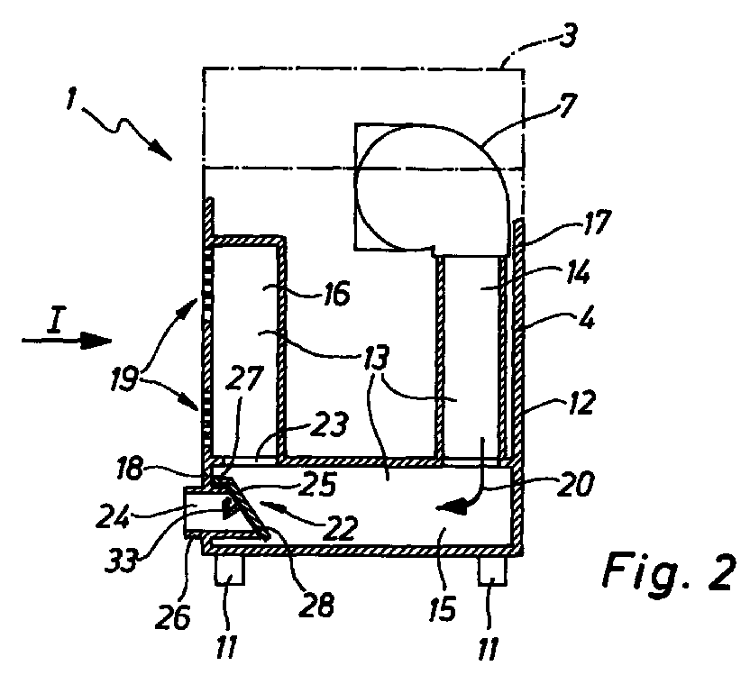
- the flow channel 13 contains, in the exemplary embodiment the channel section 15, a branch point 22, on the one hand a passage opening 23 for the Passage of the clean air to the blow-out opening 19 and on the other hand a connection opening 24 for connecting the air hose 21 are arranged.
- a changeover device 25 available, which can be operated from the outside and between a first position (Fig. 2 and 3) and a second position (Fig. 4) is adjustable. In the first Position, the changeover device 25 closes the connection opening 24 and opens the passage opening 23, while in the second position the passage opening 23 open and the connection opening 24 is closed.
- connection opening 24 is located on the outside of the device, so that the air hose 21 without difficulty from can be connected from the outside.
- the connection opening 24 below the blow-out opening 19 arranged on the same outside of the device 18.
- connection opening 24 is in the embodiment of a connecting piece 26 is formed, which extends into the Flow channel 13 - channel section 15 - extends into it.
- connection opening 24 is expediently designed in such a way that that the air hose 21 can be inserted, at the end of this a suitable end piece is attached can be. If here from plugging in the air hose is spoken, so screwing in or any other introduction can be detected.
- the arrangement is also such that that the switching device 25 when inserting the Air hose 21 is actuated by this.
- the changeover device is located 25 in its first, the connection opening 24 closing position. If you plug in the air hose 21, he pushes against the changeover device 25 and transfers it into the second position, in which it is the connection opening 24 releases and the passage opening 23 closes (see Fig. 4). This lifting of the changeover device 25 from the connection opening 24 takes place against a restoring force, so that the changeover 25 at Removing the air hose 21 automatically in their first position moved.
- this restoring force can the weight of the switching device 25, the that is, the changeover device 25 normally takes if the air hose 21 is missing under the action of gravity their first position.
- the restoring force could also be a spring force (not shown).
- the details of this link are more common Design, so that there is a representation in detail superfluous.
- the closure flap 28 is facing each other Mouths of the connection opening 24 and the passage opening 23 assigned, which is in the swivel path (Double arrow 29) of the flap 28 are.
- the passage opening 23 is located in a wall section 30 of the device housing, so that the shutter 28 in its second position around the passage opening 23 around against this wall section 30.
- the inner mouth of the connection opening 24, that is at Embodiment the inner end face of the connecting piece 26, where the connection opening 24 in the flow channel 13 opens out, is located in an outlet level 31, the suction device in its position of use 1 so inclined that their normal direction 32 obliquely points upwards.
- the connection opening 24 is closed to the blow-out opening 19 flowing clean air on the opposite of the connection opening 24 Side of the flap 28 hits and these are thus even firmer against the mouth of the connection opening presses.
- connection opening 24 and the passage opening 23 are with their axial directions in the embodiment in aligned substantially at right angles to each other.
- connection opening 24 on the front side of the Channel section 15, while the passage opening 23 at Transition of the channel section 15 to the channel section 16 is arranged is.
- connection opening 24 runs essentially horizontally, and the passage opening 23 is above the Connection opening 24 arranged.
- the air hose 21 abuts its insertion into the connection opening 24 is not immediate against the flap 28 but against one Actuator 33, which at the port 24th facing side of the flap 28 is arranged and, the shutter 28 is in its first Position, protrudes into the connection opening 24.
- the Arrangement further made such that the actuator 33rd when pivoting the flap 28 into the second Position slipped onto the outside of the air hose jacket, as can be seen from Fig. 4.
- the inside of the Connection opening 24 projecting end of the air hose 21 then presses the one that rests on the hose jacket Actuator and about this the flap 28th against the passage opening 23.
- the actuator 33 is expediently designed to be resilient, so that the flap 28 elastically against the passage opening 23 is held.
- the Actuator 33 a protruding from the closure flap 28, elastically bendable holding arm 34, from which the lot 35 protrudes against which the air hose his plugging.
- the flap 28 is made of plastic, which Actuator 33 is integrally formed.
- changeover device not essentially from a closure flap must be formed, but also a slide or can have another part as a closure member.
Landscapes
- Engineering & Computer Science (AREA)
- Mechanical Engineering (AREA)
- Cleaning In General (AREA)
- Manipulator (AREA)
- Branching, Merging, And Special Transfer Between Conveyors (AREA)
- Massaging Devices (AREA)
- Nozzles For Electric Vacuum Cleaners (AREA)
Abstract
Ein Sauggerät (1) zum Ansaugen von Schmutz oder dgl. und Luft
als Trägermedium enthaltendem Sauggut, beispielsweise Staubluft
weist ein den Saugstrom erzeugendes Gebläse (7) auf. Der
Schmutz oder dgl. wird im Sauggerät (1) abgesondert, und die
vom Schmutz oder dgl. befreite Reinluft wird durch einen
Strömungskanal (13) zu einer Ausblasöffnung (19) geführt, an
der die Reinluft in die Umgebung ausgeblasen wird. Der Strömungskanal
(13) enthält eine Verzweigungsstelle (22), an der
einerseits eine Durchtrittsöffnung (23) für den Durchtritt
der Reinluft zur Ausblasöffnung (19) und andererseits eine
Anschlußöffnung (24) zum Anschließen eines Luftschlauches angeordnet
sind. Eine von außen her betätigbare Umstelleinrichtung
(25) ist zwischen einer die Anschlußöffnung (24) verschließenden
und die Durchtrittsöffnung (23) freigebenden ersten
Stellung und einer die Anschlußöffnung (24) freigebenden
und die Durchtrittsöffnung (23) verschließenden zweiten Stellung
verstellbar.
Description
Die Erfindung betrifft ein Sauggerät zum Ansaugen von Schmutz oder dgl. und Luft als Trägermedium enthaltendem Sauggut, beispielsweise Staubluft, mit einem den Saugstrom erzeugenden Gebläse, wobei im Sauggerät der Schmutz oder dgl. abgesondert und die vom Schmutz oder dgl. befreite Reinluft durch einen Strömungskanal zu einer Ausblasöffnung geführt wird, an der die Reinluft in die Umgebung ausgeblasen wird.The invention relates to a suction device for sucking Containing dirt or the like and air as a carrier medium Suction material, for example dust air, with a suction flow generating blower, the dirt or in the suction device The like. Separated and the dirt or the like freed Clean air through a flow channel to a blow-out opening is led to the clean air into the environment is blown out.
Solche Sauggeräte werden beispielsweise in Zusammenhang mit einer beim Bearbeiten eines Werkstücks Staub erzeugenden Handwerkzeugmaschine verwendet, die über eine Schlauchleitung mit dem Sauggerät verbunden wird, so daß der bei der Werkstückbearbeitung anfallende Staub abgesaugt und in einem Schmutzraum des Sauggerätes gesammelt wird.Such suction devices are used, for example, in connection with one that creates dust when machining a workpiece Handheld power tool that uses a Hose line is connected to the suction device, so that the dust generated during workpiece machining is extracted and collected in a dirty space of the suction device becomes.
Die Erfindung bezieht sich jedoch nicht nur auf Sauggeräte für trockenes Sauggut wie Staubluft, sondern auch auf Sauggeräte für den Naßbetrieb, bei denen insbesondere verschmutztes Wasser angesaugt wird.However, the invention relates not only to suction devices for dry suction material such as dust air, but also on Suction devices for wet operation, in particular polluted water is sucked in.
Solche Sauggeräte sind regelmäßig tragbar und/oder verfahrbar ausgebildet.Such suction devices are regularly portable and / or movable educated.
Die Reinluft tritt an der Ausblasöffnung aus dem Gerät in die Umgebung. Hierdurch entstehen Luftbewegungen in der Umgebung, die möglichst schwach gehalten werden sollten, um das Aufwirbeln von Staub oder sonstigen leichten Dingen in der Umgebung zu vermeiden. Daher verwendet man großflächige Ausblasöffnungen, so daß die Reinluft mit entsprechend kleiner Geschwindigkeit austritt.The clean air enters the device at the outlet opening the environment. This creates air movements in the Environment that should be kept as weak as possible, to whirl up dust or other light things to avoid in the area. Therefore one uses large areas Blow out openings so that the clean air with accordingly at a low speed.
Es gibt Anwendungsfälle, bei denen das Ausblasen der Reinluft in die Umgebung unerwünscht ist. In solchen Fällen wird die Reinluft durch einen Luftschlauch zu einer anderen Stelle geleitet, an der sie nicht weiter stört.There are applications in which the clean air is blown out in the environment is undesirable. In such cases the clean air is changed to another through an air hose Point where it does not bother you.
Bei einem bekannten Sauggerät ist der großflächigen Ausblasöffnung ein außen am Gerätegehäuse zu befestigendes Adapterstück zugeordnet, in dem der Strömungsquerschnitt von der Fläche der Ausblasöffnung auf eine Anschlußöffnung reduziert wird, an die der Luftschlauch angeschlossen werden kann. Mit Hilfe dieses Adapterstücks sind beide Betriebsarten möglich, das heißt, man kann die Reinluft bei entferntem Adapterstück unmittelbar in die Umgebung oder bei angebrachtem Adapterstück durch den Luftschlauch woanders hin leiten.In a known suction device, the large-area discharge opening one to be attached to the outside of the device housing Assigned adapter piece in which the flow cross section from the surface of the discharge opening to a connection opening is reduced to which the air hose is connected can be. With the help of this adapter piece are both Operating modes possible, that is, you can use the clean air with the adapter removed, directly into the environment or with the adapter piece attached through the air hose head elsewhere.
Das Montieren und Abmontieren des Adapterstücks ist umständlich. Außerdem bringt es nicht unerhebliche Gestehungskosten mit sich. Des weiteren kann das Adapterstück, hat man mit der Betriebsart "Ausblasöffnung" gearbeitet und will man auf die Betriebsart "Reinluftabfuhr mittels Luftschlauch" übergehen, verlegt sein, so daß es erst gesucht werden muß.The assembly and disassembly of the adapter piece is cumbersome. In addition, it brings significant production costs with yourself. Furthermore, the adapter piece, you worked with the operating mode "blow-out opening" and you want to switch to the "clean air removal by means of an air hose ", be laid so that it must first be searched.
Der vorliegenden Erfindung liegt daher die Aufgabe zugrunde, ein Sauggerät der eingangs genannten Art zu schaffen, bei dem ein Wechsel der Betriebsart in, insbesondere was die Handhabung anbelangt, einfacher Weise möglich ist.The present invention is therefore based on the object a suction device of the type mentioned create a change in mode, in particular in terms of handling, simple way is possible.
Diese Aufgabe wird erfindungsgemäß dadurch gelöst, daß der Strömungskanal eine Verzweigungsstelle enthält, an der einerseits eine Durchtrittsöffnung für den Durchtritt der Reinluft zur Ausblasöffnung und andererseits eine Anschlußöffnung zum Anschließen eines Luftschlauches angeordnet sind, wobei eine von außen her betätigbare Umstelleinrichtung vorhanden ist, die zwischen einer die Anschlußöffnung verschließenden und die Durchtrittsöffnung freigebenden ersten Stellung und einer die Anschlußöffnung freigebenden und die Durchtrittsöffnung verschließenden zweiten Stellung verstellbar ist.This object is achieved in that the Flow channel contains a branch at which on the one hand a passage opening for the passage of the Clean air to the blow-out opening and on the other hand a connection opening arranged for connecting an air hose are, with a switchable from outside is present, which is between a connection opening closing and the passage opening releasing first position and one of the connection opening releasing and closing the passage opening second position is adjustable.
Somit sind an dem Gerät getrennt voneinander sowohl eine Ausblasöffnung als auch eine Anschlußöffnung für einen Luftschlauch vorhanden, die wahlweise verwendet werden können. Hierzu muß lediglich die Umstelleinrichtung betätigt werden, so daß die Reinluft im Geräte-Inneren entweder zur Ausblasöffnung oder zur Anschlußöffnung gelangt. Zum Umstellen sind keinerlei Montagearbeiten erforderlich.This means that both are separated on the device Blow-out opening as well as a connection opening for one Air hose available, which can be used optionally can. To do this, the changeover device only has to be actuated be so that the clean air inside the device either reaches the blow-out opening or the connection opening. No assembly work is required to change over.
Bei einer bevorzugten Ausführungsform ist vorgesehen, daß die Anschlußöffnung zum Einstecken des Luftschlauchs ausgebildet und die Umstelleinrichtung durch den Luftschlauch betätigbar ist. In diesem Falle muß die Umstelleinrichtung nicht gesondert betätigt werden. Allein durch das Einstecken des Luftschlauchs verstellt sich die Umstelleinrichtung aus ihrer ersten in die zweite Stellung. Nimmt man den Luftschlauch weg, verstellt sich die Umstelleinrichtung wieder zurück.In a preferred embodiment it is provided that the connection opening for inserting the air hose is formed and the changeover device through the air hose can be actuated. In this case, the changeover device cannot be operated separately. Just by plugging it in of the air hose is adjusted from their first to the second position. Takes if you remove the air hose, the changeover device adjusts back again.
Weitere zweckmäßige Ausgestaltungen der Erfindung sind in den Unteransprüchen angegeben.Further expedient embodiments of the invention are in specified in the subclaims.
Ein Ausführungsbeispiel der Erfindung wird nun anhand der Zeichnung erläutert. Es zeigen:
- Fig. 1
- ein erfindungsgemäßes Sauggerät in schematischer Seitenansicht gemäß Pfeil I in Fig. 2,
- Fig. 2
- das Sauggerät nach Fig. 1 im Schnitt gemäß der Schnittlinie II-II, wobei der Umriß im oberen Bereich nur strichpunktiert angedeutet ist, in stark schematisierter Wiedergabe,
- Fig. 3
- einen die Verzweigungsstelle enthaltenden Ausschnitt aus Fig. 2 in vergrößerter Darstellung, wobei sich die Umstelleinrichtung wie in Fig. 2 in ihrer ersten Stellung befindet, in der sie die Anschlußöffnung verschließt, und
- Fig. 4
- die Anordnung nach Fig. 3 bei durch die Anschlußöffnung eingestecktem Luftschlauch, so daß die Umstelleinrichtung ihre zweite Stellung einnimmt, in der die Durchtrittsöffnung zur Ausblasöffnung verschlossen ist.
- Fig. 1
- an inventive suction device in a schematic side view according to arrow I in Fig. 2,
- Fig. 2
- 1 in section along the section line II-II, the outline in the upper area being indicated only by dash-dotted lines, in a highly schematic representation,
- Fig. 3
- 2 in an enlarged representation, the switching device being in its first position, as in FIG. 2, in which it closes the connection opening, and
- Fig. 4
- 3 with the air hose inserted through the connection opening, so that the changeover device assumes its second position, in which the passage opening to the blow-out opening is closed.
Das aus der Zeichnung hervorgehende Sauggerät 1 dient zum Ansaugen von Schmutz oder dgl. und Luft als Trägermedium enthaltendem Sauggut, beispielsweise Staubluft. Der Schmutz oder dgl. wird innerhalb des Sauggerätes 1 von der Trägerluft abgesondert, wonach die vom Schmutz oder dgl. befreite Reinluft nach außen geführt wird. The suction device 1 shown in the drawing is used for Sucking in dirt or the like and air as a carrier medium containing suction material, for example dust air. The Dirt or the like is inside the suction device 1 from the Separated carrier air, after which the dirt or the like. clean air is led outside.
Der allgemeine Aufbau des Sauggerätes 1 ist folgender:The general structure of the suction device 1 is as follows:
Das Sauggerät weist einen Verbindungsstutzen 2 zum Anschließen
einer nicht dargestellten Schlauchleitung auf,
durch die das Sauggut angesaugt wird. Das andere Ende der
Schlauchleitung ist beispielsweise mit einer Handwerkzeugmaschine
wie Schleifgerät, Säge oder Fräsgerät verbunden,
bei deren Betrieb, wenn das jeweilige Werkstück bearbeitet
wird, Staub anfällt. Anstelle einer Handwerkzeugmaschine
kann selbstverständlich auch ein anderes Gerät angeschlossen
werden. Ferner kann das Sauggerät 1 nicht nur für
trockenes Sauggut, sondern auch für nasses Sauggut verwendet
werden. Das Sauggerät 1 weist ferner ein die
Geräteaggregate enthaltendes Geräte-Oberteil 3 und ein
Geräte-Unterteil 4 auf, das einen Schmutzraum 5 enthält.
Die Geräteaggregate werden im wesentlichen von einer
Filtereinrichtung 6, einem den Saugstrom erzeugenden
Gebläse 7 und einem das Gebläse antreibenden Motor gebildet.
Das Gebläse 7 ist saugseitig angeordnet und befindet
sich in Strömungsrichtung gesehen hinter der
Filtereinrichtung 6. Dabei ist die Filtereinrichtung 6
über dem Schmutzraum 4 angeordnet. Das angesaugte, durch
den Verbindungsstutzen 2 ankommende Sauggut gelangt durch
ein Verbindungsrohr 8, das eine Begrenzungswand 9 des
Schmutzraums 5 durchgreift, in den oberseitigen Bereich
des Schmutzraums 5, wonach an der Filtereinrichtung 6 die
Schmutzpartikel aus dem Sauggut abgetrennt werden und sich
unten im Schmutzraum 5 ansammeln, während die vom Schmutz
oder dgl. befreite Reinluft durch die Filtereinrichtung 6
zum Gebläse 7 strömt und von dort nach außen gelangt.The suction device has a connecting piece 2 for connection
a hose line, not shown,
through which the suction material is sucked in. The other end of the
Hose line is for example with a hand machine tool
like grinder, saw or milling machine connected,
in their operation when the respective workpiece is machined
dust accumulates. Instead of a hand machine tool
can of course also be connected to another device
become. Furthermore, the suction device 1 can not only for
dry suction material, but also used for wet suction material
become. The suction device 1 also has a
Device units containing device
Insbesondere zu Reinigungszwecken kann das Geräte-Oberteil
3 vom Geräte-Unterteil abgehoben, zum Beispiel um eine
Gelenkachse 10 hochgeschwenkt werden.The upper part of the device can be used for cleaning purposes in particular
3 lifted off the lower part of the device, for example by one
Das Sauggerät 1 ist transportabel und von Hand tragbar
oder verfahrbar. Hierzu weist es Fahrrollen 11 auf.The suction device 1 is portable and portable
or movable. For this purpose, it has
Der geschilderte Aufbau des Sauggerätes ist nur beispielhaft. In Zusammenhang mit der vorliegenden Erfindung könnte er auch anders sein.The described construction of the suction device is only an example. In connection with the present invention it could also be different.
Wesentlich ist dagegen die Art und Weise, wie die Reinluft nach außen gelangt und abgeführt wird.What is essential, however, is the way in which the clean air gets outside and is discharged.
Das Gerätegehäuse 12 enthält einen Strömungskanal 13 für
die Reinluft, der sich beim Ausführungsbeispiel aus drei
Kanalabschnitten 14, 15, 16 zusammensetzt. Dabei erstreckt
sich der Kanalabschnitt 14 vom oben angeordneten Gebläse 7
im Bereich der einen Geräte-Außenseite 17 nach unten in
den Bodenbereich des Gerätes, wo sich der das Sauggerät
bis zur entgegengesetzten Geräte-Außenseite 18 durchquerende
Kanalabschnitt 15 anschließt, auf den an der
anderen Geräte-Außenseite 18 der wieder nach oben gehende
Kanalabschnitt 16 folgt. Auch dieser Kanalverlauf kann im
einzelnen anders sein.The
Der Strömungskanal 13 führt zu einer Ausblasöffnung 19,
die beim Ausführungsbeispiel von zwei mit Abstand zueinander
angeordneten Einzelöffnungen gebildet wird, die sich
jeweils aus einer Anzahl von Luftschlitzen zusammensetzen.
In welcher Weise die Ausblasöffnung 19 im einzelnen ausgebildet
ist, das heißt, ob sie in Einzelöffnungen unterteilt
und/oder aus Luftschlitzen zusammengesetzt ist, ist
nicht weiter von Bedeutung. Wichtig ist nur, daß sie einen
so großen Ausblasquerschnitt - dieser entspricht beim Ausführungsbeispiel
der Summe der Luftschlitzflächen - aufweist,
daß die zur Ausblasöffnung 19 gelangende Reinluft
an der Ausblasöffnung 19 mit einer möglichst niedrigen
Geschwindigkeit in die Umgebung austritt, damit in der
Umgebung keine störenden Luftströmungen und Aufwirbelungen
von Staub oder sonstigen Dingen auftreten.The
Die Ausblasöffnung 19 in Gestalt der Luftschlitze ist in
der Geräte-Außenseite 18 enthalten, der entlang sich der
Kanalabschnitt 16 erstreckt. Die Ausblasöffnung 19 befindet
sich also in der außenseitigen Kanalwand des Kanalabschnitts
16. The
Die vom Gebläse 7 her in Richtung des Pfeils 20 kommende
Reinluft kann also durch die Ausblasöffnung 19 in die unmittelbare
Umgebung des Sauggerätes 1 austreten. Es ist
jedoch möglich, die Reinluft anstelle durch die Ausblasöffnung
19 in die Umgebung mittels eines Luftschlauchs 21
zu einem abseits, beispielsweise stationär angeordneten
Ort zu bringen und dort ausströmen zu lassen.The one coming from the
Hierzu enthält der Strömungskanal 13, beim Ausführungsbeispiel
der Kanalabschnitt 15, eine Verzweigungsstelle
22, an der einerseits eine Durchtrittsöffnung 23 für den
Durchtritt der Reinluft zur Ausblasöffnung 19 und andererseits
eine Anschlußöffnung 24 zum Anschließen des Luftschlauches
21 angeordnet sind. Ferner ist eine Umstelleinrichtung
25 vorhanden, die von außen her betätigbar und
zwischen einer ersten Stellung (Fig. 2 und 3) und einer
zweiten Stellung (Fig. 4) verstellbar ist. In der ersten
Stellung verschließt die Umstelleinrichtung 25 die Anschlußöffnung
24 und gibt die Durchtrittsöffnung 23 frei,
während in der zweiten Stellung die Durchtrittsöffnung 23
offen und die Anschlußöffnung 24 verschlossen ist.For this purpose, the
Auf diese Weise kann die Reinluft entweder durch die
Durchtrittsöffnung 23 zur Ausblasöffnung 19 oder durch die
Anschlußöffnung 24 in den bei dieser Betriebsart an das
Sauggerät angeschlossenen Luftschlauch 21 geleitet werden. In this way, the clean air can either through the
Die Anschlußöffnung 24 befindet sich an der Geräte-Außenseite,
so daß der Luftschlauch 21 ohne Schwierigkeiten von
außen her angeschlossen werden kann. Beim Ausführungsbeispiel
ist die Anschlußöffnung 24 unterhalb der Ausblasöffnung
19 an der gleichen Geräte-Außenseite 18 angeordnet.The
Die Anschlußöffnung 24 wird beim Ausführungsbeispiel von
einem Anschlußstutzen 26 gebildet, der sich bis in den
Strömungskanal 13 - Kanalabschnitt 15 - hinein erstreckt.The
Zweckmäßigerweise ist die Anschlußöffnung 24 so ausgebildet,
daß der Luftschlauch 21 eingesteckt werden kann,
an dessen Ende hierzu ein geeignetes Endstück angebracht
sein kann. Wenn hier von einem Einstecken des Luftschlauches
gesprochen wird, so soll damit auch ein Einschrauben oder
ein sonstiges Einführen erfaßt werden.The
Die Anordnung ist in diesem Zusammenhang ferner so getroffen,
daß die Umstelleinrichtung 25 beim Einstecken des
Luftschlauches 21 von diesem betätigt wird.In this context, the arrangement is also such that
that the switching
Ist der Luftschlauch 21 entfernt, befindet sich die Umstelleinrichtung
25 in ihrer ersten, die Anschlußöffnung
24 verschließenden Stellung. Steckt man den Luftschlauch
21 ein, stößt er gegen die Umstelleinrichtung 25 und überführt
sie in die zweite Stellung, in der sie die Anschlußöffnung
24 freigibt und die Durchtrittsöffnung 23 schließt
(siehe Fig. 4). Dieses Abheben der Umstelleinrichtung 25
von der Anschlußöffnung 24 erfolgt entgegen einer Rückstellkraft,
so daß sich die Umstelleinrichtung 25 beim
Entfernen des Luftschlauches 21 selbsttätig wieder in ihre
erste Stellung bewegt.If the
Diese Rückstellkraft kann, wie beim Ausführungsbeispiel,
die Gewichtskraft der Umstelleinrichtung 25 sein, das
heißt, die Umstelleinrichtung 25 nimmt normalerweise, wenn
der Luftschlauch 21 fehlt, unter der Wirkung der Schwerkraft
ihre erste Stellung ein.As in the exemplary embodiment, this restoring force can
the weight of the
Die Rückstellkraft könnte jedoch auch eine Federkraft sein (nicht dargestellt).However, the restoring force could also be a spring force (not shown).
Eine besonders einfache Umstelleinrichtung wird dadurch
gebildet, daß sie eine Verschlußklappe 28 aufweist, die
über eine Schwenkachse 27 am Gehäuse des Sauggerätes 1
angelenkt ist. Die Einzelheiten dieser Anlenkung sind üblicher
Bauart, so daß sich eine Darstellung im einzelnen
erübrigt. Die Verschlußklappe 28 ist den einander zugewandten
Mündungen der Anschlußöffnung 24 und der Durchtrittsöffnung
23 zugeordnet, die sich im Schwenkweg
(Doppelpfeil 29) der Verschlußklappe 28 befinden. This makes a particularly simple changeover device
formed that it has a
Die Durchtrittsöffnung 23 befindet sich in einer Wandpartie
30 des Gerätegehäuses, so daß sich die Verschlußklappe
28 in ihrer zweiten Stellung um die Durchtrittsöffnung
23 herum gegen diese Wandpartie 30 legt.The
Die innere Mündung der Anschlußöffnung 24, das heißt beim
Ausführungsbeispiel die innere Stirnseite des Anschlußstutzens
26, wo die Anschlußöffnung 24 in den Strömungskanal
13 mündet, befindet sich in einer Mündungsebene 31,
die bei in seiner Gebrauchslage befindlichem Sauggerät 1
so schräg verläuft, daß ihre Normalenrichtung 32 schräg
nach oben weist. Ferner befindet sich die Durchtrittsöffnung
23 oberhalb der Mündung der Anschlußöffnung 24, so
daß sich die Verschlußklappe 28 im Zwischenraum zwischen
der Mündung der Anschlußöffnung 24 und der Durchtrittsöffnung
23 befindet. Auf Grund der Neigung der Mündungsebene
31 lastet die an geeigneter Stelle am Gerätegehäuse
angelenkte Verschlußklappe 28 unter ihrem Eigengewicht auf
der Mündung der Anschlußöffnung 24, so daß sich eine ausreichend
dichte Anlage ergibt. Dabei kommt hinzu, daß die
bei verschlossener Anschlußöffnung 24 zur Ausblasöffnung
19 strömende Reinluft auf die der Anschlußöffnung 24 entgegengesetzte
Seite der Verschlußklappe 28 trifft und
diese somit noch fester gegen die Mündung der Anschlußöffnung
drückt. The inner mouth of the
Die Anschlußöffnung 24 und die Durchtrittsöffnung 23 sind
mit ihren axialen Richtungen beim Ausführungsbeispiel im
wesentlichen rechtwinkelig zueinander ausgerichtet. Dabei
befindet sich die Anschlußöffnung 24 an der Stirnseite des
Kanalabschnitts 15, während die Durchtrittsöffnung 23 am
Übergang des Kanalabschnitts 15 zum Kanalabschnitt 16 angeordnet
ist. In der Gebrauchslage des Sauggerätes
verläuft die Anschlußöffnung 24 im wesentlichen horizontal,
und die Durchtrittsöffnung 23 ist oberhalb der
Anschlußöffnung 24 angeordnet.The
Beim Ausführungsbeispiel stößt der Luftschlauch 21 bei
seinem Einstecken in die Anschlußöffnung 24 nicht unmittelbar
gegen die Verschlußklappe 28 sondern gegen ein
Betätigungsglied 33, das an der der Anschlußöffnung 24
zugewandten Seite der Verschlußklappe 28 angeordnet ist
und, befindet sich die Verschlußklappe 28 in ihrer ersten
Stellung, in die Anschlußöffnung 24 ragt. Dabei ist die
Anordnung ferner so getroffen, daß das Betätigungsglied 33
beim Verschwenken der Verschlußklappe 28 in die zweite
Stellung auf die Außenseite des Luftschlauchmantels aufgleitet,
wie aus Fig. 4 ersichtlich ist. Das innen aus der
Anschlußöffnung 24 ragende Ende des Luftschlauches 21
drückt dann das sich auf dem Schlauchmantel abstützende
Betätigungsglied und über dieses die Verschlußklappe 28
gegen die Durchtrittsöffnung 23. In the exemplary embodiment, the
Das Betätigungsglied 33 ist zweckmäßigerweise federnd ausgebildet,
so daß die Verschlußklappe 28 elastisch gegen
die Durchtrittsöffnung 23 gehalten wird. Hierzu weist das
Betätigungsglied 33 einen von der Verschlußklappe 28 abstehenden,
elastisch verbiegbaren Haltearm 34 auf, von dem
die Partie 35 absteht, gegen die der Luftschlauch bei
seinem Einstecken stößt.The
Die Verschlußklappe 28 besteht aus Kunststoff, wobei das
Betätigungsglied 33 einstückig angeformt ist.The
Es wird noch darauf hingewiesen, daß die Umstelleinrichtung nicht unbedingt im wesentlichen von einer Verschlußklappe gebildet werden muß, sondern auch einen Schieber oder ein sonstiges Teil als Verschlußglied aufweisen kann.It should also be noted that the changeover device not essentially from a closure flap must be formed, but also a slide or can have another part as a closure member.
Claims (11)
Applications Claiming Priority (2)
| Application Number | Priority Date | Filing Date | Title |
|---|---|---|---|
| DE29814384U DE29814384U1 (en) | 1998-08-11 | 1998-08-11 | Suction device |
| DE29814384U | 1998-08-11 |
Publications (2)
| Publication Number | Publication Date |
|---|---|
| EP0979632A2 true EP0979632A2 (en) | 2000-02-16 |
| EP0979632A3 EP0979632A3 (en) | 2002-05-08 |
Family
ID=8061146
Family Applications (1)
| Application Number | Title | Priority Date | Filing Date |
|---|---|---|---|
| EP99111838A Withdrawn EP0979632A3 (en) | 1998-08-11 | 1999-06-19 | Suction device |
Country Status (2)
| Country | Link |
|---|---|
| EP (1) | EP0979632A3 (en) |
| DE (1) | DE29814384U1 (en) |
Families Citing this family (2)
| Publication number | Priority date | Publication date | Assignee | Title |
|---|---|---|---|---|
| FR2794137B1 (en) * | 1999-05-31 | 2001-07-27 | Schlumberger Cie N | DRAWING HEAD FOR DRAWING MACHINES PROVIDED WITH AN AUTOMATIC BLOCKING DEVICE OF PNEUMATIC DUCTS |
| DE102006046865A1 (en) * | 2006-09-29 | 2008-04-03 | Alfred Kärcher Gmbh & Co. Kg | Self-propelled suction-type street cleaning machine, has ejection blower housing arranged on spiral-shaped air-flow channel |
Family Cites Families (4)
| Publication number | Priority date | Publication date | Assignee | Title |
|---|---|---|---|---|
| NL124895C (en) * | 1962-01-19 | |||
| ZA702293B (en) * | 1969-04-14 | 1971-11-24 | Hoover Ltd | Suction cleaners |
| DE3537937C2 (en) * | 1985-10-25 | 1996-06-13 | Miele & Cie | Vacuum cleaners, in particular canister vacuum cleaners |
| US5479676A (en) * | 1994-05-12 | 1996-01-02 | Electrolux Corporation | Vacuum cleaner |
-
1998
- 1998-08-11 DE DE29814384U patent/DE29814384U1/en not_active Expired - Lifetime
-
1999
- 1999-06-19 EP EP99111838A patent/EP0979632A3/en not_active Withdrawn
Also Published As
| Publication number | Publication date |
|---|---|
| EP0979632A3 (en) | 2002-05-08 |
| DE29814384U1 (en) | 1998-10-22 |
Similar Documents
| Publication | Publication Date | Title |
|---|---|---|
| DE4335417B4 (en) | Suction device of a drilling or chiseling device | |
| DE69507836T2 (en) | FILTER ARRANGEMENT FOR A VACUUM CLEANER | |
| DE4425863A1 (en) | Sucking and blowing device | |
| DE19812275B4 (en) | transport device | |
| DE19734628A1 (en) | Swarf-removal system from machine-tool working area | |
| DE29706187U1 (en) | Device for removing dust from computers or the like devices | |
| EP3843941A1 (en) | Dust suction device | |
| DE69716749T2 (en) | BLOW AND SUCTION DEVICE | |
| EP0979632A2 (en) | Suction device | |
| EP3189760A1 (en) | Floor cleaning machine | |
| EP0956806B1 (en) | Suction device for sucking in dirt or suction material containing dirt | |
| DE69723691T2 (en) | CLEANING APPARATUS FOR THE FILTER OF DUST FILTER DEVICES | |
| DE2158338C3 (en) | Method and device for cleaning filter cells | |
| DE2913871A1 (en) | Vacuum cleaner system for light-industry workbenches - has silent running fan with wide suction area covering entire waste collector | |
| DE4220052A1 (en) | Suction system for sucking machining residue, e.g. turnings at milling machine tool collected in vicinity of workpiece - has enclosure establishing suction chamber connected to suction unit across at least one suction line | |
| DE19801314C2 (en) | Medical or dental work table | |
| DE69915702T2 (en) | WASTE ACCESS DOORS | |
| DE29814547U1 (en) | Cleaning device for a pleated filter in a suction device | |
| DE19650430C1 (en) | Protective hood for circular saw, with end suction connection | |
| DE202020003213U1 (en) | Dust and particle suction device on circular saws such. B. Stone cutting machines | |
| DE3540688A1 (en) | Dedusting device for textile machines and machine spaces | |
| EP4060120B1 (en) | Air purification system | |
| DE19623152C1 (en) | External exhaustion system for abrasive tool | |
| EP1361941B1 (en) | Method for removing an outer layer of masonry and device for removing the outer layer of especially joint mortar | |
| DE9002744U1 (en) | Workshop for cleaning equipment, especially electronic devices |
Legal Events
| Date | Code | Title | Description |
|---|---|---|---|
| PUAI | Public reference made under article 153(3) epc to a published international application that has entered the european phase |
Free format text: ORIGINAL CODE: 0009012 |
|
| AK | Designated contracting states |
Kind code of ref document: A2 Designated state(s): AT BE CH CY DE DK ES FI FR GB GR IE IT LI LU MC NL PT SE |
|
| AX | Request for extension of the european patent |
Free format text: AL;LT;LV;MK;RO;SI |
|
| PUAL | Search report despatched |
Free format text: ORIGINAL CODE: 0009013 |
|
| RAP1 | Party data changed (applicant data changed or rights of an application transferred) |
Owner name: TTS TOOLTECHNIC SYSTEMS AG & CO. KG |
|
| AK | Designated contracting states |
Kind code of ref document: A3 Designated state(s): AT BE CH CY DE DK ES FI FR GB GR IE IT LI LU MC NL PT SE |
|
| AX | Request for extension of the european patent |
Free format text: AL;LT;LV;MK;RO;SI |
|
| AKX | Designation fees paid | ||
| REG | Reference to a national code |
Ref country code: DE Ref legal event code: 8566 |
|
| STAA | Information on the status of an ep patent application or granted ep patent |
Free format text: STATUS: THE APPLICATION IS DEEMED TO BE WITHDRAWN |
|
| 18D | Application deemed to be withdrawn |
Effective date: 20021109 |